

Application of Digitalization in Real-Time Analysis of Drilling Dynamics Using Along-String Measurement (ASM) Data along Wired Pipes

Department of Geoscience and Petroleum, Faculty of Engineering, Norwegian University of Science and Technology, S. P. Andersens veg 15A, 7031 Trondheim, Norway
*
Author to whom correspondence should be addressed.
Energies 2022, 15(23), 8930; https://0-doi-org.brum.beds.ac.uk/10.3390/en15238930
Submission received: 5 October 2022
/
Revised: 25 October 2022
/
Accepted: 22 November 2022
/
Published: 25 November 2022
(This article belongs to the Special Issue Artificial Intelligence/Machine Learning Applications in the Oil and Gas Industry)
Abstract
:An automated drilling system requires a real-time evaluation of the drilling bit during drilling to optimize operation and determine when to stop drilling and switch bits. Furthermore, in the dynamic modeling of drill strings, it is necessary to take into account the interactions between drilling bits and rock. To address this challenge, a hybrid approach that combines physics-based models with data analytics has been developed to handle downhole drilling measurements in real time. First, experimental findings were used to formulate mathematical models of cutter–rock interaction in accordance with their geometrical characteristics, rock properties, and drilling parameters. Specifically, these models represent the normal and contact forces of polycrystalline diamond compact cutters (PDCs). Experimental data are analyzed utilizing deep learning, nonlinear regression, and genetic algorithms to fit nonlinear equations to data points. Following this, the recursive least square was implemented as a data analytic method to integrate real-time drilling data, drilling bit models, and mathematical models. Drilling data captured by the along-string measurement system (ASM) is implemented to estimate cutting and normal forces, torque, and specific energy at the bit. The unique aspect of this research is our approach in developing a detailed cutter–rock interaction model that takes all design and operation parameters into account. In addition, the applicability of the algorithm is demonstrated by real-time assessments of drilling dynamics, utilizing downhole digital data, that enable the prediction of drilling events and problems related to drilling bits.
1. Introduction
An automated drilling operation requires the analysis of drilling dynamics in real time. Among the drilling dynamics are fluid flow inside the drill string and annulus, drill string dynamics (rotation and axial movement), and drilling bit dynamics. Additionally, the success of a drilling operation is also dependent upon the drilling crew’s understanding of these dynamics during the drilling process. These dynamics, however, have coupled effects to one another, and a thorough perception of drilling problems related to each of these issues requires knowledge about other dynamics occurring at the same time.
A study of drill string dynamics based on energy consumption during drilling requires an understanding of the processes occurring at drilling bits. In drilling bits, instant interactions at the interface between the cutter and the rock are the governing criterion. Further, in order to evaluate polycrystalline diamond compact bits (PDC) in real time and after drilling, knowledge of the interaction between cutters and rock is necessary. When such studies are conducted, the forces and stresses on the cutter should also be considered, as otherwise, much of the instant and significant local effects of rock cutting would be lost as a result of drilling. Additionally, an accurate bit–rock interaction law should be incorporated into the study of the torsional vibration of drill string. The value and spatial distribution of stresses on cutters, derived from the bit–rock interaction model, depend on the applied drilling parameters (the torque on bit, the weight on bit, rotary speed, and hydraulic forces) and design characteristics of PDC bits (rake angles, bit profile, cutter size, and cutter distribution, wear flat area, and chamfer angle).
It is not possible to model the dynamics of a drilling bit analytically; therefore, studying the processes that occur at the interface between the cutter and rock requires experimental techniques. Compared to full-scale testing, single cutter testing offers greater insight into the dynamics of cutter–rock interaction. It is more versatile to perform a single cutter test rather than a full-scale test if the objective is to accurately control both the downhole and the operating conditions during the cutting test [1]. There has been a significant amount of research conducted on both the theoretical and experimental aspects of cutter–rock interaction models. In the analysis of PDC bit design in geothermal applications, Glowka [2,3] performed an extensive experimental and theoretical study. During the course of the study, it became apparent that the PDC cutter wear rate was strongly influenced by the frictional temperature, the abrasiveness of the rock, and the stresses that developed at the interface between the cutter and the rock. Based on cutter–rock interaction forces, Detournay and Defournay [4] developed a phenomenological model to study the drilling response of drag bits and verified the model through experiments. The same concept was then modified by Dagrain et al. [5] to investigate the influence of cutter geometry on cutter forces. In addition to the above research, a complementary model was developed to determine the relationship between the weight on bit, the torque on bit, the penetration rate, and angular velocity of drag bits [6].
Generally speaking, cutter–rock interaction research is focused on investigating the effects of confining pressure, cutter geometry design parameters (back-rake and side-rake angles), cutting area and wear height, as well as rock drillability.
Confining Pressure. In porous media, one of the most promising factors is the effect of confining pressure or dynamic pore pressure on the forces and stresses distributed within the rock by cutting action. Using the single cutter test, researchers have found that mechanical specific energy increases even at low confining pressures [7,8]. Using poroelastic laws, mechanical stresses can affect the pore pressure inside a rock as long as the rock undergoes stress distribution [8,9]. It has also been reported that the mechanical properties of the crushed rock in front of cutters may affect the force required to drill through the rock [10]. Aside from this, when cutters are not cleaned with drilling fluid, friction on the cutter surface dissipates significant energy compared to intrinsic specific energy [9]. A single cutter and drilling process is further studied under confining pressure, and both of them verified that fluid pressure influences specific energy, stresses, and how the cutting are removed ahead of the bit [1,10,11,12,13,14]. In experiments conducted by Rafatian et al. [8], a nonlinear relationship was validated at low confining pressures up to 150 psi.
Cutter Geometry Parameters (Back-Rake and Side-Rake Angles). Studies have demonstrated that cutting forces (vertical and cutting forces) are minimal at back-rake angles of around 15° [7,11,15,16]. In addition, specific energy and back-rake angle exhibit a nonlinear relationship. According to Coudyzer and Richard [17], an increase in specific energy up to five-fold occurs when the back-rake angle is increased from 10° to 60°. Furthermore, they found that side rake angles up to 45 degrees have only a minor impact on specific energy. At atmospheric and confining pressures, Rajabov et al. [7] investigated the influence of back and side-rake angles on cutting forces. Their results showed that specific energy increases with an increase in back-rake angle when the confining pressure remains constant. According to the authors, Mechanical specific energy (MSE) is negligible between 0- and 30-degree side-rake angles, but can increase by threefold when the side-rake angle increases from 30 to 60 degrees. However, such values of side-rake angles are not applicable in PDC bits with circular cutters unless non-circular cutters with in-built side-rake angles (similar to cutters introduced in the work by Liu et al. [18]) are implemented during manufacturing.
Cutting Area and Wear Height. Due to instantaneous changes in the contact area, PDC cutter modeling focuses on the cutter–rock interface and how it affects full-scale bit performance. Besides the normal force from the weight on the bit, the contact area between the cutter and rock is also dependent on the wear condition of the cutter. The effects of the cutting area on applied forces have been extensively investigated experimentally [2,3,11,16,19]. Experimental and theoretical studies were conducted to evaluate the lapping effect of the adjacent cutter on the surface area [20,21,22]. In experiments with single cutters, forces were found to be linearly related to the cutting area [16]; however, in the case of overlapping cutters, the normal and cutting forces are related to the contact area in a power relationship [15].
To optimize drilling operations and decide when to terminate the PDC bit run, all modeling efforts should include a continuous calculation of the cutter wear state during drilling. This concept can be applied when designing cutter placement during the manufacture of bits by developing a reliable cutter wear model [23,24]. Studies of blunt and new cutters have highlighted the importance of changes in the geometry of cutters on the force state. A comprehensive mathematical representation of the relationship between frictional surface area and force distribution has been provided by Detournay et al. [4,6,14]. In the course of cutter wear, frictional contact develops beneath cutters and dominates force distribution on cutters [1,6,25,26,27].
Rock Drillability. During drilling operations, rock mechanical properties cannot be controlled, so all design parameters and drilling parameters should be selected to overcome varying rock drillability. In drilling, the drillability of rock changes as a result of changes in the lithology, porosity, permeability, compaction, and cementation material of the rock. In spite of the fact that there has been only limited research conducted on rock drillability, almost all of the previous studies mentioned here have conducted experimental and analytical studies of different types of rock. Table 1 provides a summary of rock properties (such as friction angle, shear stress, and uniaxial and confined compressive stress) utilized in this study. A dash indicates that no data exist for the rock referred to in the cited reference.
As a result of experiments conducted on three rock types, namely Carthage limestone, Berea sandstone, and Catoosa shale, Sinor and Warren [28] developed a drag bit wear model. The study by Wang et al. [16] examined four different rock types (shale, marble, granite, and limestone) and established drillability ranges between 5.0 and 7.0. In this study, the effect of rock drillability is acknowledged by parameter K [15,16] and plugged in the cutter force formulations. When downhole measurements of weight on bit and torque on bit are provided by the enhanced measurement system (EMS), the algorithm developed in this study could be employed to estimate rock drillability in real time (as an indicator of change in lithology). Moreover, in post-drilling analysis, the results of the estimation of rock drillability could be compared to techniques that determine the compressive strength of rock or classify rock types using wireline logging data [29,30,31].
This literature review indicates that parameters such as back-rake angle, contact area, cutter worn height, frictional contact area, rock drillability, and differential pressure contribute to cutter–rock interaction performance; however, cutting speed and side-rake angle are considered to have negligible effects [32].
As our knowledge and expertise develop, PDC bits have become increasingly useful in optimizing drilling operations by optimizing the penetration rates. Due to the fact that they do not contain any moving parts, they are durable, and they are capable of continuing to drill for an extended period of time.
A number of approaches can be used to optimize drilling operations by studying the processes at the bit. It should be noted that some models attempt to predict or estimate the rate of penetration in order to determine when to change the bit. In addition, some approaches use a cutter wear equation to estimate the bit status during drilling [33,34,35]. The concept of specific energy (SE) dissipated by a given bit has been utilized to address the variation in penetration rate and to optimize drilling performance [36,37,38]. Due to the complexity of drilling with polycrystalline drilling bits (PDCs), there are no dedicated drilling models, and the majority of analyses conducted to study drilling dynamics are based on the concept of specific energy [37,39,40,41].
The concept of specific energy introduced by Teale [42] has been applied to the implementation of PDC bits in two ways. One method of analyzing historical data on bit runs and selecting the optimal bit is by utilizing specific energy as a computational or measurement tool. According to research performed by Hussain [36], bit run and selection could be based on a cost per foot approach and a specific energy analysis. Second, and most commonly, real-time requirements are analyzed to determine when it is most appropriate to pull out a bit. Waughman et al. [39] utilized the concept of specific energy and logging while drilling data for the purpose of identifying formation types and tracking status of the bit in comparison to benchmark values recorded when the bit was new. Based on surface recorded data, Dupriest and Koederitz [37] applied the concept of SE to optimize drilling rates.
Considering the influence of each cutter on the overall performance of the PDC bit is the most advantageous, but also the most complex method of modeling the performance of a PDC bit. It is possible to model and evaluate the efficiency of any PDC bit using a general model of forces acting on cutters, as well as the part of the dynamics of the drill string that is related to the drilling bit. An experimental model was developed by Glowka [2,3] based on a single cutter analysis under atmospheric conditions in order to describe the cutting process of PDC bits. The results were analyzed to provide equations relating force on the cutter to rock type, cut depth, and cutter wear. This was followed by implementing a model for evaluating the performance and wear of PDC bits [3]. Liang et al. [43] developed an equation to estimate the cutting and normal force on cutters based on experimental data regarding cutting area, rock drillability, back-rake angle, cutter wear height, and arc length coefficient.
Historically, specific energy models and cutter–rock interaction models have been employed to estimate the performance of PDC bits. In spite of this, none of these methods considered the actual bit design parameters and the actual drilling conditions, such as the weight on the bit, rotational speed, the torque on the bit, and differential pressure at the bottom of the hole. This study proposes a novel approach for estimating forces on drilling bit cutters and evaluating specific energy at these cutters by using data analytics and experimentally derived models of cutter–rock interaction. A combination of surface recorded data and downhole drilling measurements gathered via wired drill pipe and along-string sensors is incorporated in the modeling process. A PDC bit is expressed as equivalent cutters and blades, and the status of each equivalent cutter could be simulated from input data from measurements based on specific energy theory. The torque at the bit is estimated using the approach and compared to the torque delivered to the drill string at the surface. Based on the comparison, one could be able to determine how much energy is dissipated by friction between the drill string and the borehole wall. This provides a sophisticated indicator for predicting and estimating the initiation and progress of downhole drilling problems such as annular pack off and fluid leaks.
The novelty of the present study is that it develops two equations to estimate normal force, , (force that is parallel to the axis of the bit) and cutting force, , (force perpendicular to the axis of the bit and in the direction of movement of the cutters) considering all design, operational, and rock parameters. In this context, the design specifications of a PDC bit include cutter diameter, back-rake angle, and in-built wear flat area; operational factors comprise confining pressure at the bottom of the hole and rate of penetration; and rock parameter is characterized as drillability. In this study, experimental data from the literature are collected and analyzed using nonlinear regression algorithms. Thereafter, these equations were integrated into the bit and cutter models so that they could be related to weights and torques on the bit. A recursive least squares technique is used to handle real-time measurements for the purpose of studying the dynamics of the drill string and bit in real time. The remainder of this research paper is organized as follows. The first part of this paper is devoted to the development of mathematical equations for cutter–rock interaction. A description of the approach for studying the dynamics of drilling is provided in the second part. In this section, we discuss specific energy and how measurements are linked to developed models using data analytics. We conclude our paper with the results and discussion of two case studies (two bit runs in a inch section) from the Norwegian continental shelf.

Table 1.
Physical properties of rock for data utilized in this study.
| References | Rock Name | Bulk Density | Porosity | Poisson’s Ratio | Young Modulus | |
|---|---|---|---|---|---|---|
| (gr/cc) | (%) | (kpsi) | (Mpsi) | |||
| Rajabov et al. [7] | Carthage Marble | 2.63 | 1–2 | 9–12 | 0.27 | 4–5 |
| Torrey Buff Sandstone | 2.54 | 7.9 | 9–11 | 0.22 | 1.5–1.6 | |
| Mancos Shale | 2.47 | 16 | 5–7 | 0.2 | 4.6 | |
| Glowka [2,3] | Berea Sandsone | - | - | 7.1 | - | - |
| Sierra White Granite | - | - | 21.5 | - | - | |
| Tennessee Marble | - | - | 17.8 | - | - | |
| (Holton Limestone) | ||||||
| Akbari et al. [11,12] | Carthage Marble | - | - | 14.48 | - | - |
| Richard et al. [44] | Fontenoille Sandstone | - | - | 13.775 | - | - |
| Moka Limestone | - | - | 9.425 | - | - | |
| Lens Limestone | - | - | 4.35 | - | - | |
| Voges Sandstone | - | 20 | 2.32 | - | - | |
| Nurabup Sandstone | - | 41 | 1.16 | - | ||
| MC Field Sandstone | - | 24.5 | 1.015 | - | - | |
| Majidi et al. [45] | Indiana Limestone | - | 11–16 | 7 | - | - |
| Carthage Marble | - | 1–2 | 9–11.7 | - | - | |
| Tensile Strength (kpsi) | ||||||
| Wang et al. [16] | Shale | - | - | 9.764 | 0.81 | |
| Marble | - | - | 12.294 | 0.90 | ||
| Granite | - | - | 13.656 | 1.017 | ||
| Limestone | - | - | 15.013 | 1.141 | ||
2. Cutter–Rock Interaction Modeling
2.1. Experimental Data
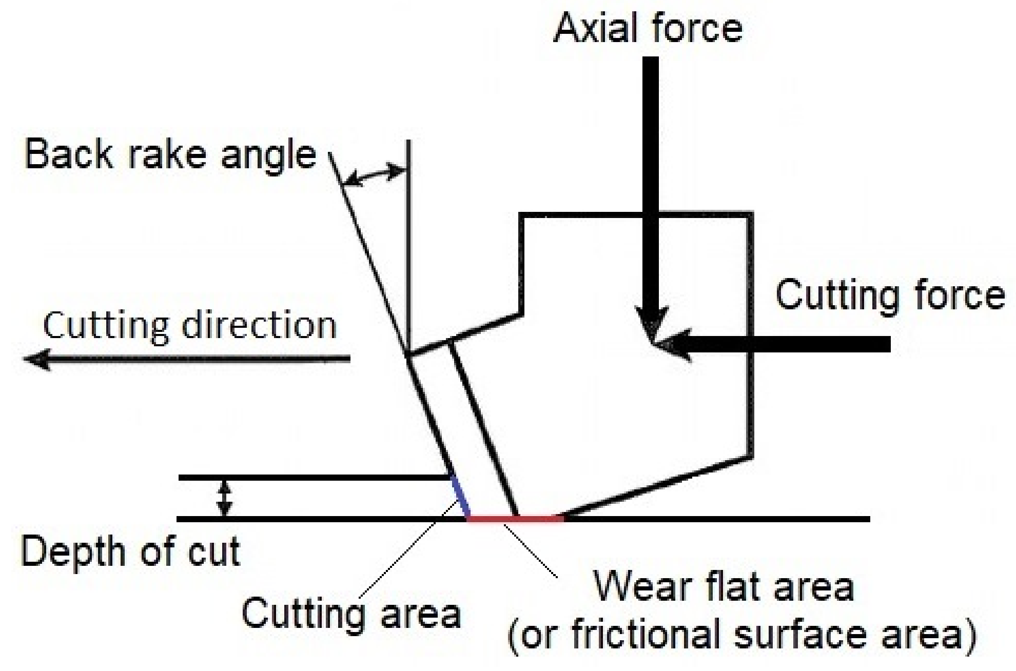
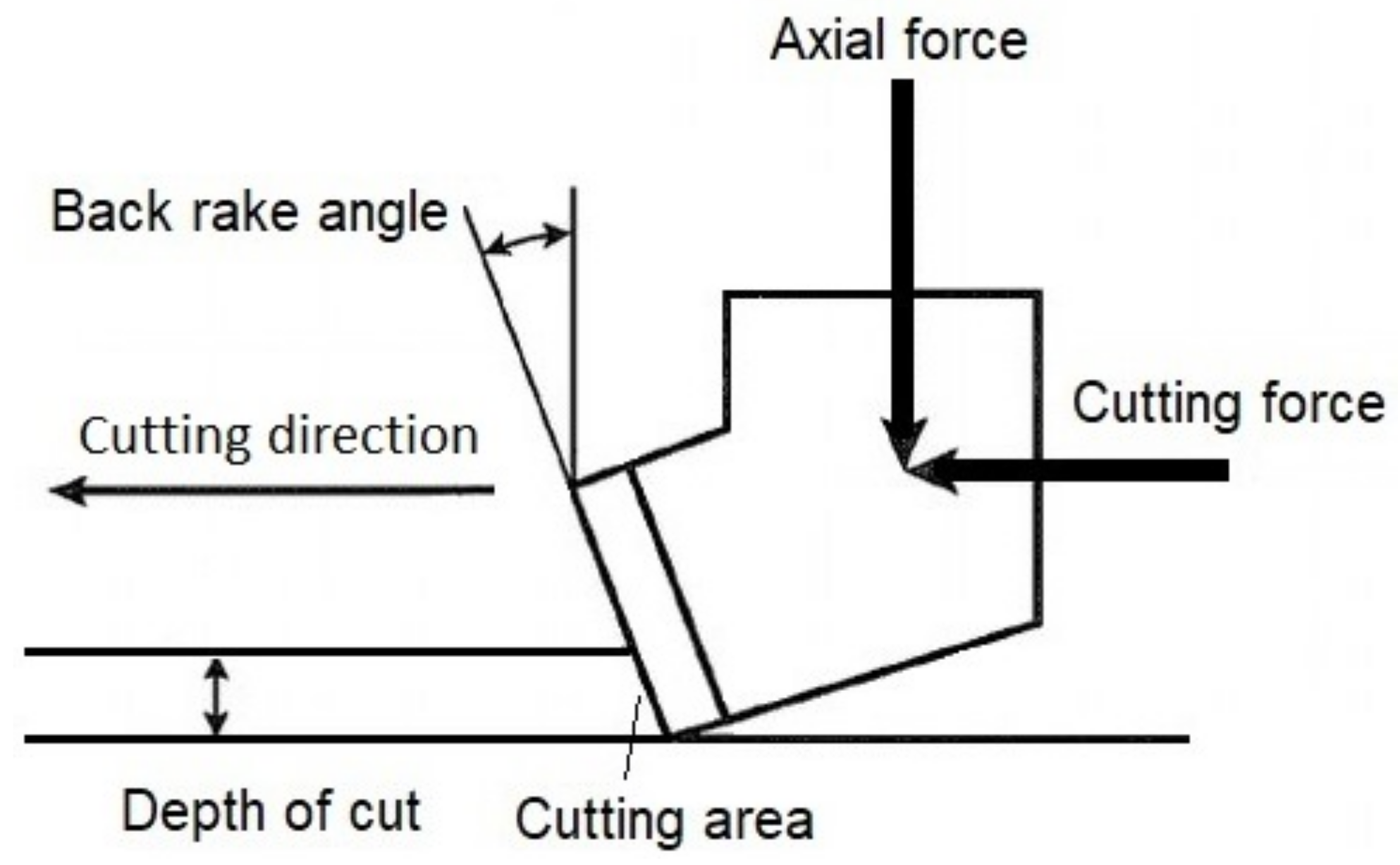
For this study, two sets of separate experimental data were collected from the literature to regress correlations for normal and cutting force. Experimental data covered force values for both new and dull circular cutters. Data collected and applied in the regression include cutter diameter, cutting area, cutter wear flat (or frictional surface) area, back-rake angle, cutter wear height, rock drillability, and differential pressure (see Figure 1 and Figure 2). Besides utilizing geometrical analysis, the cutting area was calculated from the depth of cut that was measured during the experiments in the literature. For those works that did not report a value of rock drillability, an estimate of drillability was calculated from equations in the publication by Liang et al. [15] based on the data provided for rock cutting utilizing new cutter tests. For new cutters, the frictional surface area below the cutter is considered zero and for dull cutters, values reported in the literature are applied in the calculations; however, the number of studies examining cutter–rock interaction exceeds those cited here. Some necessary parameters were not reported in a few studies and the data package was not clear enough to be implemented.
A summary of experimental data points from numerous studies is presented in Table 2. In total, 779 and 654 data points were collected for cutting and normal force, respectively. The back-rake angle in the experiments ranges from 0 to 40 degrees, the fluid confining pressure was between 0 to 450 psi, cutter sizes from 12.7 mm to 19 mm were utilized and various rock types with different mechanical and petrophysical properties were implemented for testing. Table 3 and Table 4 represent the statistical values of data for normal and cutting forces.
2.2. Methodology and Calculations
2.2.1. Regression Analysis
Experimental studies with different cutter sizes on numerous rock types and under varied experimental conditions have revealed that cutting and normal forces are related to the back-rake angle, cutting and wear flat area, rock drillability, differential pressure, and cutter worn height through some simple linear and nonlinear equations. As a result, such relationship in the governing equations for the cutting force and normal force should persist and show up in the correlations. Table 5 summarizes the mathematical formulation of the basis regression functions based on the rock–cutter interface parameters. Each basis function suggests a transformation for each of the objective parameters. The basis functions for back-rake angle, wear flat area, differential pressure, and wear height are proposed in such a way that if the objective parameter is zero then the parameters do not influence the force values. Moreover, if the cutting area is zero then forces become zero as well. Therefore, correlations are valid if drilling continues for the applied parameters. The coefficient in these basis functions is limited to some values based on the experimental outcomes and such bounds are tabulated in Table 5.
Using the experimental data used in this study, the basis functions are correlated. Almost all published research studies in this field attempt to study the impact of a single parameter on cutting and normal forces by holding all other parameters constant and performing experiments with a single parameter. These findings of studies unequivocally depicted the type of function relating objective parameter to measured force values. Accordingly, Rafatian et al. [8] studied the effects of differential pressure on cutting and normal force while retaining other parameters and proposed an exponential relationship between forces and confining pressure. The relationship between forces and single parameter analysis in the literature has been utilized to establish a basis function for each of these basis functions. Moreover, a short analysis of the procedure for determining the basis functions is presented in [46].
Table 5.
Proposed basis regression functions based on experimental observations for and .
| Parameter | Basis Function | Multiplier Bounds | Related References |
|---|---|---|---|
| Back-Rake Angle | [7,15,16,47] | ||
| Cutting Area | [2,3,7,11,15,16,45,46] | ||
| Wear Flat Area | [2,3,48] | ||
| Rock Drillability | [16] | ||
| Differential Pressure | [1,7,8,11,12,46] | ||
| Cutter Wear Height | [2,3,48] |
As it is demonstrated in Table 5, each of the functions entails one or two multipliers which are bounded to some values based on the observations for every single parameter reported in the literature. The basis function for wear flat area and cutter wear height were configured in such a way that if the cutter status is new then these parameters do not affect the force values.
Two equations were developed by combining basis functions to estimate normal and cutting forces (Equations (1) and (2)). The proportionality of the combination of basis functions is switched to equality by incorporating proportionality constants . In the following correlations, the constants and carry the influence of those parameters such as cutting speed, chamfer, and side-rake angles because there is not enough experimental data to include them in the regression process.
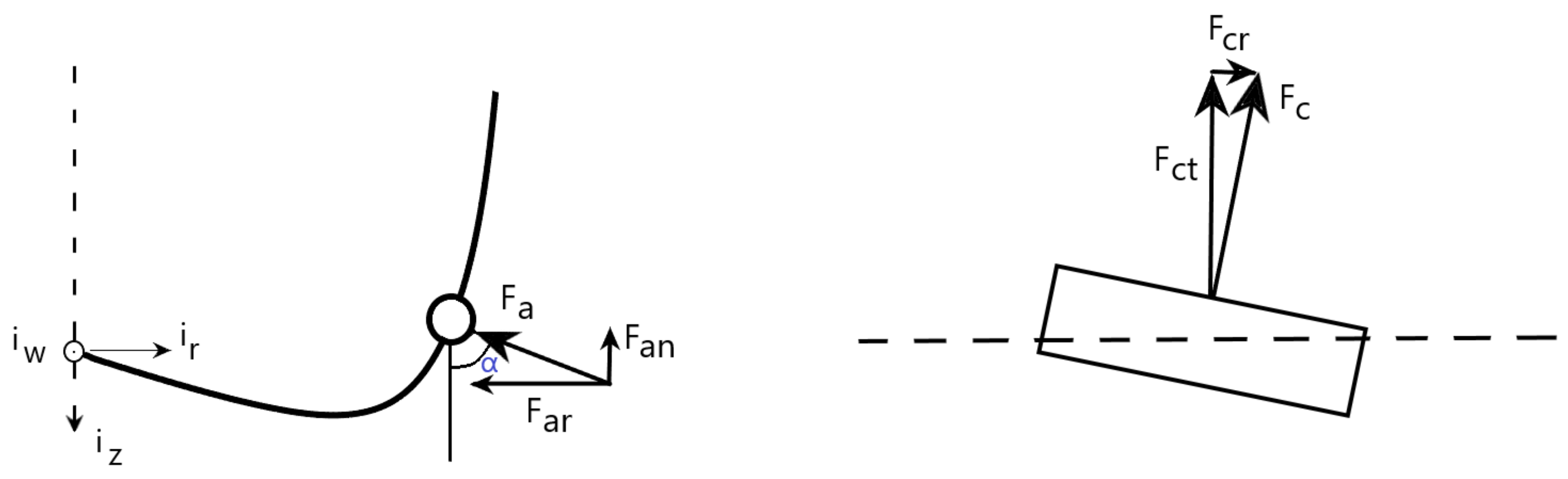
A back-rake angle is represented by in these equations. It is the angle between the cutter face and the vertical axis. The is the area of contact between the cutting face and the rock. It is dependent on the depth of penetration as illustrated in Figure 1 and Figure 2. The wear area below the cutter is demonstrated by . The area beneath the cutter is believed to be zero when the cutter is new, and once the cutter begins to wear, the friction forces applied by this surface contribute to the cutting force. When the increases, the depth of cutting decreases assuming constant cutting and normal forces are applied. As stated previously, K is the rock drillability, which depends on the physical properties of the rock (porosity and permeability), lithology, the module of elasticity and Poisson’s ratio. The is the confining pressure applied during rock cutting. The confining pressure is the difference between the equivalent circulation pressure and the pore pressure in an actual drilling operation. The stands for the height of the cutter that is worn during the cutting process. It may be possible to relate this wear height to the wear area below the cutter, while the chamfer angle should be taken into account when transforming geometrically.
To perform regression, different optimization techniques were used, such as the genetic algorithm, deep learning, particle swarm optimization, and function of MATLAB. The scope of all these techniques was to minimize the objective function defined in Equation (3). It is the sum of the difference between the force measured during experiments, , and the calculated values from correlations, ; however, the difference value for each data point is normalized using the experiment data. Using the techniques, the objective was to minimize the difference between the measured and calculated values, so a minimization algorithm was employed. Constrained optimization was performed based on the upper and lower bounds and the output solution for the objective function is valid for these intervals. Optimization of the objective function resulted in R-squared values (coefficient of determination of the percentage of variation in dependent variables explained by the regression) of and for normal and cutting forces, respectively. Further details about the regression are provided in Table 6 and Table 7. R-square is a measure of the exactness of the regression, but F-factor presents a hypothesis test for the entire regression. This test indicates how strongly the dependent variable is related to the independent parameters. Here the critical F values for the normal and cutting forces based on the degree of freedom are equal to while F values from the regression are and for normal and cutting forces, respectively. The comparison of critical F values with values from the regression indicates that there exists a hypothesis that confirms a relationship between force values and the independent cutter, rock, and operational (confining pressure) parameters.
2.2.2. Regression Techniques
Deep Learning. In addition to regression analysis by numerous techniques such as the genetic algorithm, particle swarm optimization and the function of MATLAB, deep learning techniques were performed on data to correlate normal and cutting forces to cutter design parameters, rock drillability, and differential pressure. Therefore, a neural network model was developed and evaluated using Keras for a regression. The Python software is employed throughout whole process, including data loading, classification, and processing.
The rectifier activation function was used for input and the hidden layers. Three layers with 100, 200, and 100 neurons were assembled to make up the networks. The efficient ADAM optimization algorithm was used, and a mean squared error loss function was instrumented to evaluate the performance of the model. The ADAM algorithm is an optimization technique for training deep learning models that replaces stochastic gradient descent. More details about optimization of nonlinear functions can be found in [49].
As the amount of data points is not high enough to run the usual regression on data points, the plan was to apply all data as input to the network; therefore, the repeated k-fold cross-validation procedure was implemented, and the result is designed to provide a more accurate estimate. The k-fold cross-validation procedure divides a limited dataset into k non-overlapping folds (as usual a good default for k was chosen as 10 folds). Each of the k-folds are given an opportunity to be used as a held back test set, whilst all other folds collectively are used as a training dataset [49].
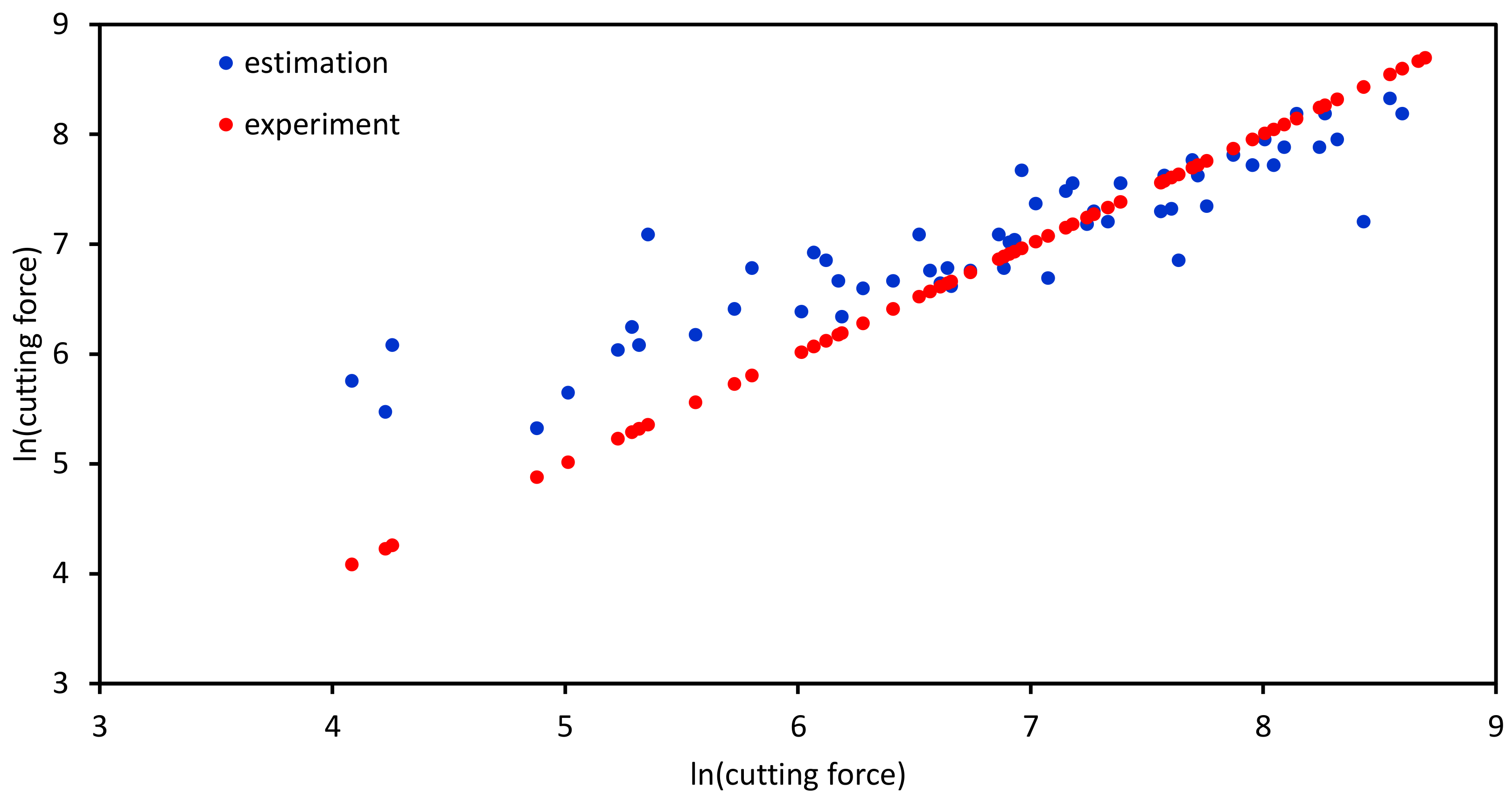
Based on the k-fold cross validation, Figure 3 shows the result for test data by the deep learning network that was trained from the training set of data. The x-axis represents the values from experiments, while the y-axis represents the correlation values. Actually, force values from the experiment are plotted against themselves (red dots) to provide a basis for comparison with correlation values. The blue dots in this plot correspond to the estimated values, which demonstrates an acceptable fit of the data as well as the performance of the deep learning algorithm and network.
Other Optimization Techniques. In mathematics, constrained optimization refers to a set of numerical procedures for optimizing an objective function with respect to a number of variables. This is performed while taking into account constraints on the variables in question. Existing models of constraint optimization include linear, non-linear, multiobjective, and distributed models. Solving such problems is usually accomplished by using linear programming, matrix algebra, branching and bounding algorithms, and Lagrange multipliers.
The genetic algorithm (GA) is an optimization method that replicates the natural selection process that occurs in biological evolution in solving constrained and unconstrained problems. In essence, the algorithm generates a population of solutions, using guided random search, that is continuously modified. Genetic algorithms produce children for the next generation by randomly selecting individuals from the current population as parents. Over successive generations, the population evolves toward an optimal solution. The approach is suitable when dealing with a huge and complex data set.
The Optimization Toolbox in MATLAB is equipped with a function called fmincon, which seeks the minimal value of a mathematical function of multiple variables in a region delimited by linear constraints and bounds. In this study, we rely on the constraints applied by the basis functions mentioned in Table 5 to implement constraints for minimization of the objective function.
3. Drilling Dynamics Modeling
The methodology for modeling the dynamics of drilling includes modeling the drilling bit as an equivalent cutter and an equivalent blade, an approach that links bit models to measurements, and an analysis of the force and specific energy on equivalent cutters. The following is a short description of each of these topics.
3.1. Bit Models
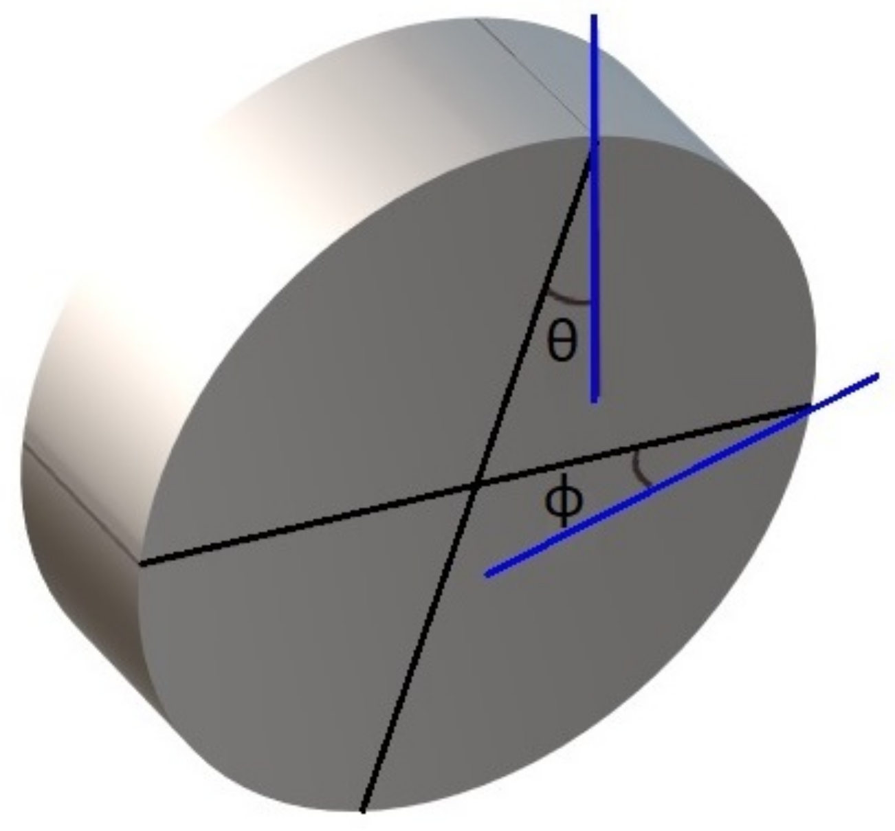
In accordance with the study requirements, drilling bits can be modeled geometrically in two and three dimensions. These approaches differ substantially, including the inclusion of side-rake in the dimensional analysis and the calculation of lateral forces on cutters. The back-rake and side-rake angles on a single cutter are graphically represented in Figure 4. An angle made by the cutter face with a line parallel to the bit axis is known as the back-rake, and an angle made by the cutter face with a radial line perpendicular to the bit axis is known as the side-rake. As described in [20], the other parameters required to define the geometry of cutters on a PDC bit are the circumferential angle, radial position, normal position, and normal angle. There may be specific design parameters depending on the type of cutter, such as the back-rake angle (), the side-rake angle (), the clearance angle (), and the wear flat length (l). When drilling, the back-rake and side-rake angles remain constant, while the clearance angle and the wear flat length are subject to change. In the case of circular cutters, the clearance angles decrease from some predetermined value to zero as the wear of the cutter increases, and the wear length increases from zero (for circular cutters) to some value (more details are provided in [4]).
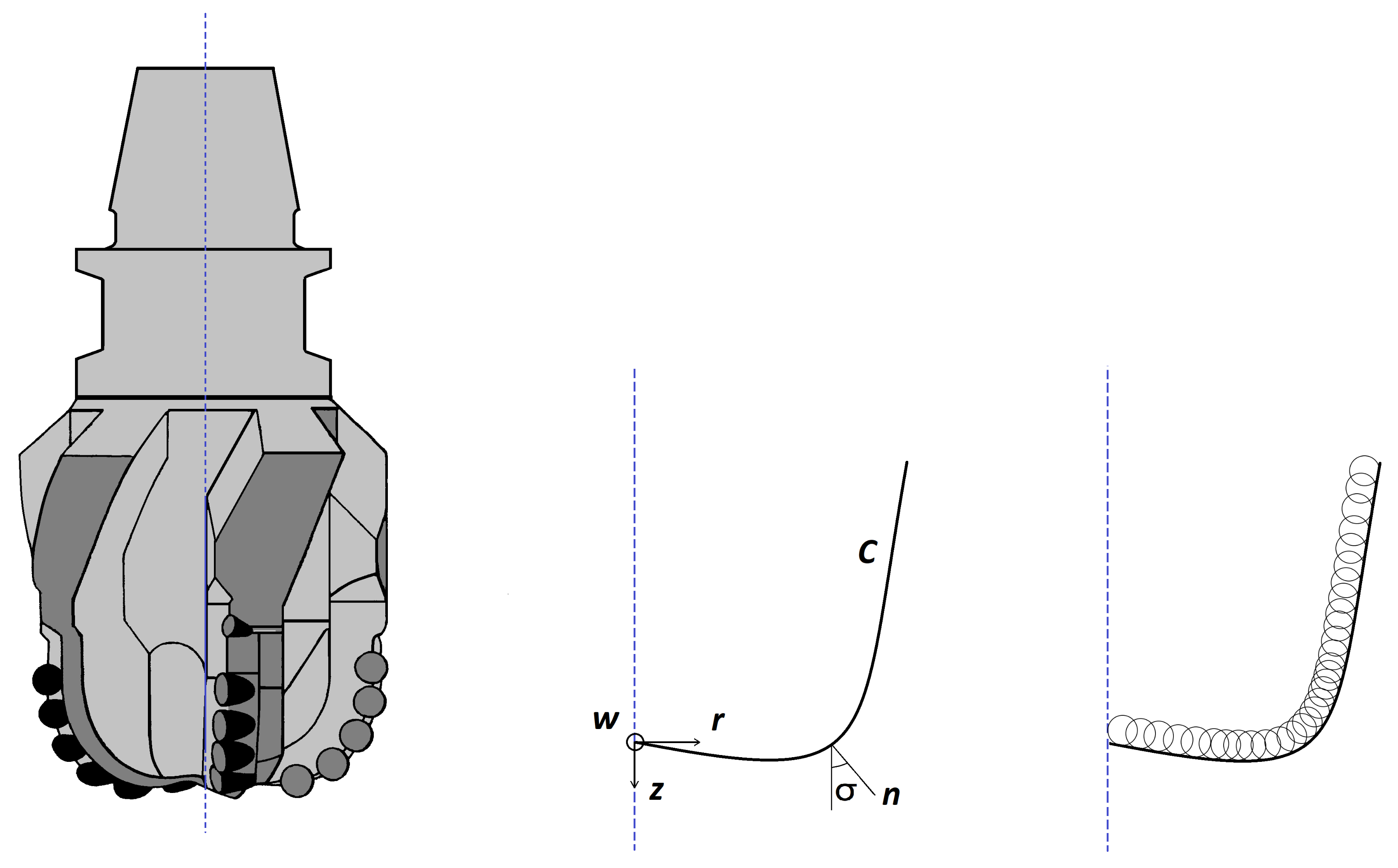
In order to continuously evaluate the dynamics of the PDC bits during drilling, a reference time and depth should be established in order to average drilling parameters and evaluate objective parameters (forces on cutters, torque, and specific energy). Dynamic and kinematic drilling variables can be averaged using the revolution of the bit [25]. In essence, the idea is to calculate the net effect of all cutters on the bit that drills depth d per revolution by averaging them. PDC bits have been the subject of a number of experimental and theoretical studies aimed at simulating their condition and behavior with regard to the cutter state and their role in drilling [2,3,15,20]. Since such models are modeled individually, geometric modeling and implementation are complex as each cutter is responsible for drilling as well as being subjected to both tangential and normal forces. It is possible to construct equivalent blades (imitating the cross section of a bit profile) from cutter traces in order to accommodate the complexity of modeling geometrical features and the inclusion of real-time drilling data, as illustrated in Figure 5. The idea of making an equivalent blade has been proposed by some researchers [3,4,25]. The equivalent blade is constructed by taking the trace of all cutters in one revolution on a vertical plane containing the bit axis (Figure 6).
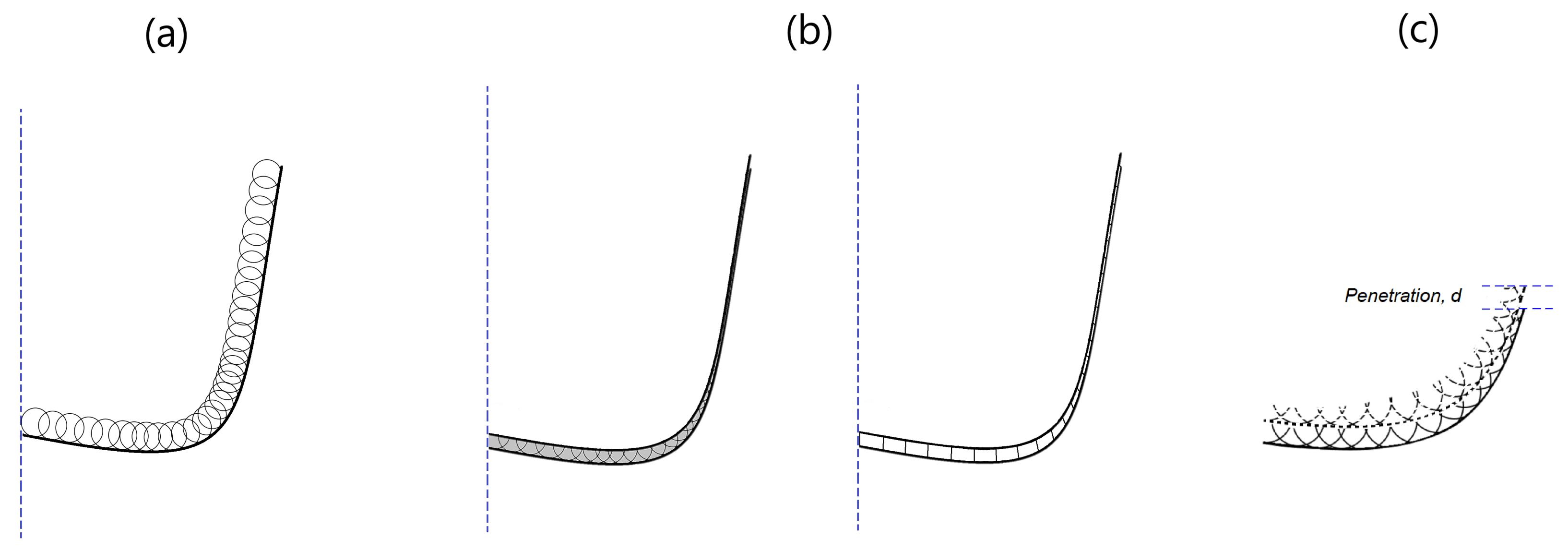
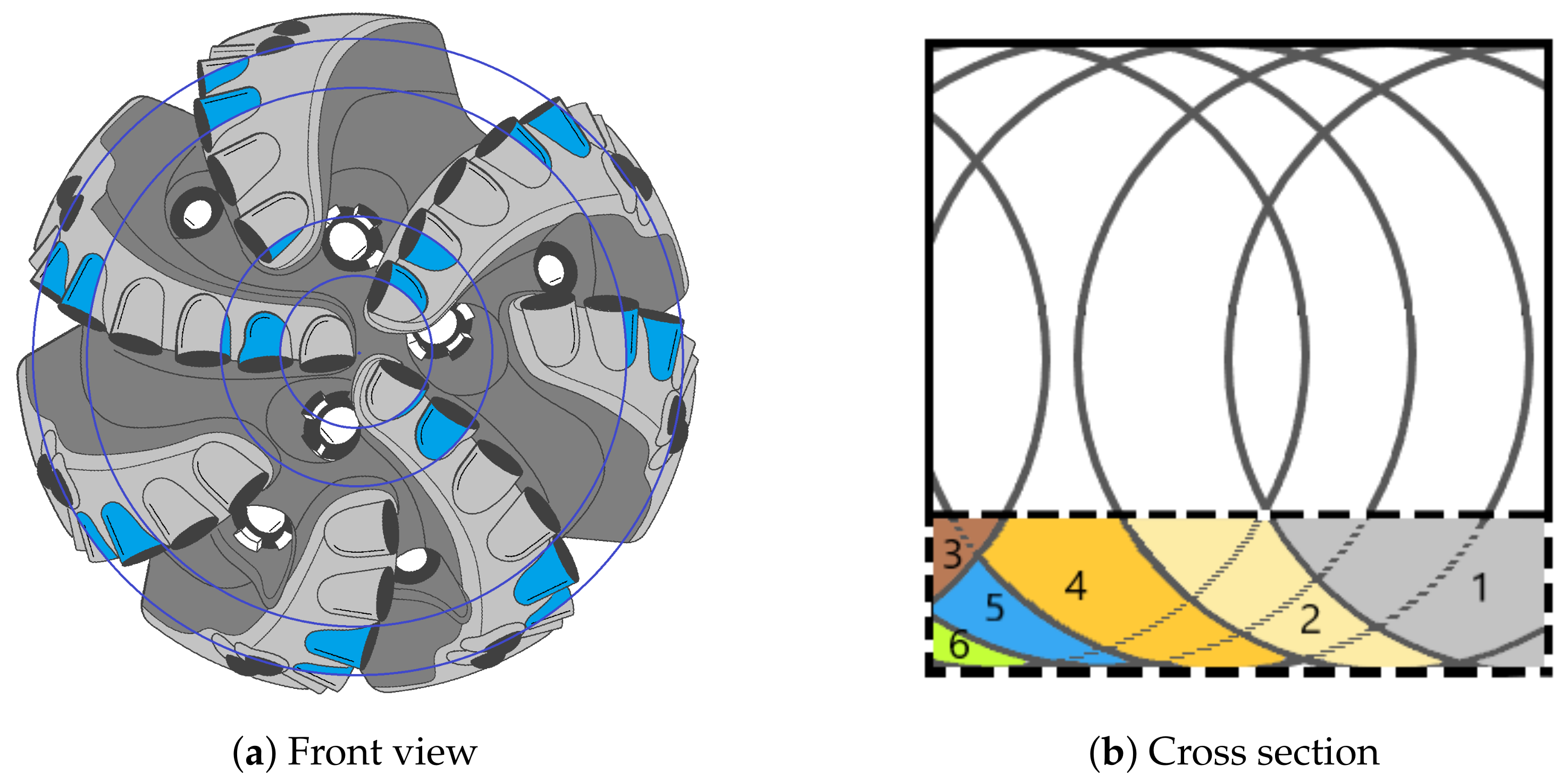
The equivalent blade could also be defined using a cylindrical coordinate system (r, z, w) (Figure 5). In this figure, n represents the normal direction to the bit profile and indicates the angle between the normal to the bit profile and the bit axis. The equivalent blade allows for the definition of all design and geometrical parameters of the cutter on the basis of continuous or discontinuous step-wise functions. The equivalent blade consists of several components known as equivalent cutters. Figure 7 illustrates how equivalent blades are created through contributions from several cutters (Figure 7a); therefore, in an equivalent cutter, all cutters are responsible for removing a certain amount of rock in a predetermined sequence (Figure 7b). Since cutters overlap each other, if one part of a cutter wears or chips, the next cutter will compensate for the damage. During this period, some cutters may experience a change in force, but the total weight of the bit and the torque applied to it will remain the same, while the penetration rate should remain the same. It continues in this manner until all cutters wear out, and cannot compensate for damage to other cutters, and the equivalent cutter becomes less efficient. In the model developed here, we assume that all cutters located at almost equal radial distance have the same geometrical and design characteristics. In this way, the equivalent blade can be discretized into rectangular cutters with known and constant geometric, kinematic, and dynamical parameters along the curve C. Consequently, the interactions between adjacent cutters can be considered as one equivalent cutter.
As shown in Figure 5, the forces transferred by the bit to the cutters can be divided into two components along each axis. In the radial direction, the component responsible for vibration (bit whirl) is called the lateral force. Specifically, we study the weight on the bit and the torque on the bit components along the z-axis and in tangential directions.
3.2. Specific Energy Analysis
In 1963 that Simon [50] and Teale [42] studied the interaction between cutters and rock. There have been numerous experimental and theoretical studies that have examined the interaction between cutter and rock based on the concept of specific energy [4,6,11,16,19,51]. In this paper, forces at the cutter–rock interface are investigated using the same approach. It is possible to decompose the force F that is applied to the surface of the cutter, for cutting rock, into two components: (as cutting force) and (as normal or normal force). According to Detournay and Defournay [4], the following relationship could be written for the components of cutting and normal force:
Rectangular cutters have an area of A equal to the product of the width, , multiplied by the depth of penetration, d, per rotation. A parameter called describes the intrinsic specific energy which varies with the type of rock, the cutter position on the blade, and the confining pressure. Parameter represents the ratio of vertical to horizontal forces acting on the cutting surface. Figure 1 and Figure 2 shows a flat wear area beneath blunt cutters. Taking this into account, it is possible to represent the forces on cutters in terms of horizontal and vertical components as follows [4]:
Then, the general equation of specific energy for a cutter could be written as:
where, in the above relationship, is the coefficient of friction at the wear flat–rock interface, and drilling strength and total specific energy could be defined as,
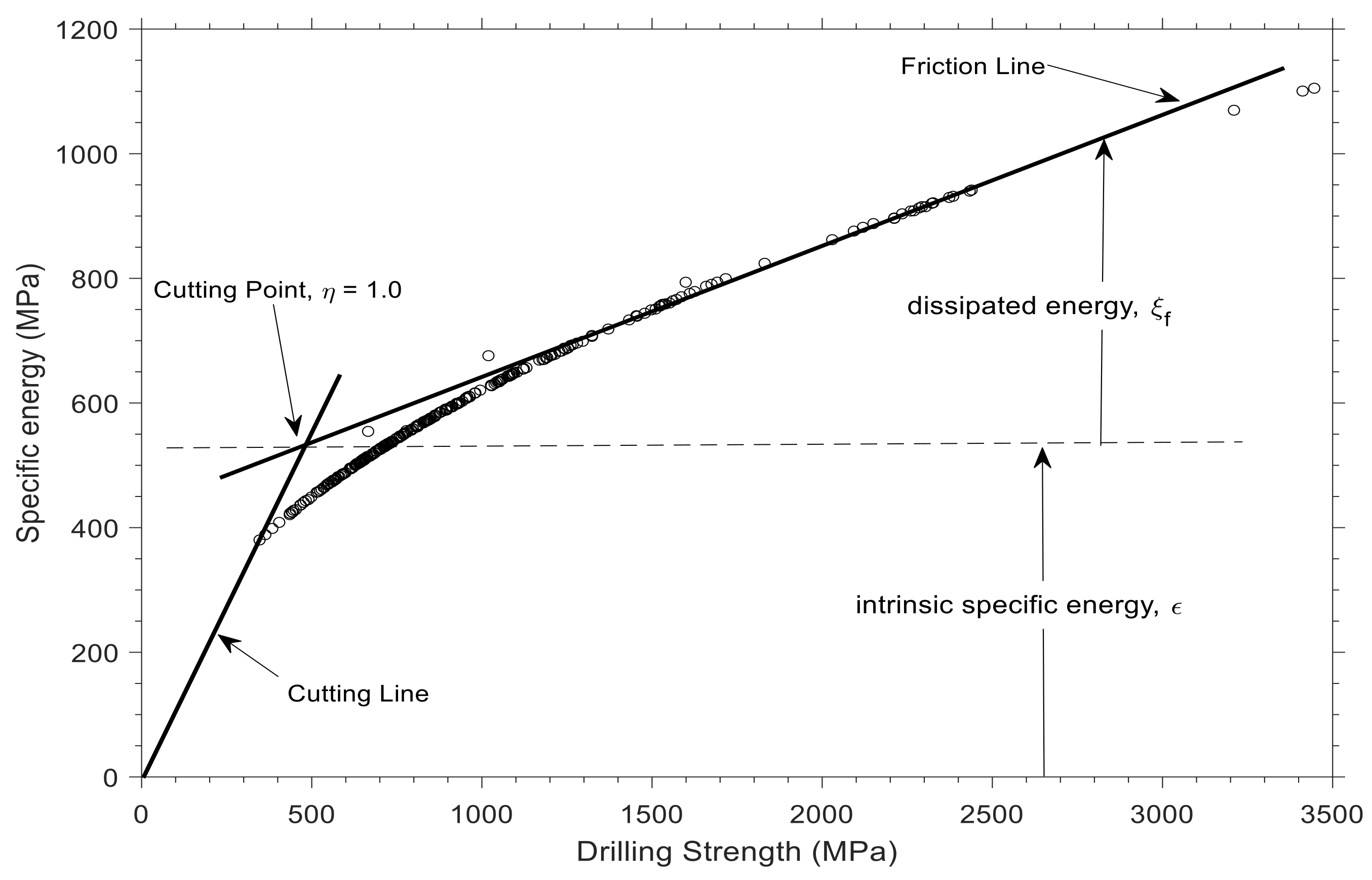
Experimental analysis of a new and blunt PDC cutter demonstrates a linear relationship between the actual specific energy and the intrinsic specific energy [4,6,11]. Generally, the actual specific energy consists of dissipated energy through the wear flats and energy used to cut rock. One can construct a measure of bit dullness by defining drilling efficiency, , as the ratio of . A value of 1 indicates a sharp cutter, whereas a value of 0 indicates a perfectly dull cutter. Figure 8 illustrates the relationship between specific energy and drilling strength for a set of data utilized in this study, i.e., E-S plot. It shows the cutting point as the energy and stress state of a perfectly sharp cutter. More details on such plots is represented graphically by Detournay and Defournay [4]. Wearing out the cutter causes a fraction of the energy delivered to the bit to be lost in the wear flat surface; therefore, more energy should be applied to maintain penetration. This will result in cutter state points departing from the cutting point and moving along the friction line.
According to Detournay et al. [4,6], the penetration rate affects the torque value (Equation (11)). In this equation, torque is related to the weight on the bit and penetration by assuming two processes that occur during drilling, cutting, and friction. The state of a sharp cutter is represented in Figure 8 by , but the condition of a fully worn cutter could theoretically be expressed by . In comparison to the effort consumed at the drill bit, torque on the bit has two components: frictional and cutting.
In this equation, a is the bit radius, and represents the frictional component of the weight on the bit and torque, as well as the effect of the bit design parameters on the bit–rock interaction.
3.3. Data Analytic Approach
To qualitatively monitor drilling bit dynamics, we have continuously monitored specific energy and drilling strength on the equivalent cutters. Based on depth intervals, a single plot could be generated for each of the equivalent cutters, and the trend of the cutting points on the friction line could be monitored. A dynamic analysis of cutters is performed in this study every 30 s by implementing along-string measurements acquired during the drilling process. Preceding the discussion of the model design approach, the following considerations are discussed:
- Since all cutters that are located at the same radial distance (from the axis of the bit) have the same design characteristics, their traces can be summed up into a single cutter equivalent.
- The cleaning action of the hydraulic system is efficient enough to remove all cuttings ahead of cutters and cuttings do not adversely affecting drilling performance.
- Assuming homogeneity of the rock all over the bottom of the hole; therefore, the drillability value would be constant and would apply to all equivalent cutters.
A new bit can be assumed to have zero wear height and zero wear flat area with acceptable accuracy. It is possible to apply the procedure to determine and continuously monitor the drillability constant of the rock when downhole measurements are available close to the bit. Moreover, if the lithology changes during drilling, its value can be calculated since the bit status could be known from the previous interval. Nevertheless, when measurements of weight and torque are available from downhole measurements, the bit status and rock drillability can be estimated simultaneously. In this study, surface measurements are used to analyze the drill dynamics of the string and bit.
The forces acting on a cutter can be calculated by considering cutter parameters, rock properties, penetration rate, and summing these forces to determine the torque on the bit and the weight on the bit. Considering the force distribution on individual equivalent cutters (Figure 9), the torque on the bit and the weight on the bit can be expressed as follows:
In this equation, represents the radial distance from the center of the bit to the center of the objective cutter; N is the number of equivalent cutters.
Having measurements of the weight on the bit from surface sensors and assuming a linear function for the torque and the weight on bit, recursive least square estimation (RLS) could be applied to estimate cutter wear status from a series of continuous data. Then, the torque on the bit is estimated and a plot of specific energy versus drilling strength for each equivalent cutter provides a qualitative estimate of drilling dynamics at the bit.
All parameters mentioned in Equation (1) except wear height and wear flat area could be assumed to be known; therefore, the equation for normal force could be reduced to,
where and x are defined as follows,
Therefore, the equation of weight on the bit in Equation (13) becomes,
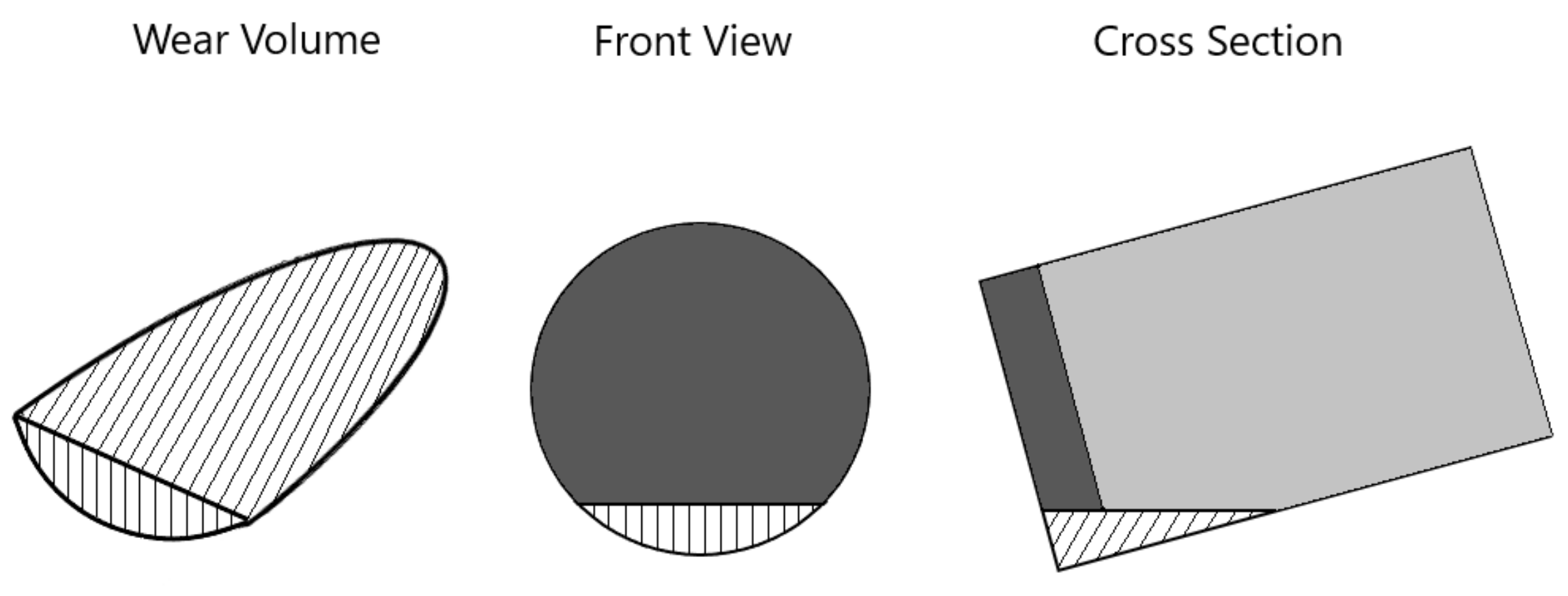
As an assumption in this study, the clearance angle is considered to be zero, so the wear height and the wear flat area can be geometrically related through the following geometry-based equation. Figure 10 shows a schematic diagram of the worn section and wear flat area.
For a circular cutter,
For a equivalent rectangular cutter,
While continuous data are recorded during drilling, an estimation of the bit status and specific energy and the torque at the bit and drill string can be made. Briefly, the process includes:
- Geometrical modeling of the PDC bit as equivalent cutter and blade.
- Recording of drilling parameters mainly the torque and the weight on the bit, rate of penetration (ROP) using along-string measurement system.
- Updating cutter status and calculate normal and cutting forces, specific energy and the torque at the cutters.
- Estimate torque at the bit and comparing it to the torque delivered to the drill string at the surface to monitor drill string dynamics for possible drilling problems.
Recursive least squares estimation could be used to estimate equivalent cutter wear status on the basis of noisy measurements of the weight on the bit. The measurement noise is defined through parameters v. Writing Equation (18) for k noisy measurement of weight on bit as,
This set of equations can be assembled into matrix form as,
for simplicity, the weight on the bit, WOB, is written as y. Now one can define the measurement residual as the difference between the noisy measurements and vector by:
Using the Gauss theorem, the most probable value of the vector x is vector that minimizes the sum of squares between the recorded values y and the vector . So, could be computed in such way that minimizes the objective function J, where J is defined as,
therefore, final values for will become as follows provided that and H is full rank. This means that the number of measurements k is greater than the number of equivalent cutters N that we are trying to estimate the wear height of the cutters. Solving for ,
Note that H matrix in Equation (25) is a matrix. On the other hand with drilling measurement data recorded sequentially one has to update the estimate of x with each new measurement. If the number of measurements become large, then calculating a large augmented form of matrix H is cumbersome. The solution to this complexity is to implement recursive computation of objective parameter x [52]. Suppose is known after measurements, then for the new measurement a linear recursive estimator can be written in the form
In the above equation and the quantity are called the estimator gain matrix and the correction term, respectively. The estimator gain matrix can be calculated by,
In the above equation is the estimation-error co-variance as follows and stands for the co-variance of measurement noise .
4. Results and Discussion
4.1. Mathematical Modeling
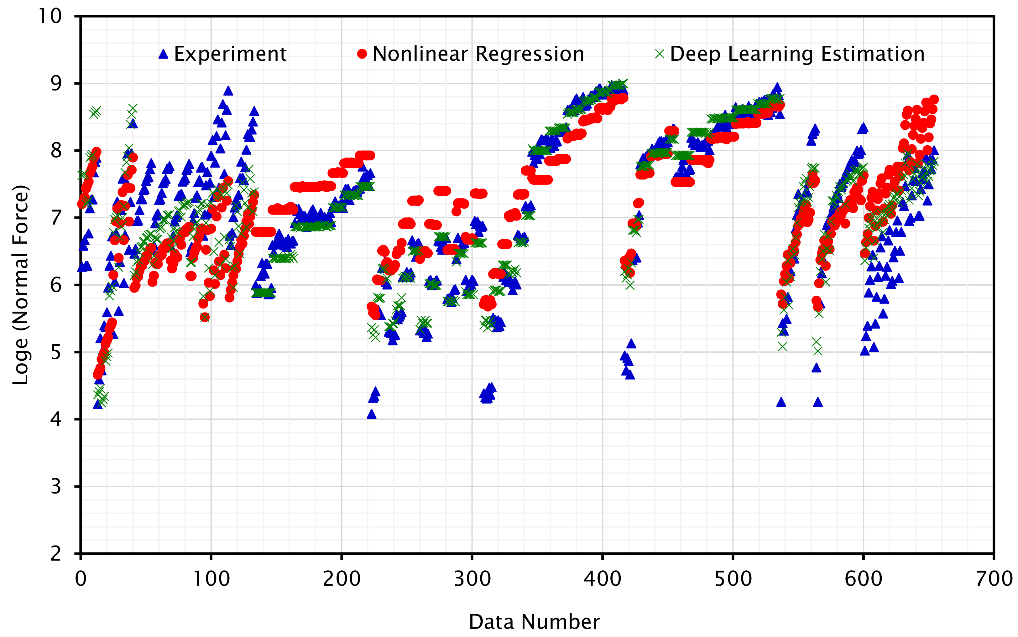
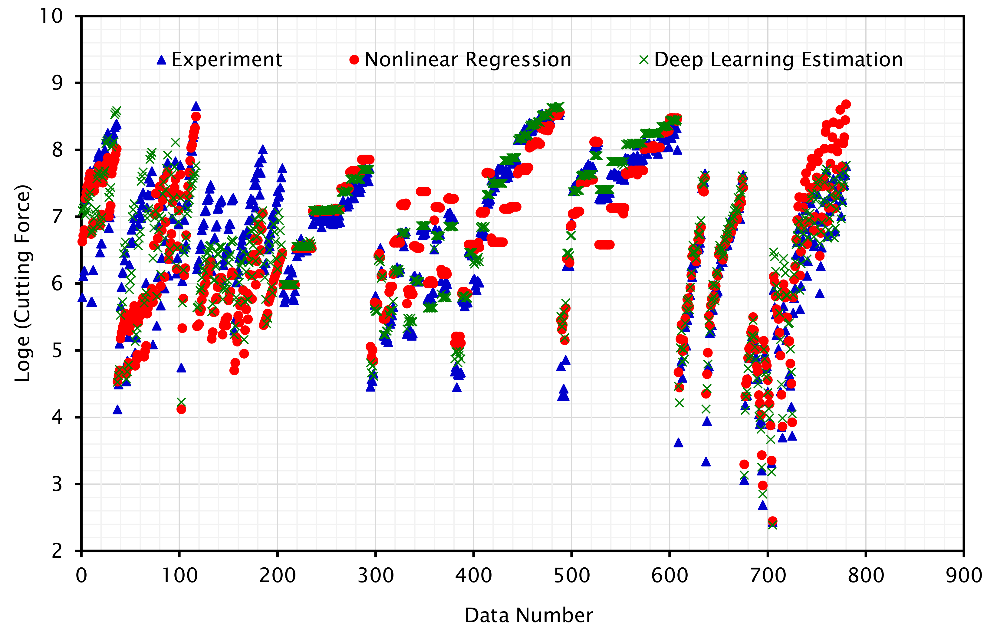
In the first section, we present the results of the regression analysis conducted on the experimental data to develop two equations for the normal and cutting forces at the cutter–rock interface. Table 8 and Table 9 present the result of the regression analysis based on the minimization of the objective function. In addition, the tables provide numerical values for the coefficients appearing in nonlinear correlations (Equations (1) and (2)) based on the nonlinear correlations. In this equation, the normal force and the cutting force are determined by the coefficients and , respectively. It should be noted that and are proportionality constants that include parameters that have not been explicitly introduced into the correlations. As examples of these parameters, the cutting speed, chamfer, and side-rake angle were not included in the regression analysis due to the lack of experimental data in the literature. Aside from this, the coefficients and represent regression coefficients for back-rake angle, cutting area, wear flat area, rock drillability, differential pressure, and cutter wear height, respectively. The in these two plots indicates the natural logarithm of the force values.
Figure 11 and Figure 12 illustrate the force values from the experimental data as well as values calculated based on regressed models and deep learning estimation. Regression and experimental data points show a good correlation. Some data points are inconclusive because none of the experiments reported in the literature considered all the design and operational parameters (parameters introduced in this study for regression). Furthermore, the values estimated by nonlinear regression and deep learning follow a similar pattern and are nearly identical.
An analysis of variance (ANOVA) can be implemented along with regression techniques to determine the relative significance of each parameter. Analysis of variance (ANOVA) is a method used in statistics to study the observed aggregate variability within a set of data based on two categories of factors: systematic and random. Data sets are statistically impacted by systematic factors, while random factors are not. It is beyond the scope of this study to discuss the ANOVA and these details can be found in statistics references.
An ANOVA incorporates a hypothesis test (t-test) to determine the contribution of each parameter to predicting the value of the dependent variable. MATLAB and STATA software were used to perform the ANOVA analysis for the normal and tangential forces; the results can be found in Table 8 and Table 9. T-stat values indicate that the cutting area, rock drillability, and differential pressure have the greatest influence (more than 70%) on normal and cutting forces. Further, the p-values for each variable are less than 0.05, which confirms the hypothesis of a correlation existing between the variables.
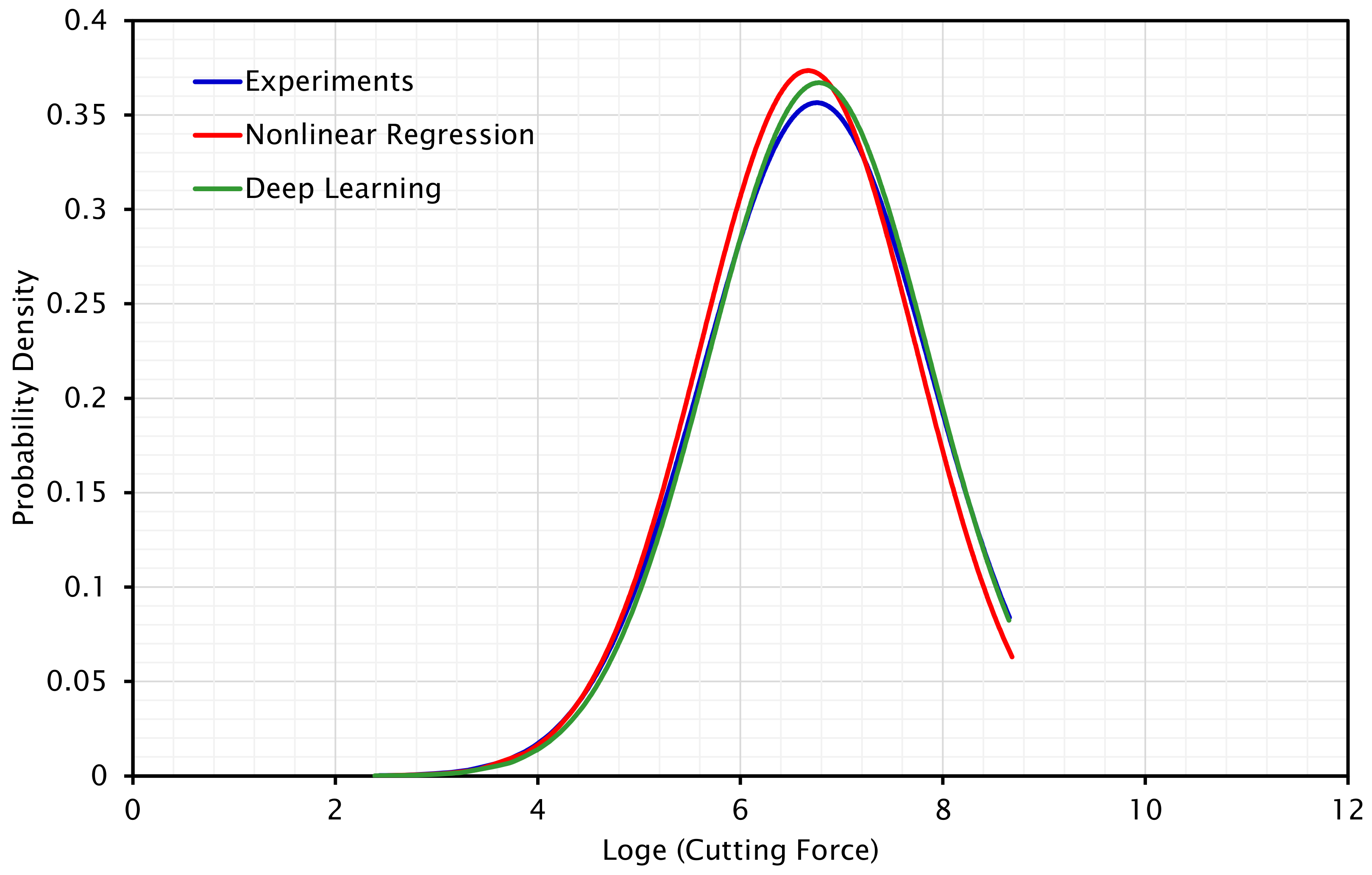
In addition to the ANOVA result, which validates the regression findings, the standard deviation (SD) of the three data series (experimental results, nonlinear regression outcomes, and deep learning regression results) is found to be 1.1187, 1.0678, and 1.0865 for cutting force and 1.0990, 0.8261, and 1.0170 for normal force. The standard deviation values of the regression outcomes of cutting force are almost equal to the SD value of the experimental data; however, the standard deviation number of nonlinear regression results differs somewhat from the experimental and deep learning regression findings for normal force. In general, the outcomes confirm the values of the regression process. Figure 13 and Figure 14 demonstrate the normal distribution of all data based on the calculated SD values. As predicted, the normal distribution curves of the regressed results (by different approaches) for normal force are narrow and similar to the curve for cutting force. This plot indicates that experimental data and deep learning regressed values have good correlation. The standard deviation of the results by nonlinear regression method is smaller than that of experimental data and deep learning; consequently, the normal distribution for these data is more focused around the mean.
4.2. Drill Bit and String Dynamics
The first part of this study presents two correlations that can be used to calculate the cutting force and the normal force for rock cutting. It is necessary to upscale the forces determined at the cutter level, on a microscale, to link them to measurements at the bit level. It is possible to integrate cutting and normal forces with the torque and weight on the bit by using two different upscaling methods. Firstly, each cutter is considered as an independent element, and the cutter is refined by taking into account the lapping effects of neighboring and following cutters. An example of this approach can be found in [24,53]. Secondly, the entire bit may be regarded as an equivalent blade by combining the cutting areas of the cutters into equivalent cutters and then into an equivalent blade. As a result of this methodology, all cutters generate a single blade, and the bit can be modeled by analyzing forces on the equivalent cutter and the equivalent blade.
In the algorithm, two sets of drilling data for two bit runs from a well drilled on the Norwegian continental shelf were used to monitor the drilling bit and drill string dynamics. Due to the confidentiality of the data, general titles are used for figures and sketches. Over a distance of approximately 700 m, two PDC bits were used to drill the interval section. An ASM sensor was installed behind the bit for 60 m and it recorded fluid pressure, temperature, and drill string acceleration data. This sensor did not measure the weight or torque on the bit; another ASM sensor was used at the surface to measure the weight and torque on the bit, and these data were used in the analysis. Data measurements are made every two seconds. On the wired drill string, three ASM sensors at three different locations were used to measure the internal and annulus fluid pressure; however, the annulus pressure recorded by the ASM closest to the bit was used to estimate the effective differential pressure ahead of the bit by utilizing the Bingham plastic rheology model. While the bit status is monitored through the calculation of normal force, the torque at the bit is determined based on the equation of cutting force and the results are compared with the measured torque delivered to the drill string.
In this study, two PDC bits were utilized, each with a cutter measuring 16 mm. The equivalent blades for both bits were discretized into equivalent cutters measuring 12 mm and 8 mm, respectively. All cutters in these two bits are assumed to have a back-rake angle of . The results can be referred to the equivalent cutters by noting that the equivalent cutter number 1 corresponds to the innermost cutter, and the equivalent cutter number 12 corresponds to the outermost cutter. In the first few meters following the start of drilling, the cutters are new and the algorithm can be run to determine rock drillability. A drillability value of 4.55 was calculated for bit run number one based on the weight on the bit measurement. It was estimated that the average drillability value of the second interval was equal to 6.
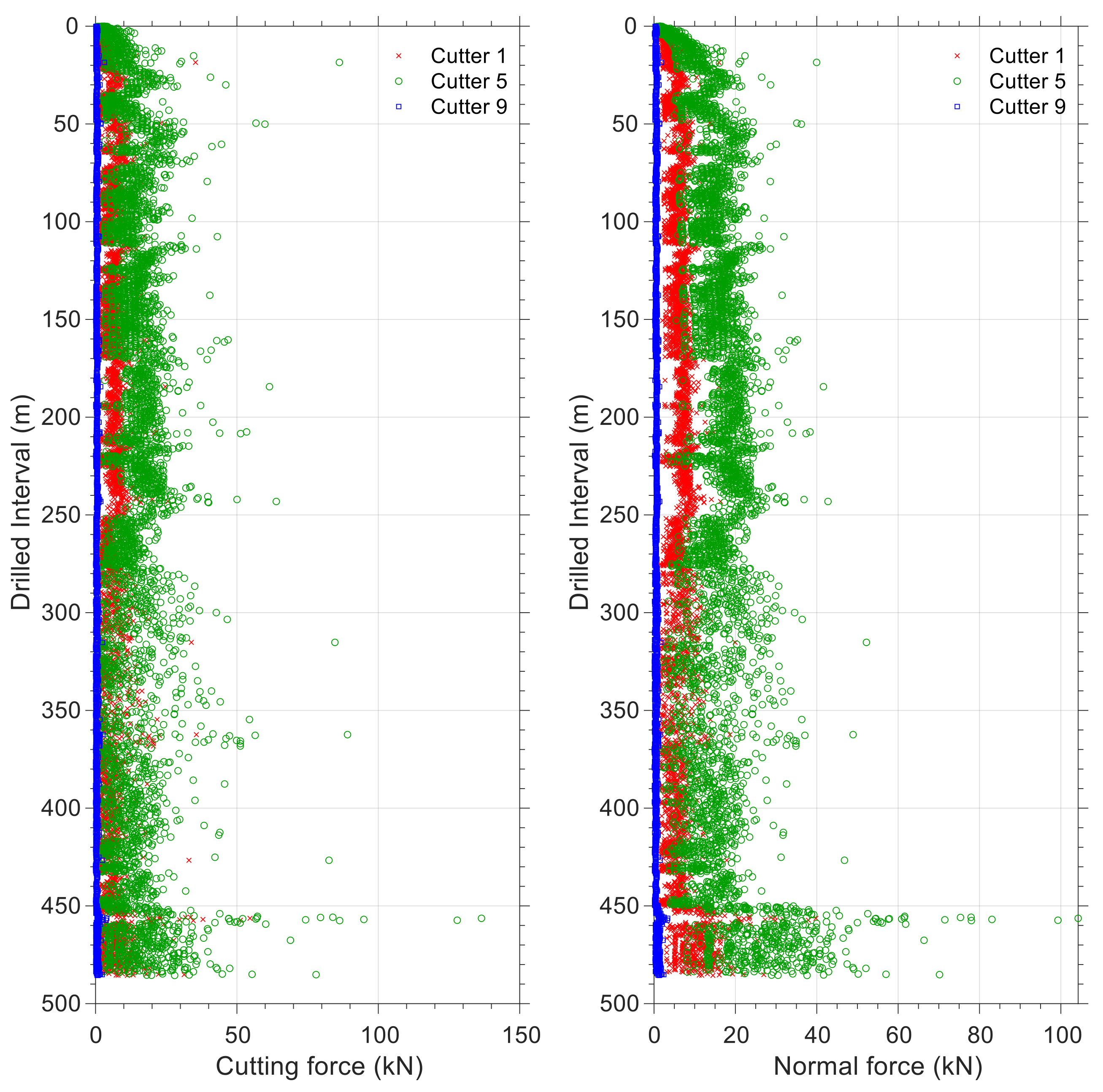
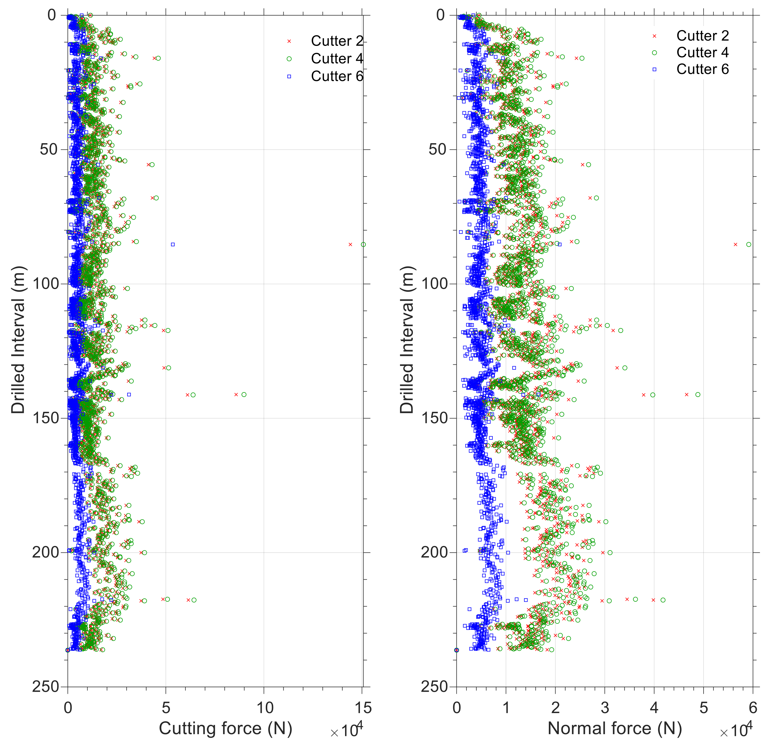
This section also presents the results of the algorithm for two bit runs. As a first step, force analysis is performed on a few sample cutters and is plotted against drilled intervals. A plot of the force on cutters 1, 5, and 9 is shown for bit run number 1 (see Figure 15) and for cutters 2, 4, and 6 for bit run number 2 (see Figure 16) to illustrate how the position of the various equivalent cutters affects the cutting and normal forces. It is because of the bit profile or the curve “C” in Figure 5 that determines how force is distributed along the equivalent blade. In these plots, y-axis represents the drilled interval, with 0 indicating the start of drilling, and the x-axis represents the forces on the equivalent cutters. Compared with the other cutters, equivalent cutter number 5 in bit run number 1 (and equivalent cutter numbers 4 and 6 in Figure 16) is the centermost equivalent cutter. The nose cutters in the bit profile are responsible for carrying the majority of the normal and cutting forces. Equivalent cutters on the gauge area of bits (last equivalent cutters on the equivalent blade) experience the lowest normal force and torque during drilling. It is relevant to note that this condition applies to drilling operations, whereas in reaming operations in a tight borehole, gauge cutters are subjected to the greatest amount of cutting force. Comparing plots for normal and cutting forces (Figure 15 and Figure 16) indicates that they are correlated. In other words, an increase in normal force corresponds to a higher torque value when drilling rock.
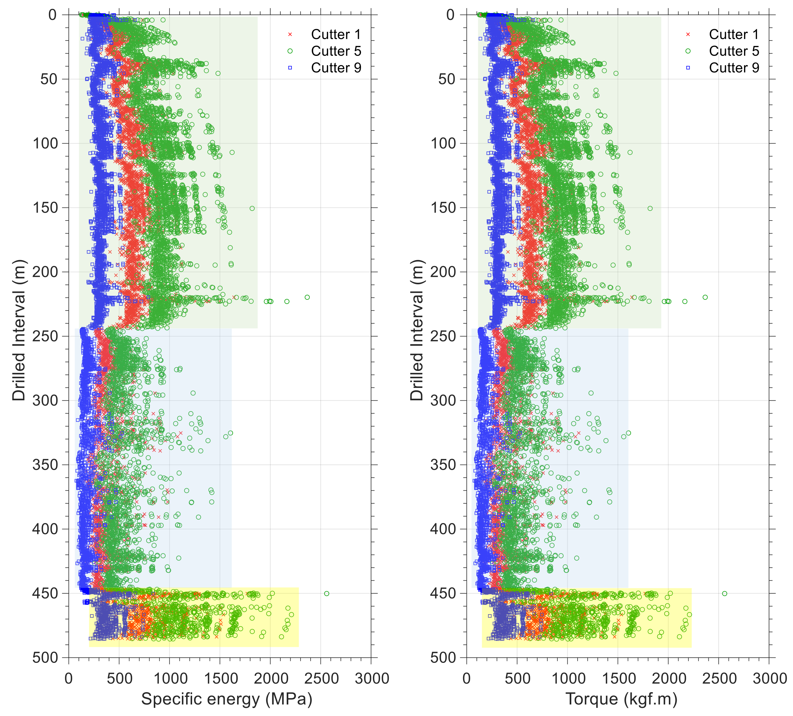
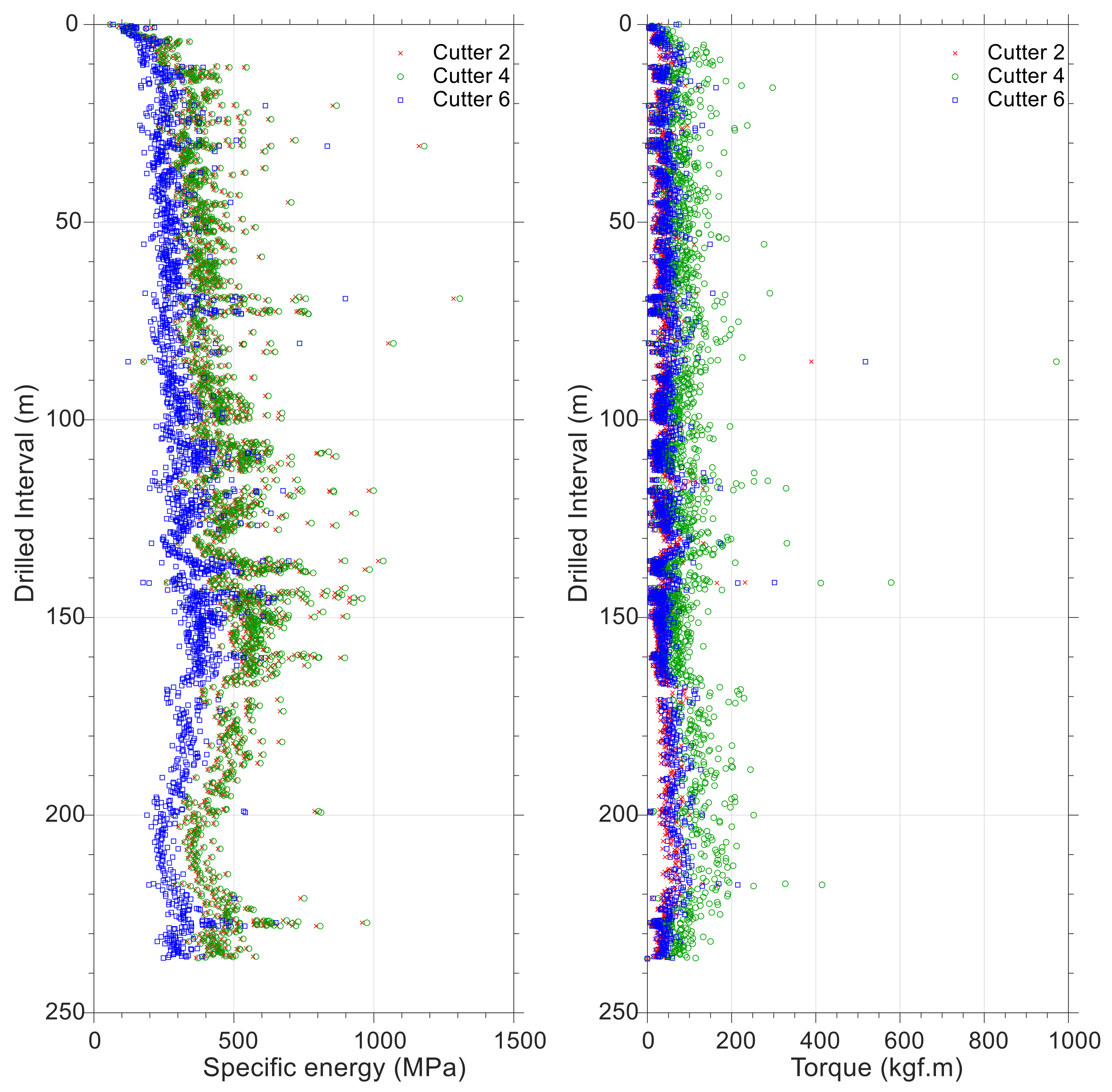
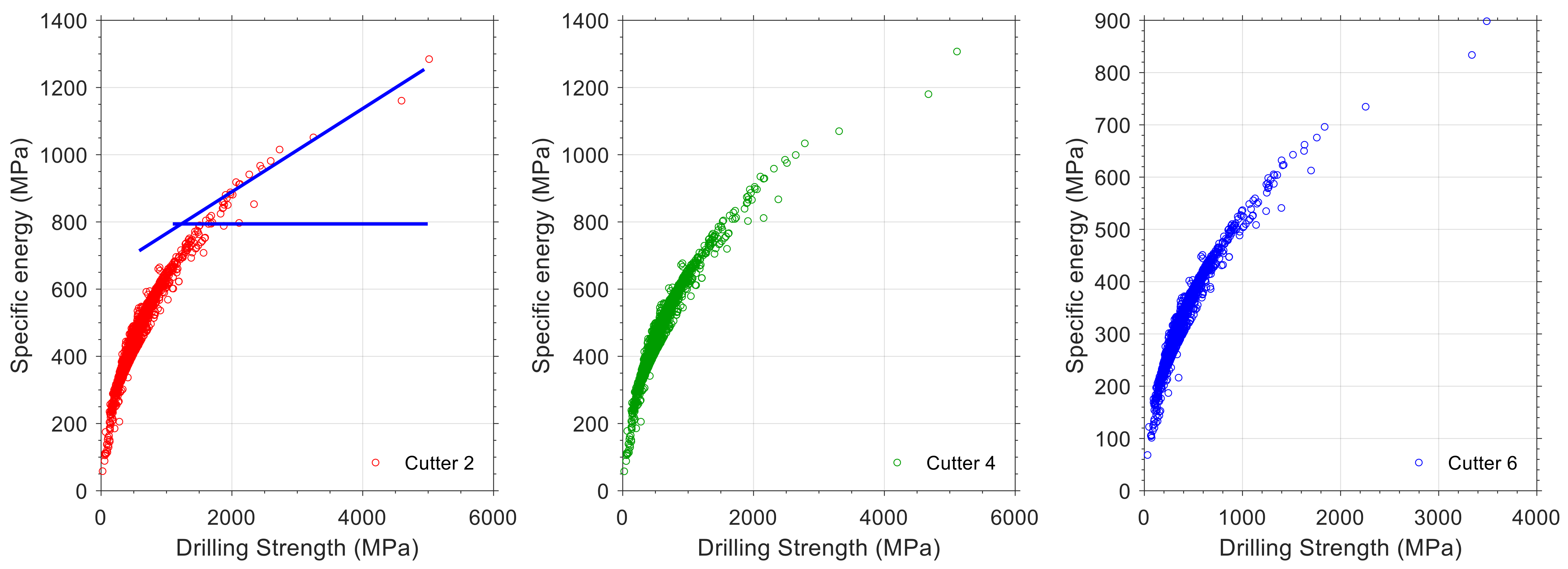
The results of torque and specific energy analysis in equivalent cutters for two bit runs are presented in Figure 17 and Figure 18. Taking into consideration the position of the equivalent cutters, all exhibit similar trends, but their specific energy and torque values differ. Similarly, the torque in all equivalent cutters (here equivalent cutters 1, 5, and 9 for bit number 1 and equivalent cutters 2, 4, and 6 for bit number 2) follows the same trend as the cutting force in Figure 15 and Figure 16. On the basis of Equation (10) and the rate of penetration data, specific energy is calculated at equivalent cutters. Based on the simulated data for bit run number 1, three distinct trends can be identified. It is significant to note that each of these trends represents variations in the downhole parameters or drilling dynamics. They could, for example, be related to changes in rock drillability or variations in downhole differential pressure. As a result, by measuring the annulus pressure near the drilling bit, it is possible to link such variations to rock drillability with a high degree of precision. The plots of specific energy versus drilling strength for both bit runs are shown in Figure 19 and Figure 20. It has been found that three trends are derived in Figure 19, which correspond to the trends in Figure 17. As there is no change in downhole pressure as a result of fluid loss or influx, these variations are caused by changes in the drillability of the rock. The interval for the second bit run has almost constant lithology, and therefore there is a single trend in the plots for specific energy and drilling strength.
Based on Figure 8, it is possible to perform a qualitative analysis of the status of the equivalent cutters. Using Figure 20, two tangential lines could be plotted and their location would provide insight into the status of the equivalent cutters during drilling. A plot of tangent lines is shown on the left side of this figure. Whatever data depart from the cutting point indicate that the friction surface below cutters dissipates higher energy while the wear surface below cutters is progressing. In Figure 20, most data points (specific energy and drilling strength) are below the cutting point, indicating that all equivalent cutters (cutter number 2, 4, and 6) are in good condition. In Figure 19, the same analysis could be performed on bit run number 1.
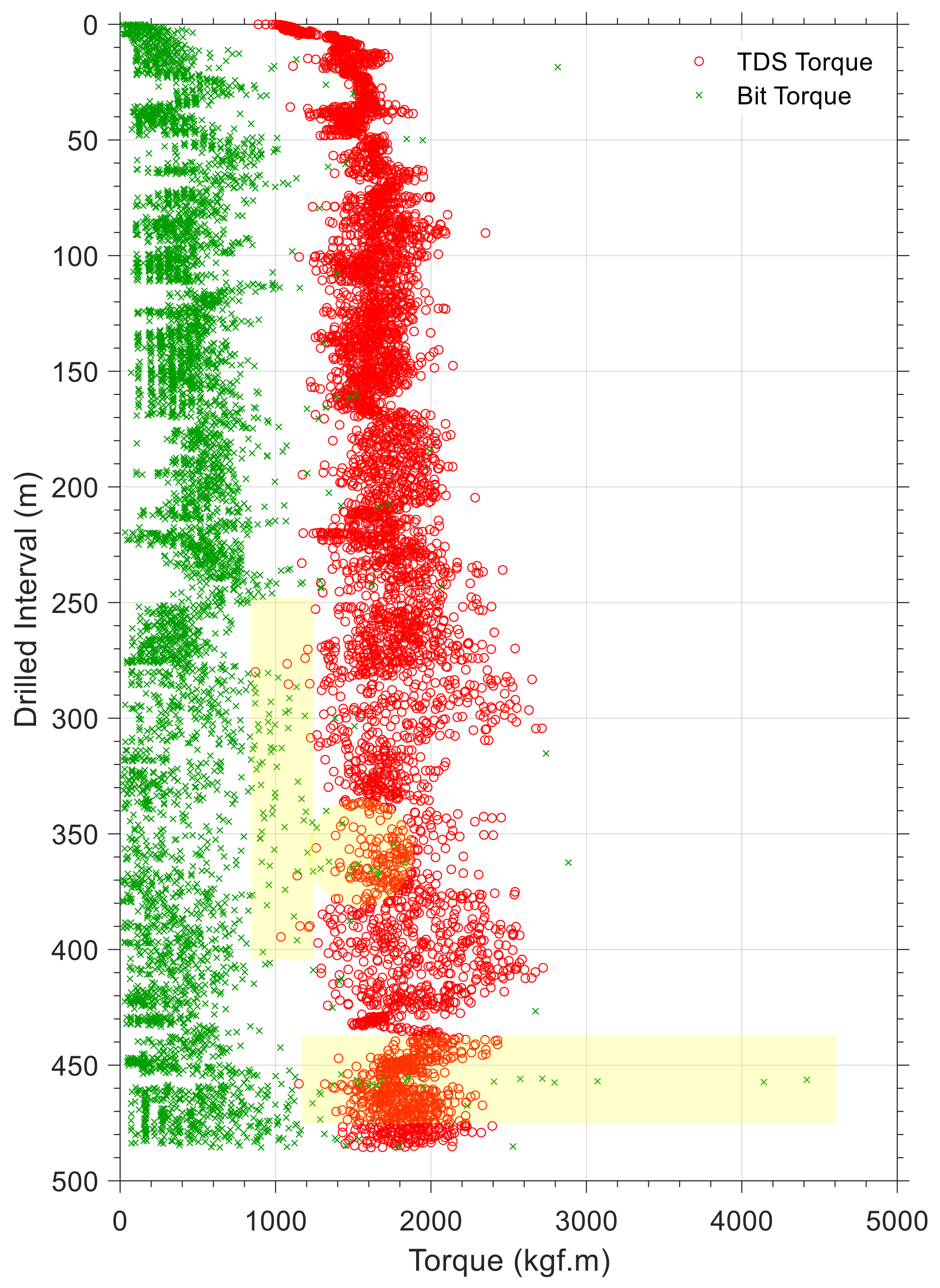
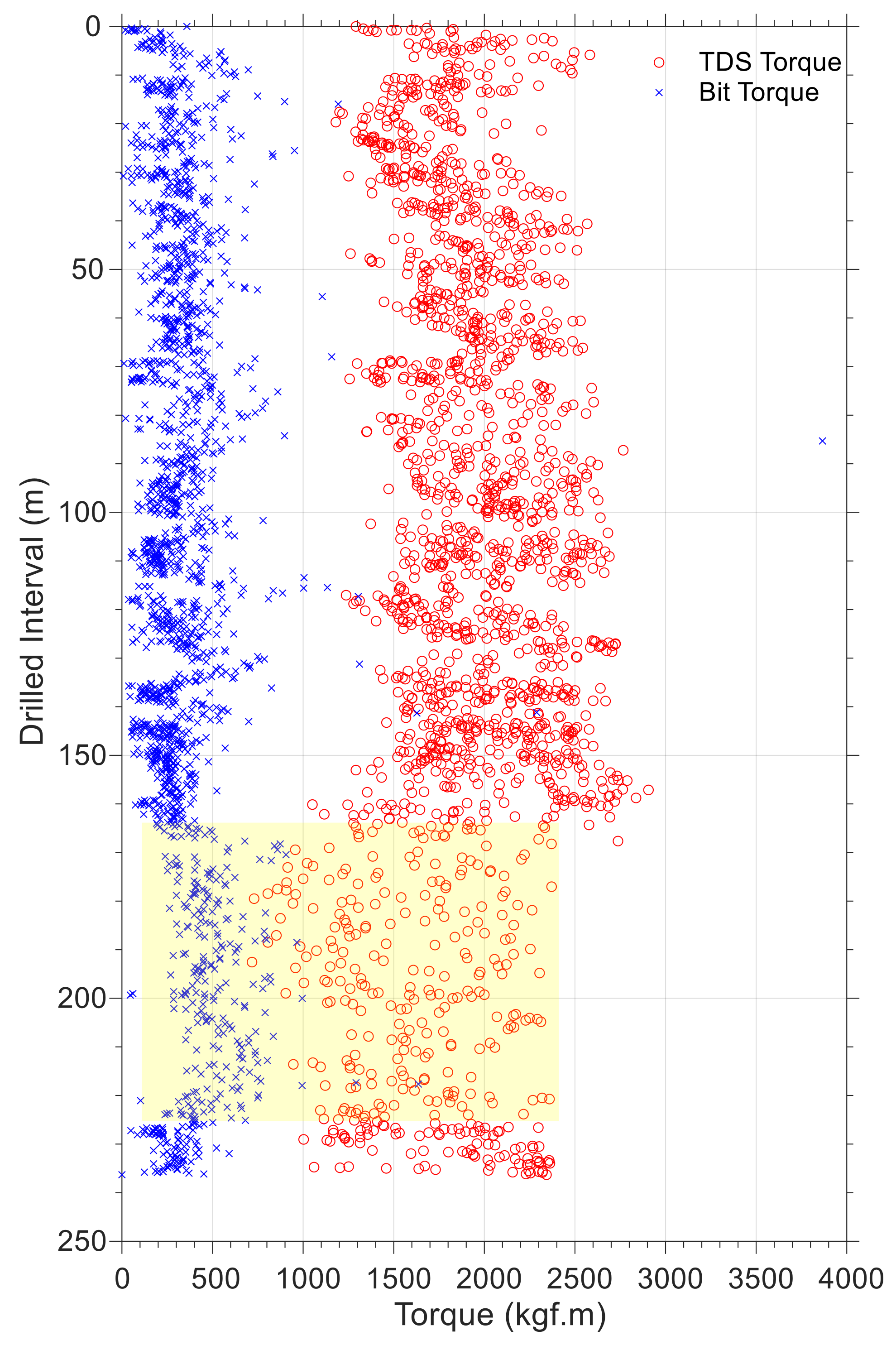
As there is no near-bit ASM sensor to measure the torque at the bit, having a cutter–rock interaction model provides an opportunity to scale up forces at equivalent cutters in order to calculate the torque at the bit. To understand drill string dynamics for possible downhole problems, it may be useful to compare the torque value to the torque delivered to the drill string at the surface or to the torque measured at other ASMs. Figure 21 and Figure 22 represent a comparison between the torque delivered by the top drive system and the torque calculated by the model. Data differences in each plot indicate the amount of energy dissipated by friction between the drill string and the borehole wall. Most of the section length in bit run number 1 is drilled horizontally, which explains why the difference between torque values at the end of the bit run (drilled interval greater than 450 m) is greater than other parts in this interval. As the horizontal section increases, the torque difference values should increase for the second bit run. As opposed to the general expected trend, according to the highlighted part in Figure 22, the difference between the torque at the bit and the torque at TDS has been significantly reduced. There could be several reasons for this, including improvements in drilling fluid lubricity or improved hole cleaning due to higher flow rates or fluid rheologies. Nevertheless, the most important thing is that it raises awareness among drilling crews when it comes to looking for possible reasons during drilling operations. There is a general perception that top drive torque is greater than the bit torque. Despite this, some intervals (for example highlighted section in Figure 21) have almost equal values or have higher bit torque values. The problem is caused by a phenomenon called stick-slip, whereby uncontrollable and accumulated torsional energy in the drill string (as a result of friction between the borehole wall and the drill string) is released at the bit before it is detectable at the surface. As a consequence, such signs indicate a need for better borehole cleaning during drilling.
5. Conclusions
Drill string and bit modeling in real time requires understanding of the forces and stresses experienced at the bit. Additionally, the distribution of forces at the cutters could provide an advanced application for determining the optimal design and placement of cutters. For the purpose of developing a cutter–rock interaction model, a total of 700 experimental data points were collected and a regression analysis was performed to correlate equations for normal and cutting forces. An ANOVA analysis of the data and correlations indicated that there is a strong correlation between the normal and the cutting forces and cutting area, rock drillability, differential pressure, and cutter design parameters, i.e., cutter diameter and back-rake angle.
A hybrid algorithm combining cutter–rock interaction models, drilling bit models, and data analytic technique has been developed to handle real-time noisy data. An analysis of drilling data demonstrated the applicability of the algorithm. Measurable drilling parameters including bit weight, torque, rotary speed, fluid pressure, temperature, and acceleration at the bit could provide knowledge about downhole dynamics. Among the applications of this algorithm are cutter placement design, real-time status evaluation of the drilling bit, vibrational analysis of the bit, identification of lithology, drill string dynamic analysis, and the detection of downhole problems. The downhole dynamics of the drill string and the drilling bit were investigated using drilling data for two bit runs from a well on the Norwegian continental shelf (NCS). The comparison of torque at the surface and torque at the bit uncovered possible problems, such as stick-slip and cuttings transport. The algorithm has been applied qualitatively to evaluate bit status and major changes in rock drillability. As a whole, such a physics-based data analytic approach constitutes a reliable method for diagnosing drilling events and symptoms in real time.
Author Contributions
Conceptualization, M.G. and B.E.; Methodology, M.G.; Data curation, B.E.; Writing—original draft, M.G. and B.E.; Supervision, B.E. All authors have read and agreed to the published version of the manuscript.
Funding
The APC was funded by Norwegian University of Science and Technology.
Acknowledgments
This research is a part of BRU21—NTNU Research and Innovation Program on Digital and Automation Solutions for the Oil and Gas Industry. (https://www.ntnu.edu/bru21), accessed on 4 October 2022.
Conflicts of Interest
The authors declare no conflict of interest.
Abbreviations
The following abbreviations are used in this manuscript:
| PDC | Polycrystalline diamond compact |
| ASM | Along-string measurement |
| EMS | Enhanced measurement system |
| TDS | Top drive system |
| SE | Specific energy |
| MSE | Mechanical specific energy |
| DS | Drilling strength |
| GA | Genetic algorithm |
| RLS | Recursive least square |
| ROP | Rate of penetration |
| NCS | Norwegian continental shelf |
References
- Zijsling, D.H. Single Cutter Testing—A Key for PDC Bit Development. In Proceedings of the SPE Offshore Europe, Aberdeen, UK, 8–11 September 1987; p. SPE-16529-MS. [Google Scholar] [CrossRef]
- Glowka, D.A. Use of Single-Cutter Data in the Analysis of PDC Bit Designs: Part 1—Development of a PDC Cutting Force Model. J. Pet. Technol. 1989, 41, 797–849. [Google Scholar] [CrossRef]
- Glowka, D.A. Use of Single-Cutter Data in the Analysis of PDC Bit Designs: Part 2—Development and Use of the PDC Wear Computer Code. J. Pet. Technol. 1989, 41, 850–859. [Google Scholar] [CrossRef]
- Detournay, E.; Defournay, P. A Phenomenological Model for the Drilling Action of Drag Bits. Int. J. Rock Mech. Sci. Geomech. Abstr. 1992, 29, 13–23. [Google Scholar] [CrossRef]
- Dagrain, F.; Detournay, E.; Richard, T. Influence of Cutter Geometry in Rock Cutting. In Proceedings of the DC Rocks 2001, The 38th U.S. Symposium on Rock Mechanics (USRMS), Washington, DC, USA, 7–10 July 2001; pp. 927–933. [Google Scholar]
- Detournay, E.; Richard, T.; Shepherd, M. Drilling Response of Drag Bits: Theory and Experiment. Int. J. Rock Mech. Min. Sci. 2008, 45, 1347–1360. [Google Scholar] [CrossRef]
- Rajabov, V.; Miska, S.; Mortimer, L.; Yu, M.; Ozbayoglu, E. The Effects of Back Rake and Side Rake Angles on Mechanical Specific Energy of Single PDC Cutters with Selected Rocks at Varying Depth of Cuts and Confining Pressures. In Proceedings of the IADC/SPE Drilling Conference and Exhibition, San Diego, CA, USA, 6–8 March 2012; p. SPE-151406-MS. [Google Scholar] [CrossRef]
- Rafatian, N.; Miska, S.; Ledgerwood, L.W.; Ahmed, R.; Yu, M.; Takach, N. Experimental Study of MSE of a Single PDC Cutter Interacting with Rock Under Simulated Pressurized Conditions. SPE Drill. Compl. 2009, 25, 10–18. [Google Scholar] [CrossRef]
- Chen, P.; Miska, S.; Ren, R.; Yu, M.; Ozbayoglu, E.; Takach, N. Poroelastic Modeling of Cutting Rock in Pressurized Condition. J. Pet. Sci. Eng. 2012, 169, 623–635. [Google Scholar] [CrossRef]
- Ledgerwood, L.W. PFC Modeling of Rock Cutting Under High Pressure Conditions. In Proceedings of the 1st Canada–U.S. Rock Mechanics Symposium, Vancouver, BC, Canada, 27–31 May 2007; p. ARMA-07-063. [Google Scholar]
- Akbari, B.; Miska, S.; Yu, M.; Rahmani, R. The Effects of Size, Chamfer Geometry, and Back Rake Angle on Frictional Response of PDC Cutters. In Proceedings of the 48th U.S. Rock Mechanics/Geomechanics Symposium, Minneapolis, MN, USA, 1–4 June 2014; p. ARMA-2014-7458. [Google Scholar]
- Akbari, B.; Miska, S.; Yu, M.; Ozbayoglu, M. Experimental Investigations of the Effect of the Pore Pressure on the MSE and Drilling Strength of a PDC Bit. In Proceedings of the SPE Western North American and Rocky Mountain Joint Meeting, Denver, CO, USA, 17–18 April 2014; p. SPE-169488-MS. [Google Scholar] [CrossRef]
- Grima, M.A.; Miedema, S.A.; Van de Ketterij, R.G.; Yenigül, N.B.; Van Rhee, C. Effect of High Hyperbaric Pressure on Rock Cutting Process. Eng. Geol. 2015, 196, 24–36. [Google Scholar] [CrossRef]
- Detournay, E.; Atkinson, C. Influence of Pore Pressure on the Drilling Response in Low Permeability Shear Dilatant Rocks. Int. J. Rock Mech. Min. Sci. 2000, 37, 1091–1101. [Google Scholar] [CrossRef]
- Erguo, L.; Wang, J.; Zhou, L.; Wang, L. The Analysis of Force on PDC Cutter. In Energy Materials 2014; Springer: Cham, Switzerland, 2014; pp. 781–787. [Google Scholar]
- Wang, J.W.; Deyonga, Z.; Renqinga, H. Experimental Study on Force of PDC Cutter Breaking Rock. Procedia Eng. 2014, 73, 258–263. [Google Scholar] [CrossRef]
- Coudyzer, C.; Richard, T. Influence of the Back and Side Rake Angles in Rock Cutting. In Proceedings of the AADE 2005 National Technical Conference and Exhibition, Houston, TX, USA, 5–7 April 2005; p. AADE-05NTCE-75. [Google Scholar]
- Liu, J.; Zheng, H.; Kuang, Y.; Xie, H.; Qin, C. 3D Numerical Simulation of Rock Cutting of an Innovative Non-Planar Face PDC Cutter and Experimental Verification. Appl. Sci. 2019, 9, 4372. [Google Scholar] [CrossRef] [Green Version]
- Goshouni, M.; Richard, T. Effect of Back Rake Angle and Groove Geometry in Rock Cutting. In Proceedings of the ISRM International Symposium—5th Asian Rock Mechanics Symposium, Tehran, Iran, 24–26 November 2008; p. ISRM-ARMS5-2008-027. [Google Scholar]
- Huang, Z.; Ma, Y.; Li, Q.; Xie, D. Geometry and Force Modeling, and Mechanical Properties Study of Polycrystalline Diamond Compact Bit Under Wearing Condition Based on Numerical Analysis. Adv. Mech. Eng. 2017, 9, 1–15. [Google Scholar] [CrossRef] [Green Version]
- Chen, P.; Meng, M.; Miska, S.; Yu, M.; Ozbayoglu, E.; Takach, N. Study on Integrated Effect of PDC Double Cutters. J. Pet. Sci. Eng. 2019, 178, 1128–1142. [Google Scholar] [CrossRef]
- Zhu, X.; Deng, Z.; Liu, W. Experimental Study on Energy Consumption of Rock Cutting Under Different Groove Geometry. Geotech. Test. J. 2020, 43, 151–170. [Google Scholar] [CrossRef]
- Pryhorovska, T.O. Study on Rock Reaction Force Depending on PDC Cutter Placement. Mach. Sci. Tech. 2017, 21, 37–66. [Google Scholar] [CrossRef]
- Ai, Z.; Han, Y.; Kuang, Y.; Wang, Y.; Zhang, M. Optimization Model for Polycrystalline Diamond Compact Bits Based on Reverse Design. Adv. Mech. Eng. 2018, 10, 1–12. [Google Scholar] [CrossRef]
- Zhou, Y.; Detournay, E. Analysis of The Contact Forces on a Blunt PDC Bit. In Proceedings of the 48th U.S. Rock Mechanics/Geomechanics Symposium, Minneapolis, MN, USA, 1–4 June 2014; p. ARMA-2014-7351. [Google Scholar]
- Rostamsowlat, I.; Richard, T.; Evans, B. Experimental Investigation on the Effect of Wear Flat Inclination on The Cutting Response of a Blunt Tool in Rock Cutting. Acta Geotech. 2019, 14, 519–534. [Google Scholar] [CrossRef]
- Dagrain, F.; Richard, T. On The Influence of PDC Wear and Rock Type on Friction Coefficient and Cutting Efficiency. In Eurock 2006: Multiphysics Coupling and Long Term Behaviour in Rock Mechanics; CRC Press: Boca Raton, FL, USA, 2006. [Google Scholar] [CrossRef]
- Sinor, A.; Warren, T.M. Drag Bit Wear Model. SPE Drill. Eng. 1989, 4, 128–136. [Google Scholar] [CrossRef]
- Chandong, C.; Zoback, M.D.; Khaksar, A. Empirical Relations between Rock Strength and Physical Properties in Sedimentary Rocks. J. Pet. Sci. Eng. 2006, 51, 223–237. [Google Scholar] [CrossRef]
- Andrews, R.; Hareland, G.; Nygaard, R.; Engler, T.; Munro, H.; Virginillo, B. Methods of Using Logs to Quantify Drillability. In Proceedings of the Rocky Mountain Oil & Gas Technology Symposium, Denver, CO, USA, 16–18 April 2007; p. SPE-106571. [Google Scholar] [CrossRef]
- Yari, M.; Bagherpour, R. Investigating an Innovative Model for Dimensional Sedimentary Rocks Characterization Using Acoustic Frequencies Analysis during Drilling. Rud.-GeološKo-Naft. Zb. 2018, 33, 17–25. [Google Scholar] [CrossRef] [Green Version]
- Che, D.; Zhang, W.; Ehmann, K.F. Rock-cutter Interactions in Linear Rock Cutting. In Proceedings of the ASME 2016 11th International Manufacturing Science and Engineering Conference, Blacksburg, VA, USA, 27 June–1 July 2016. [Google Scholar]
- Bourgoyne, A.T.; Young, F.S. A Multiple Regression Approach to Optimal Drilling and Abnormal Pressure Detection. SPE J. 1974, 14, 371–384. [Google Scholar] [CrossRef]
- Warren, T.M. Penetration Rate Performance of Roller Cone Bits. SPE Drill. Eng. 1987, 2, 9–18. [Google Scholar] [CrossRef]
- Rashidi, B.; Hareland, G.; Tahmeen, M.; Anisimov, M.; Abdorazakov, S. Real Time Bit Wear Optimization Using the Intelligent Drilling Advisory System. In Proceedings of the SPE Russian Oil and Gas Conference and Exhibition, Moscow, Russia, 26–28 October 2010; p. SPE-136006. [Google Scholar] [CrossRef]
- Hussain, R. Specific Energy as a Criterion for Bit Selection. J. Pet. Technol. 1985, 37, 1225–1229. [Google Scholar] [CrossRef]
- Dupriest, F.E.; Koederitz, L.W. Maximizing Drill Rates with Real-Time Surveillance of Mechanical Specific Energy. In Proceedings of the SPE/IADC Drilling Conference, Amsterdam, The Netherlands, 23–25 February 2005; p. SPE-92194-MS. [Google Scholar] [CrossRef]
- Mohan, K.; Adil, F.; Samuel, R. Comprehensive Hydromechanical Specific Energy Calculation for Drilling Efficiency. J. Energy Resour. Technol. 2015, 137, 012904. [Google Scholar] [CrossRef]
- Waughman, R.J.; Kenner, J.V.; Moore, R.A. Real-Time Specific Energy Monitoring Enhances the Understanding of When to Pull Worn PDC Bits. SPE Drill. Compl. 2002, 18, 59–67. [Google Scholar] [CrossRef]
- Bjornsson, E.; Hucik, B.; Szutiak, G.; Brown, L.A.; Evans, H.; Curry, D.; Perry, P. Drilling Optimization Using Bit Selection Expert System and ROP Prediction Algorithm Improves Drilling Performance and Enhances Operational Decision Making by Reduction Performance Uncertainties. In Proceedings of the SPE Annual Technical Conference and Exhibition, Houston, TX, USA, 26–29 September 2004; p. SPE-90752. [Google Scholar] [CrossRef]
- Caicedo, H.U.; Calhoun, W.M.; Ewy, R.T. Unique ROP Predictor Using Bit-Specific Coefficient of Sliding Friction and Mechanical Efficiency as a Function of Confined Compressive Strength Impacts Drilling Performance. In Proceedings of the SPE/IADC Drilling Conference, Amsterdam, The Netherlands, 23–25 February 2005; p. SPE/IADC92576. [Google Scholar] [CrossRef]
- Teale, R. The Concept of Specific Energy in Rock Drilling. Int. J. Rock Mech. Min. Sci. 1965, 2, 57–73. [Google Scholar] [CrossRef]
- Liang, E.G.; Li, Z.F.; Zou, D.Y. Experimental Research on Integrated Mechanical Model of PDC Bit. Rock Soil. Mech. 2009, 18, 938–942. [Google Scholar]
- Richard, T.; Coudyzer, C.; Desmette, S. Influence of Groove Geometry and Cutter Inclination in Rock Cutting. In Proceedings of the 44th U.S. Rock Mechanics Symposium and 5th U.S.–Canada Rock Mechanics Symposium, Salt Lake City, UT, USA, 27–30 June 2010; p. ARMA-10-429. [Google Scholar]
- Majidi, R.; Miska, S.; Tammineni, T. PDC single Cutter: The Effects of Depth of Cut and RPM Under Simulated Borehole Conditions. Wiert. Naft. Gaz 2011, 1, 283–295. [Google Scholar]
- Akbari, B.; Miska, S. Relative Significance of Multiple Parameters on the Mechanical Specific Energy and Frictional Responses of Polycrystalline Diamond Compact Cutters. ASME J. Energy Resour. Technol. 2017, 139, 022904. [Google Scholar] [CrossRef]
- Akbari, B.; Miska, S. The Effects of Chamfer and Back Rake Angle on PDC Cutters Friction. J. Nat. Gas Sci. Eng. 2016, 35, 347–353. [Google Scholar] [CrossRef]
- Appl, F.C.; Wilson, C.; Lakshman, I. Measurement of Forces, Temperatures and Wear of PDC Cutters in Rock Cutting. Wear 1993, 169, 9–24. [Google Scholar] [CrossRef]
- Chollet, F. Deep Learning with Python, 2nd ed.; Manning Publications Co.: New York, NY, USA, 2018. [Google Scholar]
- Simon, R. Energy Balance in Rock Drilling. SPE J. 1963, 3, 298–306. [Google Scholar] [CrossRef]
- Gerbaud, L.; Menand, S.; Sellami, H. PDC Bits: All Comes from the Cutter-Rock Interaction. In Proceedings of the IADC/SPE Drilling Conference, Miami, FL, USA, 21–23 February 2006; p. IADC/SPE-98988. [Google Scholar] [CrossRef]
- Simon, D. Optimal State Estimation, Kalman Filter, H Infinity and Nonlinear Approaches; John Wiley & Sons, Inc.: Hoboken, NJ, USA, 2006. [Google Scholar]
- Ma, Y.; Lian, Z.; Huang, Z.; Zhang, W.; Xie, D. Optimal Design of a Dlobal Force-Balanced Polycrystalline Diamond Compact Bit Considering Wear Condition. Adv. Mech. Eng. 2019, 11, 1–20. [Google Scholar] [CrossRef]
Figure 1.
Geometry parameters for dull cutter.

Figure 2.
Geometry parameters for new cutter.

Figure 3.
Scatter plot of experimental and estimated values by K-fold cross validation during training of the deep learning network.
Figure 3.
Scatter plot of experimental and estimated values by K-fold cross validation during training of the deep learning network.

Figure 4.
Geometrical parameters of a single cutter defined as back-rake () and side-rake () angles.
Figure 4.
Geometrical parameters of a single cutter defined as back-rake () and side-rake () angles.

Figure 5.
Sample PDC bit and the equivalent blade representation of the cutters; r, z, and w indicate the coordinate axis in radial, normal, and tangential directions, respectively; C is the bit profile curve; n is the normal direction to the bit profile and is the angle between normal to the bit profile and bit axis.

Figure 6.
(a) Traces of all cutters on a vertical plane. (b) Equivalent blade produced by traces of cutters involved in drilling depth, d, in one revolution and discretization of equivalent blade into equivalent rectangular cutters. (c) Spatial position of cutters in two successive revolutions.
Figure 6.
(a) Traces of all cutters on a vertical plane. (b) Equivalent blade produced by traces of cutters involved in drilling depth, d, in one revolution and discretization of equivalent blade into equivalent rectangular cutters. (c) Spatial position of cutters in two successive revolutions.

Figure 7.
(a) The framework of equivalent rectangular cutters formed by the overlapping of complete or partial circular cutters and (b) schematic of an equivalent cutter composed of several partial cutters.
Figure 7.
(a) The framework of equivalent rectangular cutters formed by the overlapping of complete or partial circular cutters and (b) schematic of an equivalent cutter composed of several partial cutters.

Figure 8.
Graphical representation of specific energy and drilling strength. Marker data are calculated based on drilling measurement data utilized in this study, and solid lines are tangent to these data to build cutting and friction lines.
Figure 8.
Graphical representation of specific energy and drilling strength. Marker data are calculated based on drilling measurement data utilized in this study, and solid lines are tangent to these data to build cutting and friction lines.

Figure 9.
Force decomposition on a single cutter along tangential and normal directions.

Figure 10.
Schematic of wear height and wear flat area of a blunt cutter. The hatched area indicates the worn section of the cutter.
Figure 10.
Schematic of wear height and wear flat area of a blunt cutter. The hatched area indicates the worn section of the cutter.

Figure 11.
Scatter plot of experimental data and the calculated values by the regression methods for normal force.
Figure 11.
Scatter plot of experimental data and the calculated values by the regression methods for normal force.

Figure 12.
Scatter plot of experimental data and the calculated values by the regression methods for cutting force.
Figure 12.
Scatter plot of experimental data and the calculated values by the regression methods for cutting force.

Figure 13.
Normal distribution of normal force concluded from experimental data and the results of regression by non-linear regression and deep learning methods.
Figure 13.
Normal distribution of normal force concluded from experimental data and the results of regression by non-linear regression and deep learning methods.

Figure 14.
Normal distribution of cutting force concluded from experimental data and the results of regression by non-linear regression and deep learning methods.
Figure 14.
Normal distribution of cutting force concluded from experimental data and the results of regression by non-linear regression and deep learning methods.

Figure 15.
Specific energy (left) and torque (right) plots for bit run number 1 for three equivalent cutters; i.e., 1, 5, and 9.
Figure 15.
Specific energy (left) and torque (right) plots for bit run number 1 for three equivalent cutters; i.e., 1, 5, and 9.

Figure 16.
Specific energy (left) and torque (right) plots for the bit run number 2 for three equivalent cutters; i.e., 1, 5, and 9.
Figure 16.
Specific energy (left) and torque (right) plots for the bit run number 2 for three equivalent cutters; i.e., 1, 5, and 9.

Figure 17.
Specific energy (left) and torque (right) plots at the bit during bit run number 1.

Figure 18.
Specific energy (left) and torque (right) plots at the bit during bit run number 2.

Figure 19.
Specific energy for the drilled interval in bit run number 1. Each plot is for a specific equivalent cutter which is written as legend.
Figure 19.
Specific energy for the drilled interval in bit run number 1. Each plot is for a specific equivalent cutter which is written as legend.

Figure 20.
Specific energy for the drilled interval in bit run number 2. Each plot is for a specific equivalent cutter which is written as legend.
Figure 20.
Specific energy for the drilled interval in bit run number 2. Each plot is for a specific equivalent cutter which is written as legend.

Figure 21.
Torque at bit and torque delivered to the drill string at the surface for bit run number 1.
Figure 21.
Torque at bit and torque delivered to the drill string at the surface for bit run number 1.

Figure 22.
Torque at bit and toque delivered to the drill string at the surface for bit run number 2.
Figure 22.
Torque at bit and toque delivered to the drill string at the surface for bit run number 2.

Table 2.
Summary of experimental data implemented in regression: , normal force, , cutting force.
| References | No. of Data in | Cutter | Cutter Size | Back-Rake | |
|---|---|---|---|---|---|
| Condition | (mm) | Angle (°) | (psi) | ||
| Rajabov et al. [7] | 40, 117 | New | 13 | 10, 20, 30, 40 | 0, 250, 500 |
| Glowka [2,3] | 403, 403 | New, Dull | 12.7, 19 | 20 | 0 |
| Akbari et. al. [11,12] | 64, 67 | New | 13, 16 | 20 | 450 |
| Richard et al. [44] | 0, 50 | New | 13, 19 | 15 | 0 |
| Majidi et al. [45] | 54, 54 | New | 13 | 15 | 0, 50, 150, 250 |
| Wang et al. [16] | 93, 88 | New | 13 | 5, 10, 15, 20, 25 | 0 |
Table 3.
Statistical summary of experimental data employed in regression of (Number of observations 654).
Table 3.
Statistical summary of experimental data employed in regression of (Number of observations 654).
| Variable | Mean | Standard Deviation | Minimum | Maximum |
|---|---|---|---|---|
| Normal Force (N) | 2124.7 | 1957.33 | 59.16 | 7893.36 |
| Cutter Diameter (mm) | - | - | 12.7 | 19.05 |
| Cutting Area (mm2) | 9.19 | 8.08 | 0.1 | 49.5 |
| Wear Flat Area (mm2) | 10.78 | 10.58 | 0 | 25.8 |
| Back-Rake Angle (deg) | - | - | 5 | 40 |
| Cutter Wear Height (mm) | 0.68 | 0.65 | 0 | 1.69 |
| Rock Drillability, K | 5.46 | 0.94 | 3.2 | 7.78 |
| (dimensionless) | ||||
| Differential Pressure (psi) | 52.67 | 136.81 | 0 | 450 |
Table 4.
Statistical summary of experimental data employed in regression of (Number of observations 779).
Table 4.
Statistical summary of experimental data employed in regression of (Number of observations 779).
| Variable | Mean | Standard Deviation | Minimum | Maximum |
|---|---|---|---|---|
| Cutting Force (N) | 1382.48 | 1224.54 | 11.41 | 5747.19 |
| Cutter Diameter (mm) | - | - | 12.7 | 19.05 |
| Cutting Area (mm2) | 8.53 | 7.56 | 0.11 | 37.92 |
| Wear Flat Area (mm2) | 9.05 | 10.47 | 0 | 25.8 |
| Back-Rake Angle (deg) | - | - | 5 | 40 |
| Cutter Wear Height (mm) | 0.57 | 0.65 | 0 | 1.69 |
| Rock Drillability, K | 5.36 | 1.07 | 3.2 | 7.78 |
| (dimensionless) | ||||
| Differential Pressure (psi) | 78.32 | 156.88 | 0 | 500 |
Table 6.
Regression analysis for correlation of cutting force.
| Source | SS | df | MS | F–Factor |
|---|---|---|---|---|
| Regression () | 745.727 | 6 | 149.145 | 505.576 |
| Residual | 228.083 | 772 | 0.295 | |
| Total | 973.810 | 778 | 1.251 |
Table 7.
Regression analysis for correlation of normal force.
| Source | SS | df | MS | F–Factor |
|---|---|---|---|---|
| Regression () | 4736.6 | 6 | 789.434 | 1652.53 |
| Residual | 309.08 | 647 | 0.4771 | |
| Total | 5045.68 | 653 | 7.7269 |
Table 8.
Regression coefficients of cutting force along with t-test and p values.
| Cutting Force () | Coef. | Std. Err. | t-Stat | p-Value | 95% Confidence Interval | |
|---|---|---|---|---|---|---|
| 0.2469 | 0.1821 | 1.3558 | 0.004 | 0.1632 | 0.8782 | |
| 0.5237 | 0.0216 | 24.2453 | 0.001 | 0.5 | 0.7370 | |
| 0.7454 | 0.0562 | 13.2633 | 0.0 | 0.6013 | 0.8347 | |
| 0.1 | — | — | — | — | — | |
| 0.6432 | — | — | — | — | — | |
| 2.6821 | 0.0947 | 28.3220 | 0.0 | 2.4564 | 2.8283 | |
| 0.5173 | 0.0387 | 13.3669 | 0.0 | 0.3789 | 0.5310 | |
| 0.4 | — | — | — | — | — | |
| 1.0 | — | — | — | — | — | |
* As a lower bound was set for the variable, ANOVA is not available. ** Coefficient considered as constant for ANOVA analysis. *** As an upper bound was set for the variable, ANOVA is not available.
Table 9.
Regression coefficients of normal force along with t-test and p values.
| Cutting Force () | Coef. | Std. Err. | t-Stat | p-Value | 95% Confidence Interval | |
|---|---|---|---|---|---|---|
| 0.0 | — | — | — | — | — | |
| 1.2826 | 0.3836 | 3.34 | 0.001 | 0.5294 | 2.0358 | |
| 0.4524 | 0.0288 | 15.7083 | 0.0 | 0.4308 | 0.4776 | |
| 0.1 | — | — | — | — | — | |
| 0.7055 | — | — | — | — | — | |
| 3.2531 | 0.0714 | 45.5616 | 0.0 | 3.0342 | 3.5148 | |
| 0.2958 | 0.0603 | 4.9054 | 0.002 | 0.2 | 0.3044 | |
| 0.4 | — | — | — | — | — | |
| 1.0 | — | — | — | — | — | |
* As a lower bound was set for the variable, ANOVA is not available. ** Coefficient considered as constant for ANOVA analysis. *** As an upper bound was set for the variable, ANOVA is not available.
Publisher’s Note: MDPI stays neutral with regard to jurisdictional claims in published maps and institutional affiliations. |
© 2022 by the authors. Licensee MDPI, Basel, Switzerland. This article is an open access article distributed under the terms and conditions of the Creative Commons Attribution (CC BY) license (https://creativecommons.org/licenses/by/4.0/).
Share and Cite
MDPI and ACS Style
Gomar, M.; Elahifar, B. Application of Digitalization in Real-Time Analysis of Drilling Dynamics Using Along-String Measurement (ASM) Data along Wired Pipes. Energies 2022, 15, 8930. https://0-doi-org.brum.beds.ac.uk/10.3390/en15238930
AMA Style
Gomar M, Elahifar B. Application of Digitalization in Real-Time Analysis of Drilling Dynamics Using Along-String Measurement (ASM) Data along Wired Pipes. Energies. 2022; 15(23):8930. https://0-doi-org.brum.beds.ac.uk/10.3390/en15238930
Chicago/Turabian StyleGomar, Mostafa, and Behzad Elahifar. 2022. "Application of Digitalization in Real-Time Analysis of Drilling Dynamics Using Along-String Measurement (ASM) Data along Wired Pipes" Energies 15, no. 23: 8930. https://0-doi-org.brum.beds.ac.uk/10.3390/en15238930
Note that from the first issue of 2016, this journal uses article numbers instead of page numbers. See further details here.