
A New Decentralized Space Vector PWM Method for Multilevel Single-Phase Full Bridge Converters


1
Faculty of Electrical and Electronics Engineering, Ho Chi Minh City University of Technology (HCMUT), 268 Ly Thuong Kiet Street, District 10, Ho Chi Minh City 70000, Vietnam
2
Vietnam National University Ho Chi Minh City, Vietnam Linh Trung Ward, Thu Duc District, Ho Chi Minh City 70000, Vietnam
3
Department of Electrical and Electronics Engineering, Ho Chi Minh City University of Food Industry, 140 Le Trong Tan Street, Tan Phu District, Ho Chi Minh City 70000, Vietnam
*
Author to whom correspondence should be addressed.
Energies 2022, 15(3), 1010; https://0-doi-org.brum.beds.ac.uk/10.3390/en15031010
Submission received: 8 January 2022
/
Revised: 23 January 2022
/
Accepted: 26 January 2022
/
Published: 29 January 2022
(This article belongs to the Special Issue Multilevel Converter Topology, Design, and Applications)
Abstract
:This paper proposes a decentralized control structure and method for a multilevel single-phase power converter using space vector pulse width modulation (SVPWM). The focus of this paper is on the decentralized control structure for the power converter cells that will exchange information with neighboring cells in order to adjust the switching vector and switching time for each cell. In this study, the switching vectors and the corresponding switching times of each cell will be self-determined based on the phase angle of two neighboring cells. Normally, SVPWM applied to the multilevel power converters need complete information about the total cells and cell’s position to build a control algorithm. Meanwhile, a decentralized space vector pulse width modulation (DSVPWM) method is proposed that can be applied to power converters with any number of cells and can be considered as a multilevel SVPWM method. In addition, the decentralized multilevel single-phase power converter has high flexibility with which it is possible to easily adjust the number of active cells, so that the output voltage can be adjusted quickly; this provides the ability to dynamically reconfigure without interrupting the power energy supply process. The proposed control structure and method are effectively verified based on simulation and experimental results. Experimental results are evaluated based on a 9-level single-phase power converter, which has an RL load with rated parameters 220 V/500 W.
1. Introduction
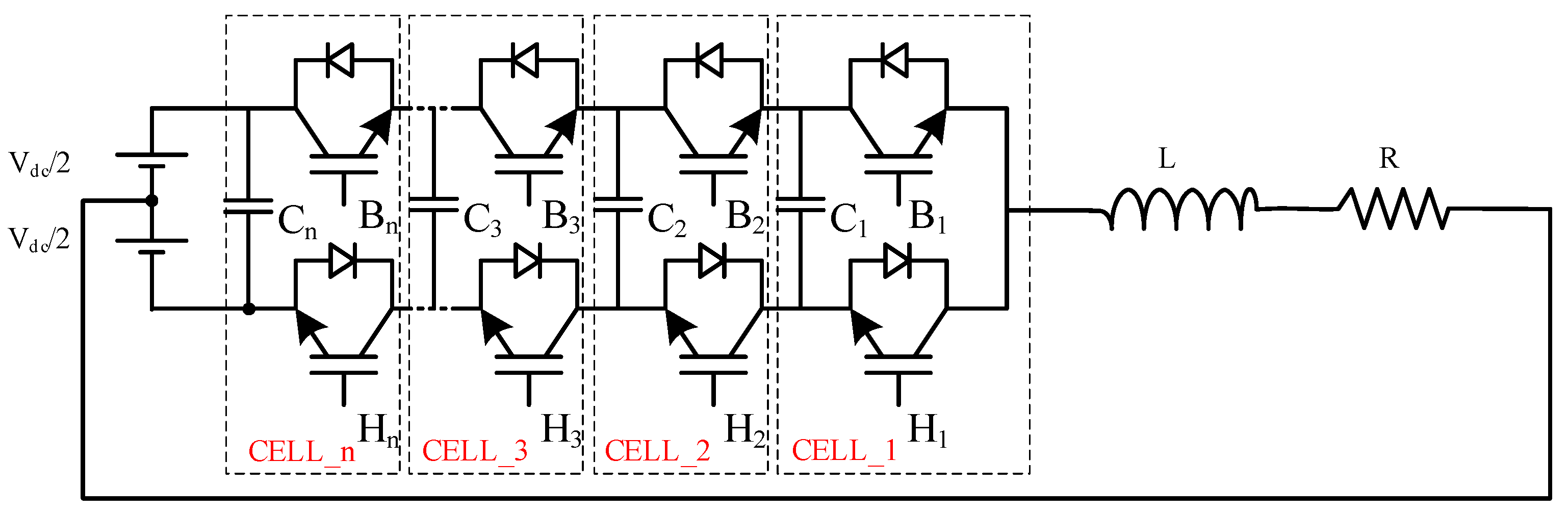
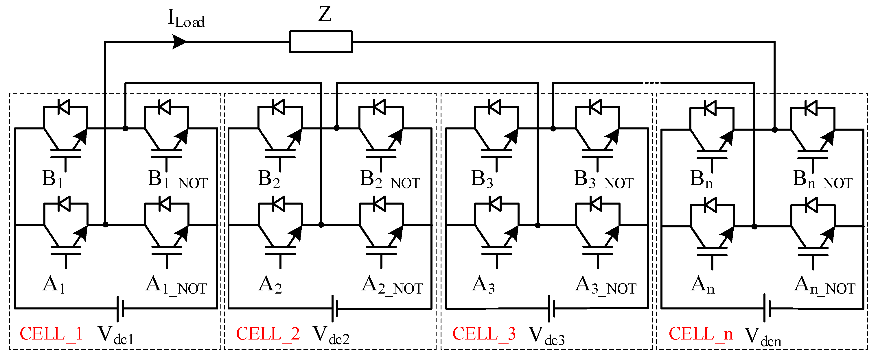
Multilevel power converters are increasingly popular and are widely applied in many fields and different applications [1,2]. The application of these power converters allows for increasing the efficiency of the energy conversion process, improving the output voltage quality, reducing the output voltage distortion, reducing the switching power loss of components, increasing the switching efficiency of the component, and reducing the switching voltage of the component [3,4,5,6]. The emergence of the modular multilevel converter (MMC) is one of the next generation multilevel converters for medium and high powers demands [3,7,8,9,10]. Figure 1 and Figure 2 present the topology for multilevel single-phase power converters [11,12]. By connecting cells in series, it is possible to adjust the output voltage according to the requirements of the load, which can expand the system’s ability to work with different voltage levels or increase flexibility in terms of control and operation [12,13,14,15].
Modular power converters typically use a processor as the central controller [16,17,18,19,20]. The central controller will receive feedback about the current, voltage of cells and branches [19,21,22]. Depending on the topology, control method and quality requirements, the central processor will calculate the phase angle and carrier amplitude suitable for the carrier pulse width modulation method [23]; this is achieved by the switching vector and switching time for space vector modulation and transmitting control signals to cells and IGBTs [24,25,26,27,28]. If the number of modulation voltage levels increases, the number of cells will increase, leading to a significant increase in the number of connections and control signals, requiring the central controller to have a very strong processing ability and a large number of inputs and outputs. The central processor may have a relatively high cost. In addition, during operation, the system may need to be reconfigured. The reasons may be that there are one or several damaged cells, impacting on the optimized conditions in control and operation. Then, the system needs to be able to add or remove some cells. For power converters using a central processor, this will be very difficult and the system can take a relatively long time to recover.
Currently, in order to maximize the advantages of multicell power converters, they are designed and controlled according to a decentralized control structure. Recent studies on this topic have highlighted the outstanding advantages of power converters that are designed and controlled according to a decentralized control model [12,13,14,15,29,30]. The decentralized control power converter can expand the ability to work with different voltage and power to meet the needs in terms of control and operation. This will be a very high advantage that classical power converters cannot achieve, or there will be certain difficulties in such classical power converters being able to achieve the same result. In such a case, the capacity of the power converter can be managed easily and quickly by adding or removing the number of modules in parallel or/and in series [15,30,31].
The structure, connection and control method of decentralized power converters have been studied and published in three main directions. Decentralized control has a hierarchical structure of two control levels, such as a controller master-slave, master-slave controller or local-central controller [32,33,34,35]. Each module of the decentralized power converter operates independently on its own voltage and current information, without communicating with neighboring modules [36,37]. The cells of the power converter exchange information with neighboring cells [14,15,29,30,31]. In particular, the control structure in which cells exchange information with neighboring cells is very suitable for control and expansion when used as needed.
The system is capable of dynamic reconfiguring, rebalancing when adding or removing some modules, or can easily replace a damaged module when necessary [12,13,14,15,29,30,31]. The system can easily and quickly reach a steady state under new conditions when the power converter structure is changed; this ensures that the system works continuously and without interruption. This is an extremely important and necessary feature in the study of decentralized power converters, as well as in a power supply system in which there are many decentralized power supplies in a grid.
Since the appearance of multilevel power converters, multilevel models have been introduced, such as diode-clamped converters (DCC) [38], flying capacitor converters (FCC) [39,40,41,42], full bridge converters, half bridge converters, etc. [38,43]. In addition, several power converter structures have been improved to have reduced switching components, reducing the total harmonic distortion and changing the current shape [44]. In control techniques for MMCs, the nearest level control (NLC) method is one of the most popular modulations [45]. Outstanding NLC method in low switching frequency modulation [46], used as a control method for the structure, involves a cascade full bridge multilevel inverter [47], MMC half bridge converter [48], and some improved structure [49,50]. The nearest level control method is also combined with the PWM method as a modulation algorithm for the MMCs [51]. Among them, full bridge configurations are well suited for the design of modular multilevel power converters. Typically, these power converters are introduced as three-phase power converters, but can be calibrated to operate as single-phase power converters. In fact, single-phase power converters also have a wide range of applications, especially for small and medium power demands [52,53,54].
Normally, switching pulses for multilevel power converters are modulated by two methods: carrier pulse width modulation [12,13,14] and space vector pulse width modulation [43,55]. Usually, in a full bridge configuration, the carrier level-shifted pulse width modulation is used as the primary method [13,14]. Meanwhile, the carrier pulse width modulation method is commonly based on the analog technique and does not have a common algorithm for all configurations. In contrast, the space vector pulse width modulation method stands out for providing considerable flexibility for optimizing switching waveforms and is well suited for digital implementations [9]. The first study and publication using the space vector modulation method for the multilevel multiphase power converter has proven the feasibility for this research direction [11]. This study presented the implementation of a decentralized control solution for a multiphase, multilevel inverter. Each phase is connected by full bridge cells in series. The space vector modulation algorithm for each cell is converted from a multiphase, multilevel modulation problem to a 2-level multiphase modulation problem [9]. After obtaining the results of 2-level, multiphase modulation, the system will refer to multilevel, multiphase modulation. The communication method used in the study is designed so that each cell communicates with two adjacent cells and can exchange information, such as phase angle, location of neighboring cells, modulation coefficient, and modulation frequency. Based on the phase angle value of the two adjacent cells and itself, the offset angle of the two adjacent phases in the inverter performs a local correction to the expected value. The research results show that the calculation process of a cell is quite complicated, sometimes leading to a requirement that the processor of each cell has a relatively high processing capacity.
Therefore, this problem can reduce the outstanding features of the decentralized controller. In order to optimize the control processing ability of the cells, to make the cell controller in the decentralized controller more compact, this paper proposes a simpler decentralized control algorithm for a multilevel single-phase inverter, using a full bridge cells in series. The cell structure uses communication between neighboring cells to calculate the vectors and switching times, and the IGBT control signal for cells. The proposed structure and DSVPWM method are evaluated based on simulation results on MATLAB/Simulink and experimental models.
2. Principle of the Space Vector Pulse Width Modulation Control for Multilevel Single-Phase Converter
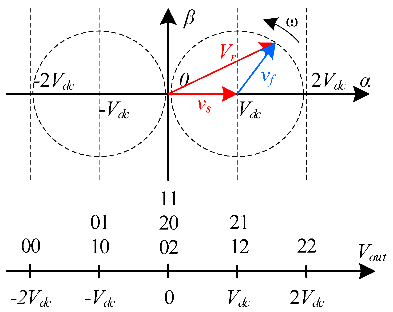
Consider the structure of a power converter consisting of cell_1 and cell_2 as shown in Figure 2. Table 1 introduces the control region of 2-cells corresponding to the output voltage. The output phase voltage is the contribution of the two-cell voltage. The active region of each cell is shown in Figure 3. The XY state vector means that cell_1 has state X and cell_2 has state Y. There are some redundancy vectors in the control that are still shown in Figure 3. For example, to achieve the state Vout = Vdc, vector 21 or 12 can be used.
Apply the strategy by using the two nearest vectors in the space vector modulation technique for the power converter, as shown in Figure 2 and Figure 3. The system includes cell_1 and cell_2. This technique generates a reference voltage (Vr) by using the two nearest state vectors in the control region. For example, if Vr is −1.6 Vdc, the proposed algorithm uses state vectors {00–01} or {00–10} as the transition sequence because if Vr is represented in the control region, it is located at a position between these state vectors. The reference vector is created by linearly combining the two nearest state vectors of the control region. Based on correction studies, the proposed algorithm is shown from Equations (1)–(4). Operator floor(x) rounds the elements of x to the nearest integers towards minus infinity [43,52].
The reference voltage of the DC/AC converter has the form that is shown in Equation (1).
where ω is angular frequency, and A is peak amplitude of the reference voltage.
For the multilevel modulation technique, the modulation voltage can be an integer of the input voltage Vdc of each cell, as shown in Equation (2).
Then, the switching vector has Equation (3):
The switching time corresponding to the switching vector is determined by Equation (4).
After determining the switching vector and the corresponding switching time, the processor sends switching signals to the cells based on the predefined cell positions.
3. Proposed Decentralized SVPWM Control Method
As introduced in Section 1, the central controller will have to perform calculations with a very large amount of computation and control a lot of IGBT switches. The central controller must perform the tasks of balancing capacitor voltage, balancing voltage between of cells, controlling load current, and controlling the voltage stability, among others. In addition, while the power converters are operating, if the system needs to be reconfigured (when a cell is damaged, add or remove cells to optimize in operation), the system needs to stop working, re-calibrate the control program, and adjust new connections based on the number of remaining cells. This process can take a relatively long time. If the number of cells in the system increases significantly, in some cases the system cannot be calibrated. To solve this problem, the decentralized control method for power converter using the space vector modulation algorithm is an appropriate choice.
As described in Section 2, the switching vector and switching time of each cell are determined based on information about the reference voltage amplitude, reference voltage frequency, and the cell’s position in the system.
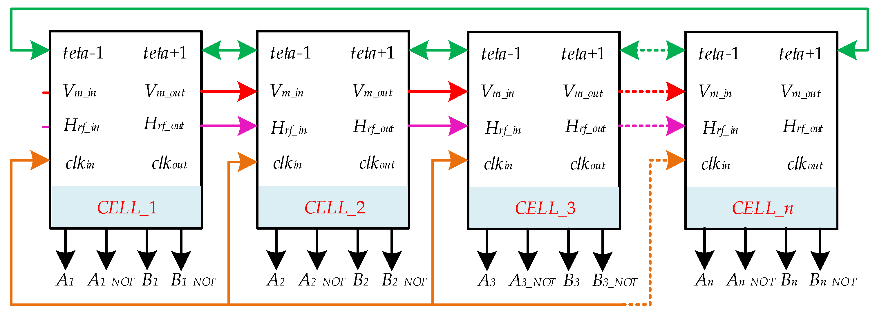
There have been many publications using different communication methods in the research direction of decentralized power converters in the form of cells that exchange limited information with neighboring cells. Cells can exchange their own phase angle with two neighboring cells in the carrier phase shift method. Cells can exchange information about the carrier amplitude magnitude in the carrier level shift method. Cells can exchange sequence numbers so that the cell’s position in the system can be determined. Each method has different advantages, in which the method of exchanging phase angle information of the module with two neighboring cells is very suitable in the design of decentralized converters. In this paper, the study uses the results of the phase shift process to quickly determine the position of the cell in a single-phase power converter. The control connection diagram between cells is shown in Figure 4.
To determine the cell’s position in the system, an algorithm for finding the individual phase angle of each cell is proposed, as in Equation (5) [30]:
where n is index of cell_n, and k is the time instant index.
For the algorithm to be able to locate cells, the phase angle (teta) needs to converge in every implementation. To ensure the algorithm can be executed, it is suggested that the initial phase angle for cells is 180 degrees, and the phase angle of the first cell (master cell) is always 0 degrees.
The total cells in single-phase is determined as shown in Equation (6):
The position of the cell in single-phase is determined as shown in Equation (7):
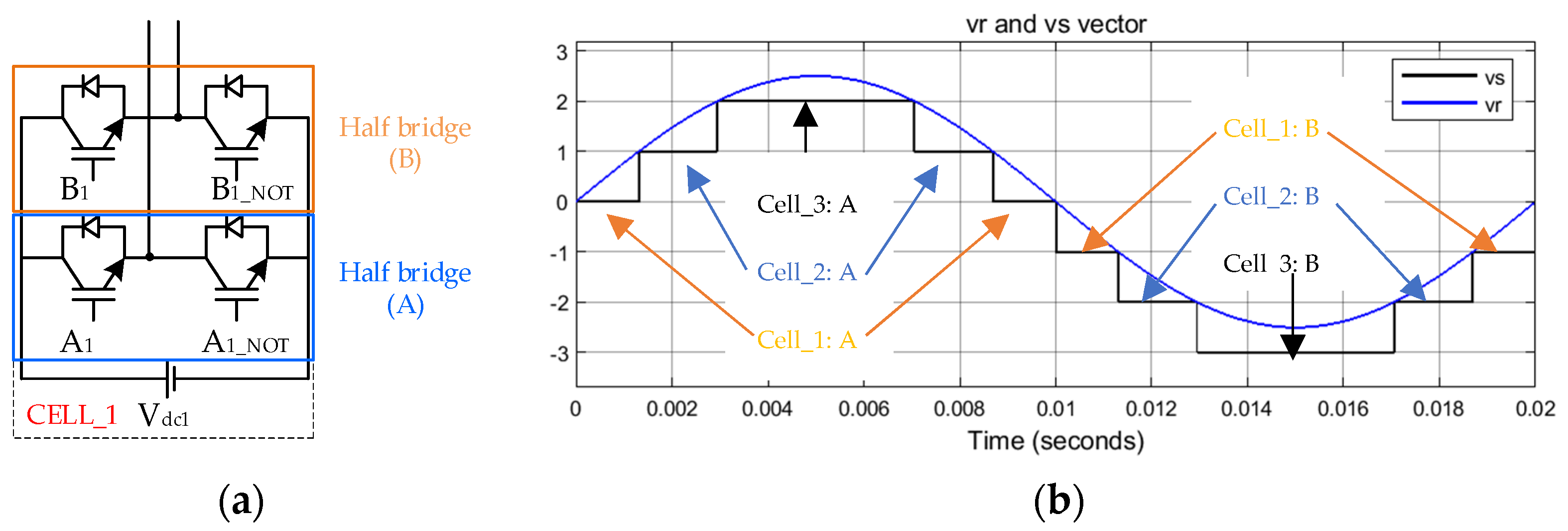
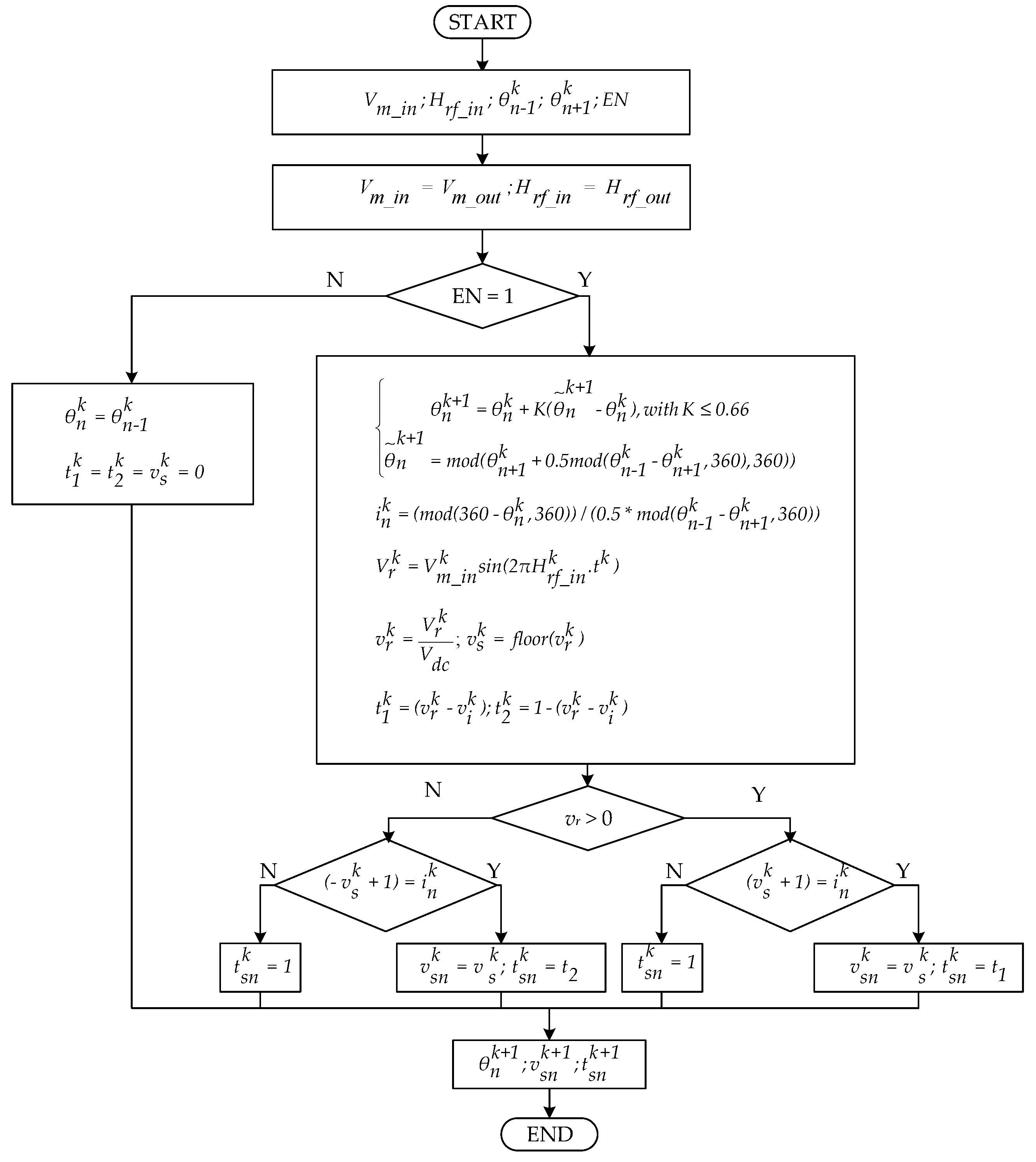
All cells operate independently of each other, requiring each cell to choose its own switching vector and appropriate switching time. This algorithm is implemented in Equations (8) and (9). To explain this algorithm, an illustrative example of 7-levels reference voltage is shown in Figure 5 (the reference voltage has an amplitude of 250 V and a frequency of 50 Hz; the power converter has input voltage of 100 V).
Figure 5 shows the division of a cell into two half bridges and vr and vi vector when the reference voltage has seven levels. If vr > 0, the switching vectors will affect the half bridge (A) of the cells (Figure 5a). The switching vector of a cell is determined, as shown in Equation (8):
If vr < 0, the switching vectors will affect the half bridge (B) of the cells (Figure 5a). The switching vector of a cell is determined, as shown in Equation (9):
Figure 6 shows the space vector modulation algorithm diagram for each cell.
During operation, the system is capable of dynamic reconfiguration, this is done by adding or removing cells as needed. In the structure shown in Figure 2, the maximum of modulation voltage will depend on the number of active cells. Thus, information about the total number of active cells is essential information for the cells, especially the master cell.
The decentralized control structures for the power converter, information about the reference voltage amplitude, and the reference frequency can be provided by one of the cells in the system. In the structure shown in Figure 4, cell_1 is chosen as the master cell. Cell_1 is responsible for generating modulated signals of the reference voltage and frequency, and synchronous clock, and then transmitting, in turn, through all cells in the system including itself. For other cells, based on the information received, combining with the synchronous clock will automatically regenerate the reference voltage signal as Equation (1) for space vector modulation. In addition, if a cell has to be removed from the converter, i.e., deactivated, the bypassing of a cell is realized using an enable bit (EN).
4. Simulation Result
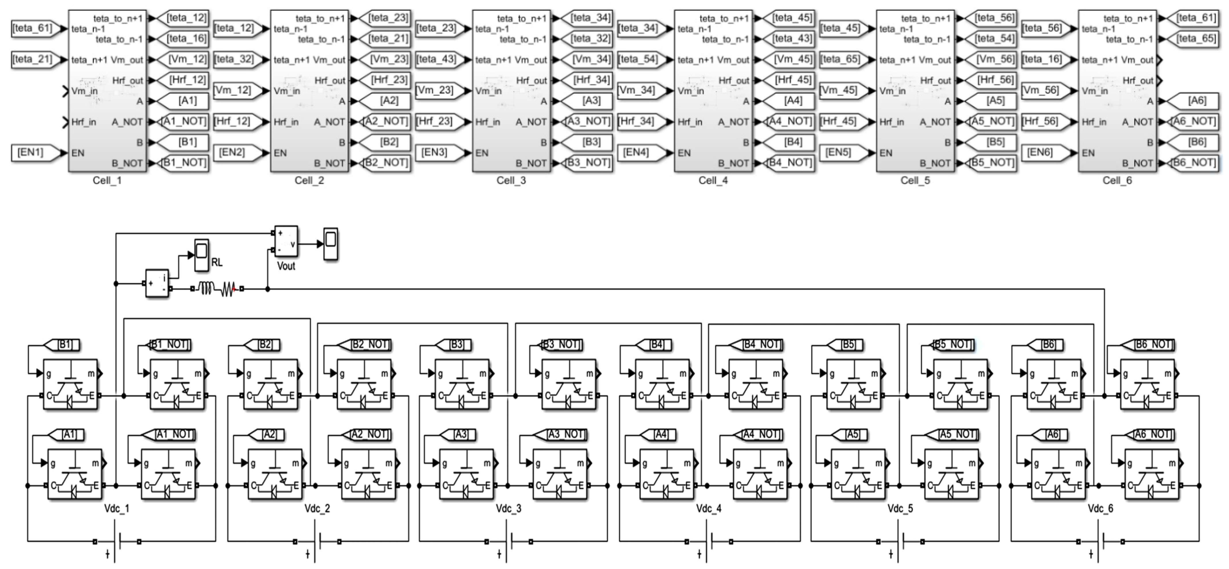
A thirteen-level single-phase power converter model is built on MATLAB/Simulink, without losing the generality of the proposed algorithm. The model consists of six cells connected in a series to perform DC/AC modulation. Figure 7 shows a simulation diagram of a decentralized 13-levels single phase power converter on MATLAB/Simulink. The output voltage will have 13 levels if all six cells are activated. The input and output functions of the signal pins of each cell are shown in Table 2; the simulation parameters of the power converter are given in Table 3;
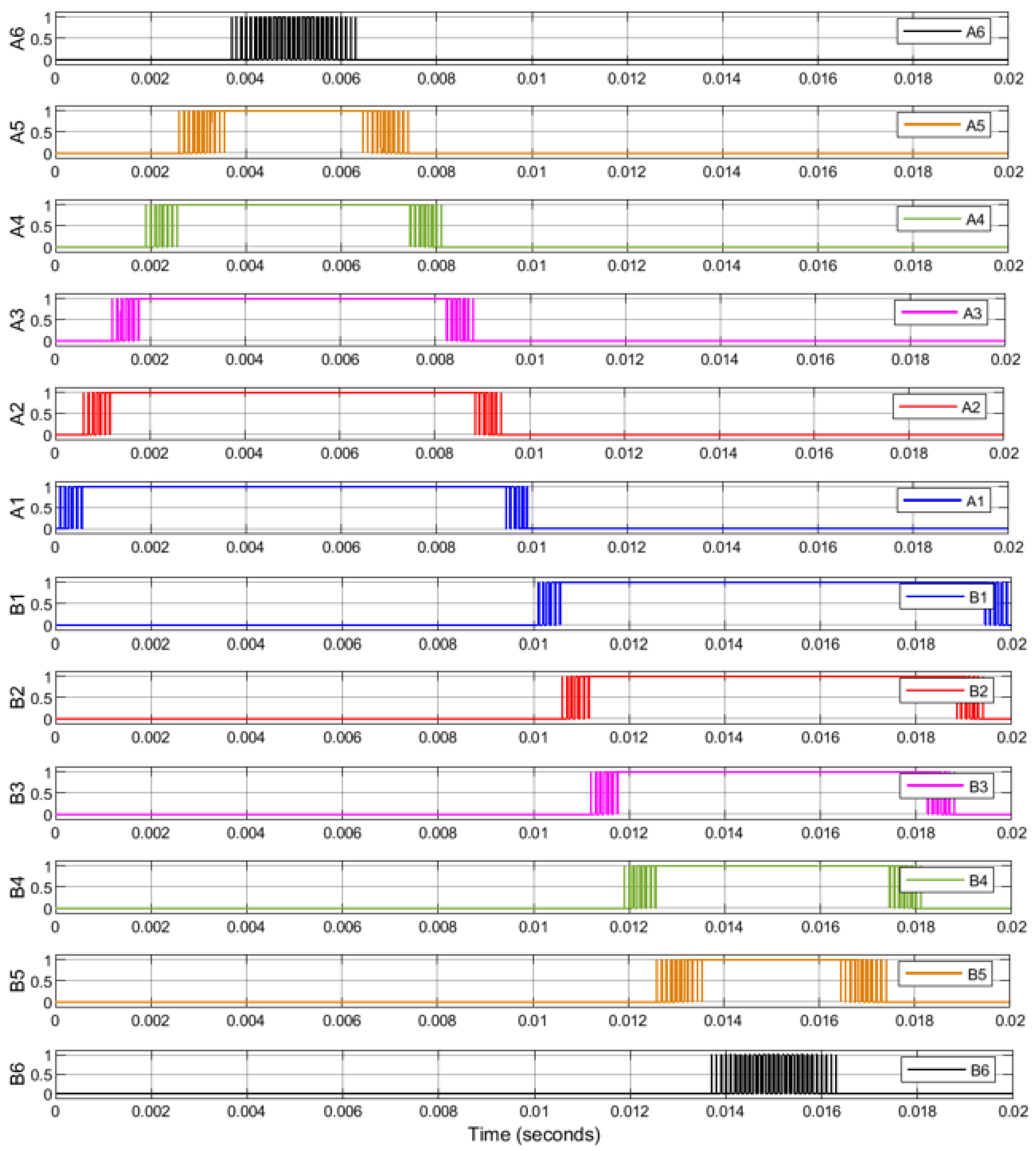
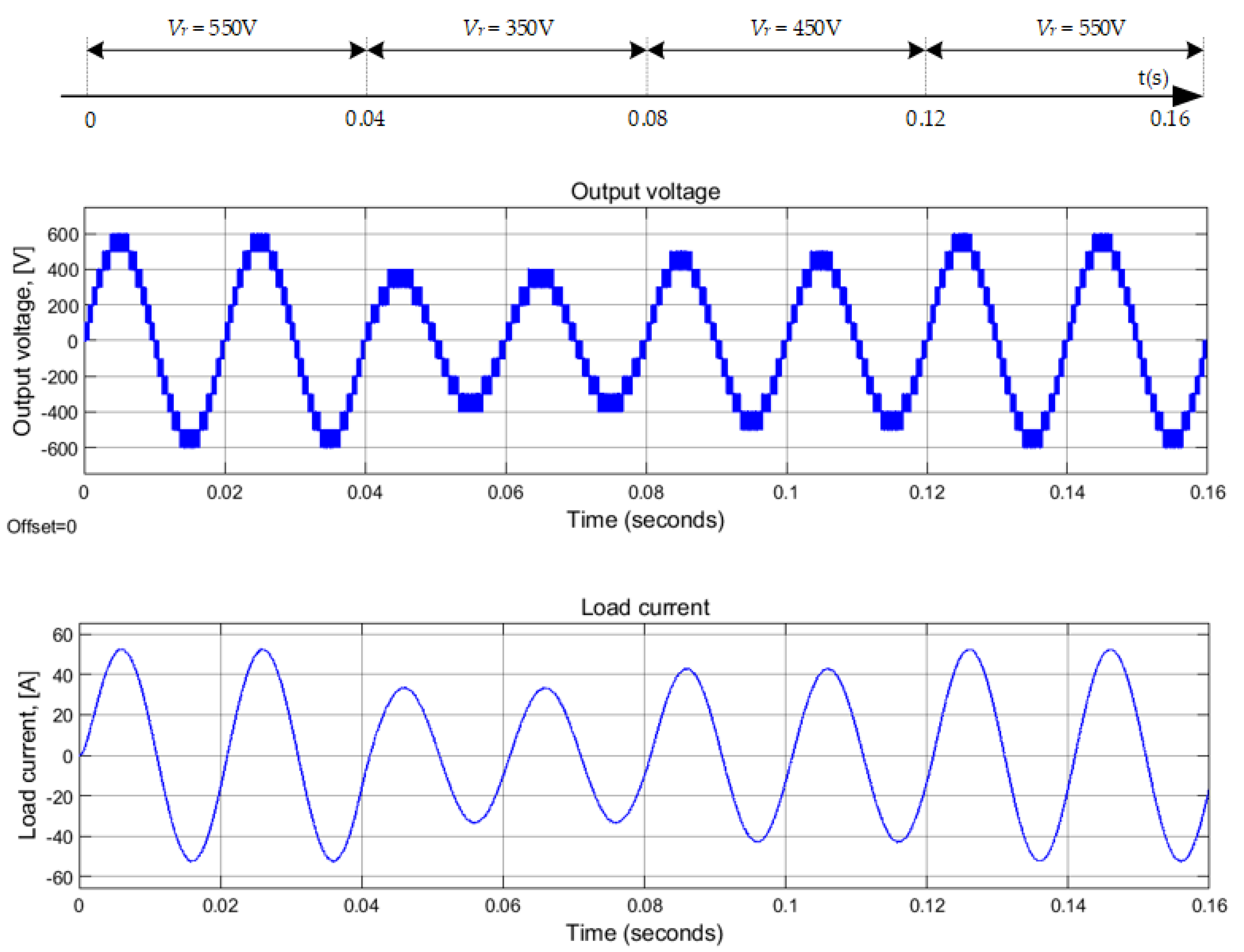
Figure 8 shows the IGBT switching signal of the six cells to create an output voltage of 13 levels. The evaluation of the amplitude response of the output voltage according to the reference voltage is shown in Figure 9. During the simulation, the reference frequency is fixed at 50 Hz. At the time of start-up, the reference voltage is set to 550 V; the output voltage has 13 levels; and the output voltage is the contribution of voltage of six cells. At 0.02 s, the reference peak voltage is adjusted to 350 V; the output voltage has nine levels; and the output voltage is the contribution of voltage of the cell_1, 2, 3, and 4. At 0.04 s, the reference voltage is 450 V, this voltage is the contribution of voltage of the cell_1, 2, 3, 4, 5, and the output voltage has 11 levels. Finally, at 0.06 s, the reference voltage is reset to 550 V, which is the same repeatable voltage as at system startup. The simulation results show that the output voltage of the single-phase inverter responds well to the required voltage amplitude.
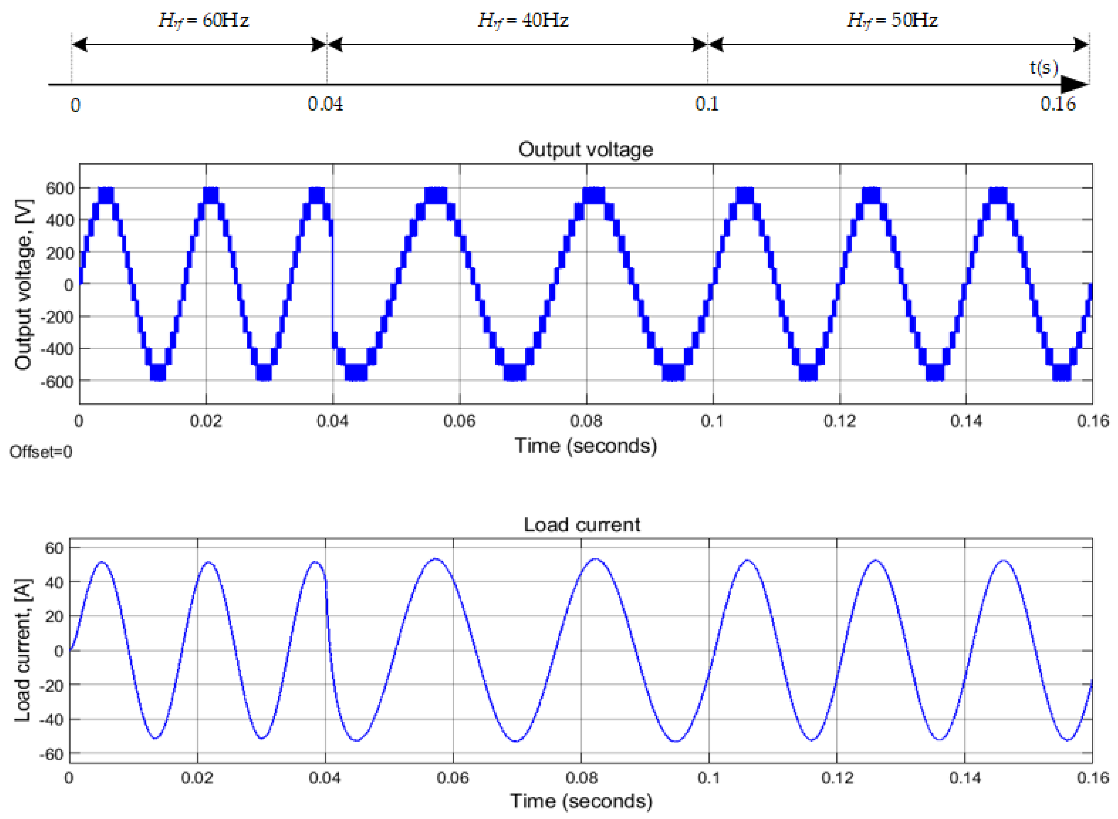
The evaluation of the frequency response according to the modulation frequency is shown in Figure 10. During the simulation, the peak voltage is fixed at 550 V. At the time of startup, the reference frequency is set to 60 Hz. At time 0.04 s, the frequency is set to 40 Hz. Finally, at time 0.1 s, the reference frequency is set to 50 Hz. During operation, when changing the modulation frequency, the output voltage waveform has 13 levels, and the voltage difference between the two stable levels is 100 V. The simulation results show the output voltage meets the required frequency.
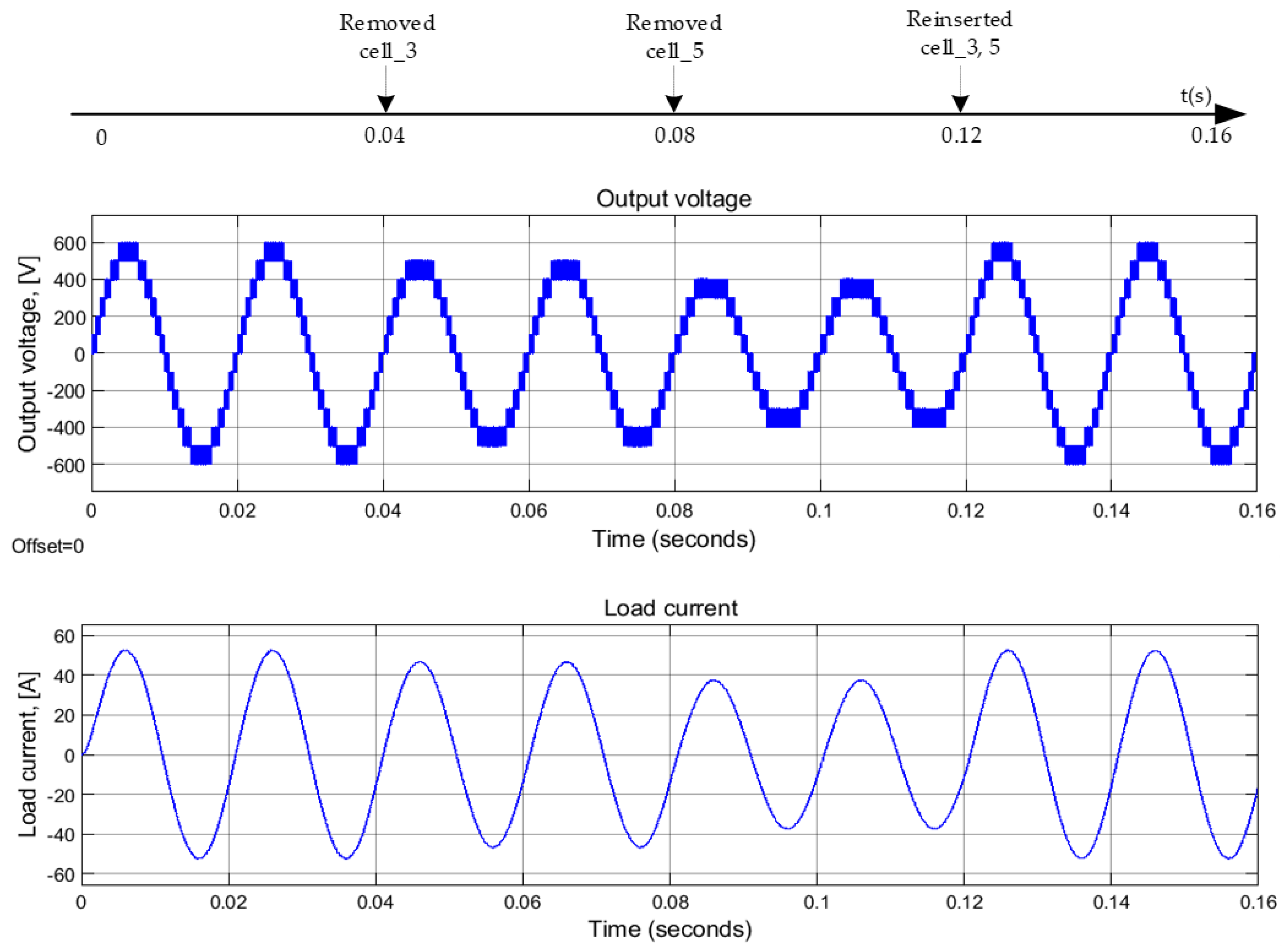
In terms of decentralized connection and the control of multilevel single-phase power converters, power converters using the SVPWM approach have the advantage of dynamic reconfiguration because of the number of cells that can be inactivated or reactivated. Figure 11 shows the simulation results of the output voltage and load current in the different reconfiguration stages. During the evaluation, the reference voltage is 550 V, and the reference frequency is 50 Hz. However, the maximum output voltage that the power converter can be modulated to depends on the number of active cells. This process is started with all six active cells, the output voltage has the contribution of all six cells, reaching 13 levels. At 0.02 s, cell_3 is removed, the system has five cells left, the maximum voltage that can be reached is 500 V, and the output voltage has 11 levels. At 0.04 s, cell_5 is removed, the system has four cells left, the output voltage has nine levels. At 0.06 s, cell_3 and cell_5 are reinserted again, the system restores to the original state with six cells, and the output voltage has 13 levels. The simulation shows that if the system needs to be dynamically reconfigured, the output voltage can be completely satisfied. During dynamic reconfiguration, depending on the characteristics and nature of the load, the reference voltage may reach the maximum limit of the modulation method (based on the number of active cells).
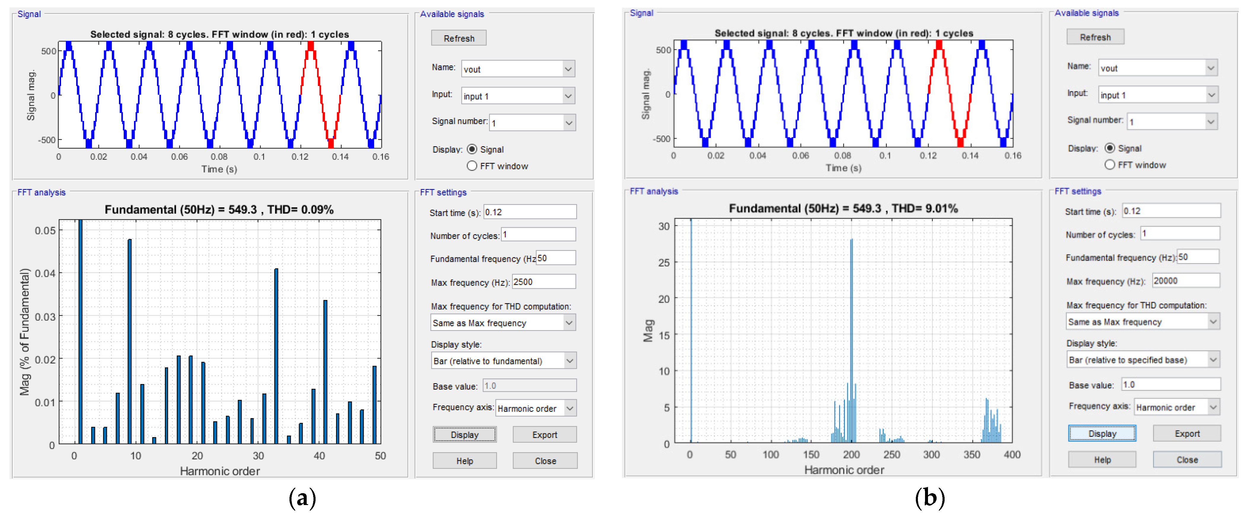
Figure 12 shows the Fast Fourier Transform (FFT) analysis for the output voltage using DSVPWM. The power converter has a reference voltage of 550 V and a reference frequency of 50 Hz. Figure 12a shows the voltage FFT spectrum within the frequency range of 0 to 450 Hz, and Figure 12b shows the voltage FFT spectrum within the range of 0 to 20 kHz. The voltage’s sinusoidal distortion is at 9.01% in the frequency range of 0 to 20 kHz and the output voltage has good quality which meets the grid connection requirements well.
5. Experimental Result
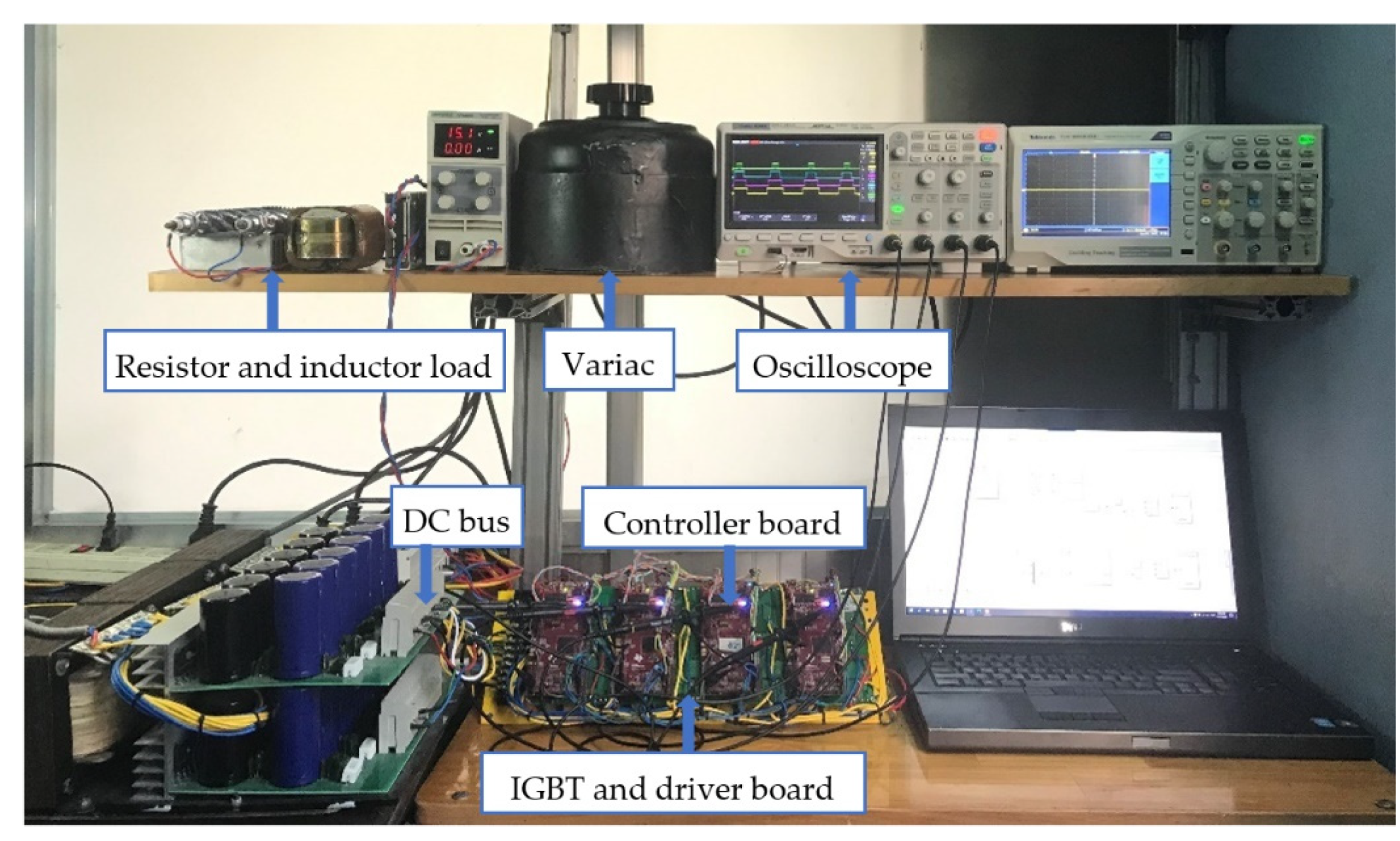
An experimental model is built to evaluate the validity and accuracy of the proposed algorithm. Without losing the generality of the proposed structure, which is the limitation of experimental devices, the experimental model built consists of four cells, and each cell uses a Digital signal processing (DSP) controller, driver and IGBT power cell. The experimental prototype is shown in Figure 13. Figure 14 shows the top and bottom faces of a cell. The dynamic circuit structure is built as shown in Figure 2, the connection between the cells is show in Figure 15, and the function of the signal pins used by the DSP is given in Table 4. DSP was developed by Texas Instruments Incorporated (TI). In order to support users of the rapid programming tool, TI has integrated the Code Composer Studio (CCS) compiler into the MATLAB/Simulink software. This experimental program is made by building a control algorithm model on MATLAB/Simulink, then using the built-in compiler to compile and load C code to the DSP board. Information on experimental components is given in Table 5. The parameters of the single-phase power converter with algorithm DSVPWM are shown in Table 6.
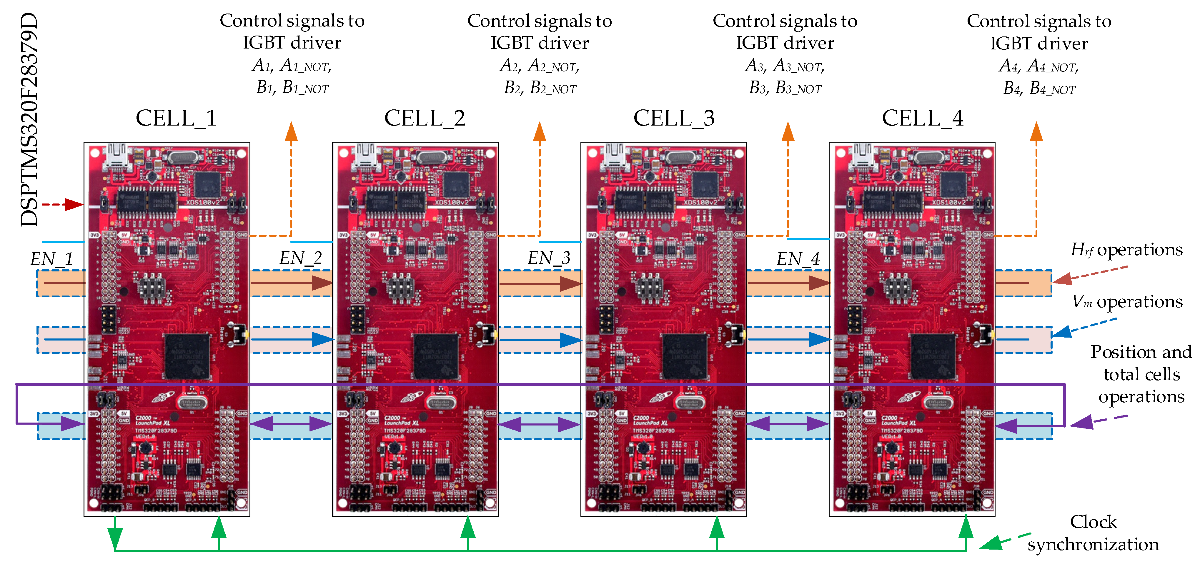
The cells of the single-phase power converter exchange information about the phase angle with neighboring cells through the asynchronous serial communication interface protocol (SCI-SCIA and SCIB). In this structure, cell_1 is called the master cell. Cell_1 will transmit reference voltage amplitude signal through cells_2, 3, and 4 by using a synchronous serial communication interface (Serial Peripheral Interface—SPI); SPIA is the master (GPIO 58, 60, 61) and SPIB is the slave (GPIO 64, 65, 66). In these cells, SPIA will transmit the amplitude of reference voltage to the next cell, and SPIB will receive the amplitude of the reference voltage from the previous cell. In addition, cell_1 also transmits the reference frequency through cell_2, 3, and 4 by using a synchronous serial communication interface. In a cell, SCID (GPIO 104, 105) will transmit the reference frequency to the next cell, and SCIC (56, 139) will receive the reference frequency from the previous cell.
Let the decentralized power converters be active, in order to synchronize the PWM signal of the cells. A synchronous clock generated from the GPIO pin 06 of the master cell (cell_1) is transmitted to GPIO pin 14 of all remaining cells, including itself; in order to synchronize the voltage reference signal, a synchronous clock generated from GPIO pin 04 of master cell is transmitted to GPIO pin 15 of all remaining cells, including itself.
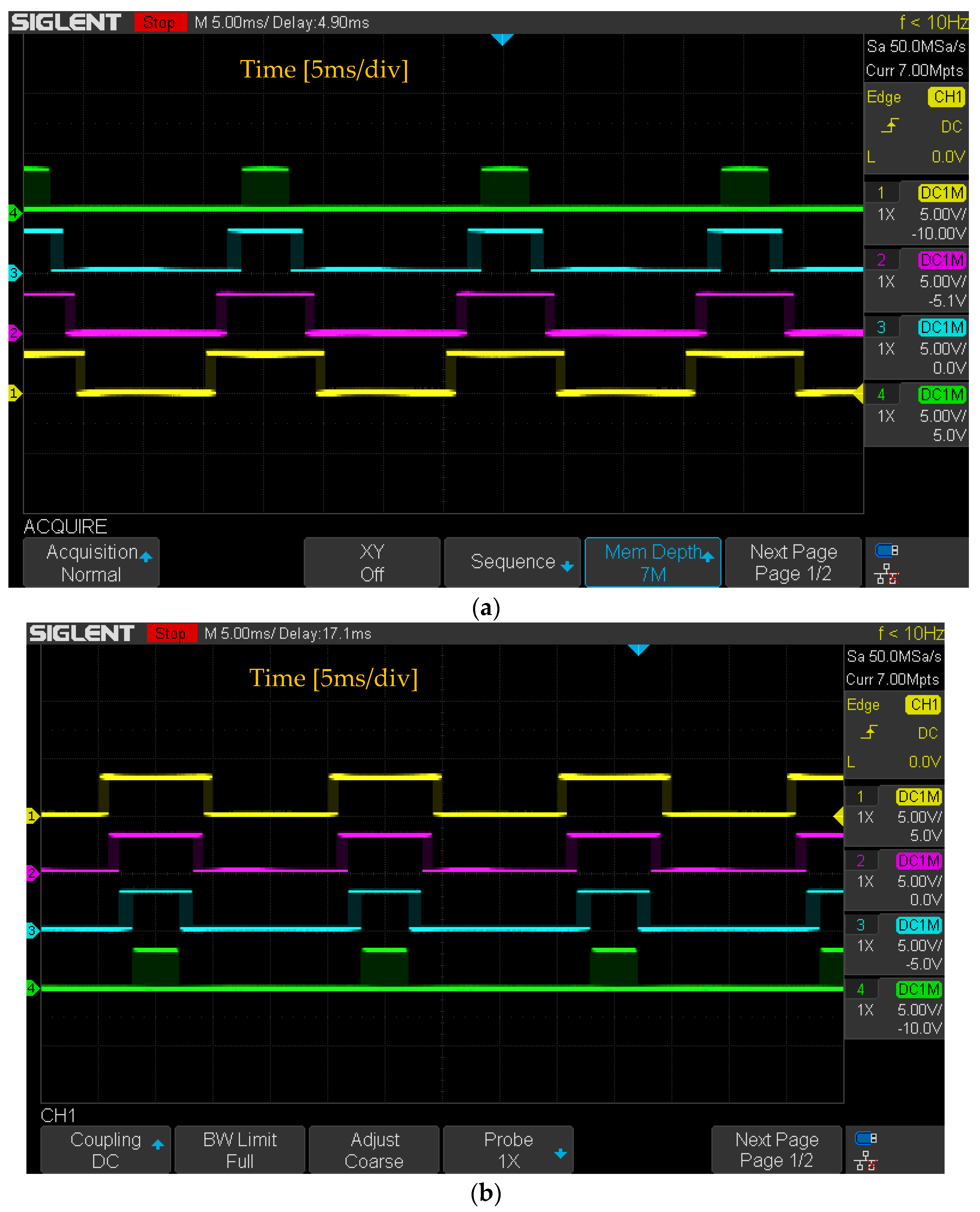
Figure 16 shows the PWM signals when all cells are active. Figure 16a depicts the PWM signal form for IGBTs in the half bridge A of cells, and Figure 16b depicts the PWM control signal for IGBTs in the half bridge B of cells. The results observed on the oscilloscope show that the PWM signals of the cells operate synchronously, exactly according to the frequency of the modulated AC voltage, and respond exactly to the four-cell nine-level converter.
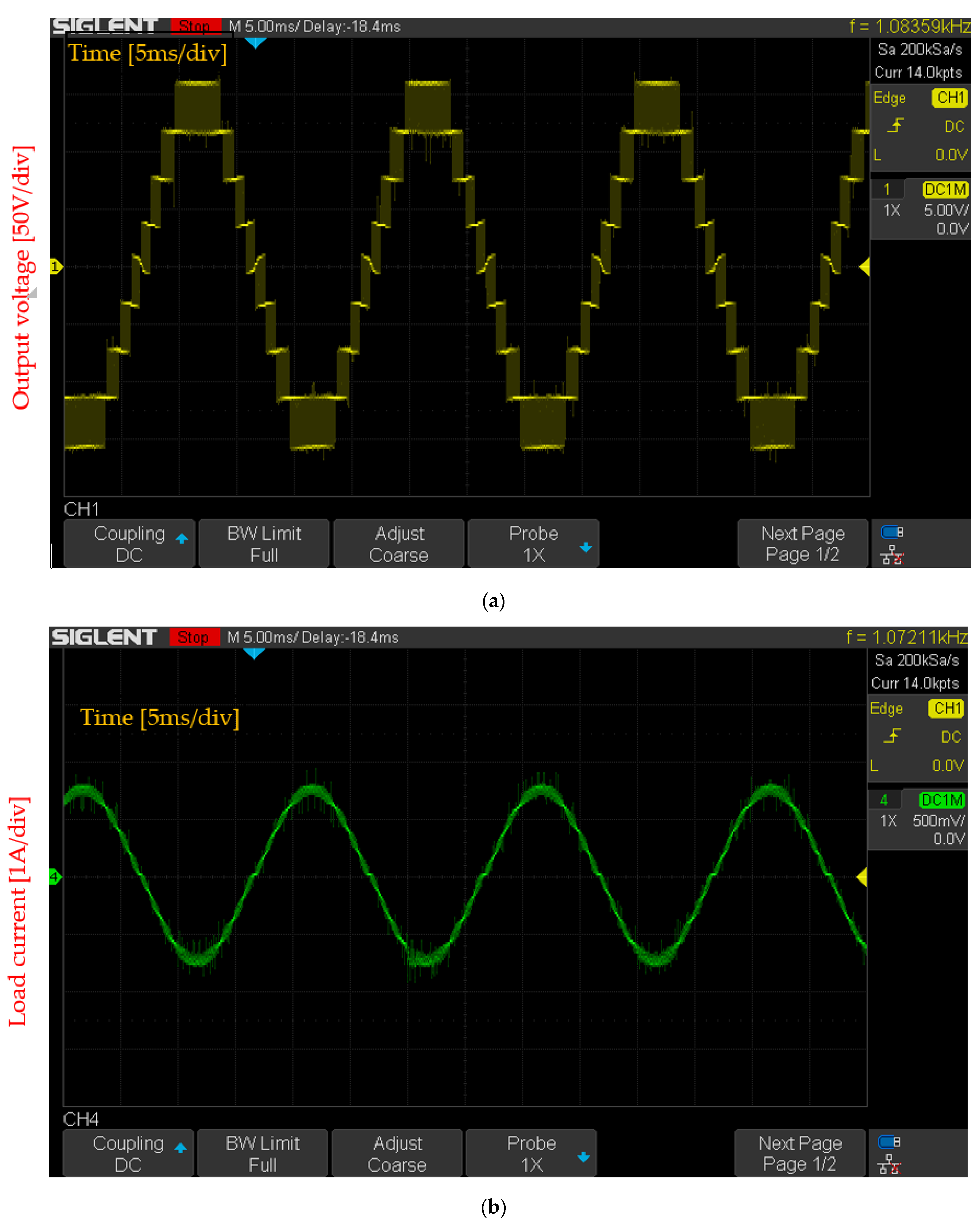
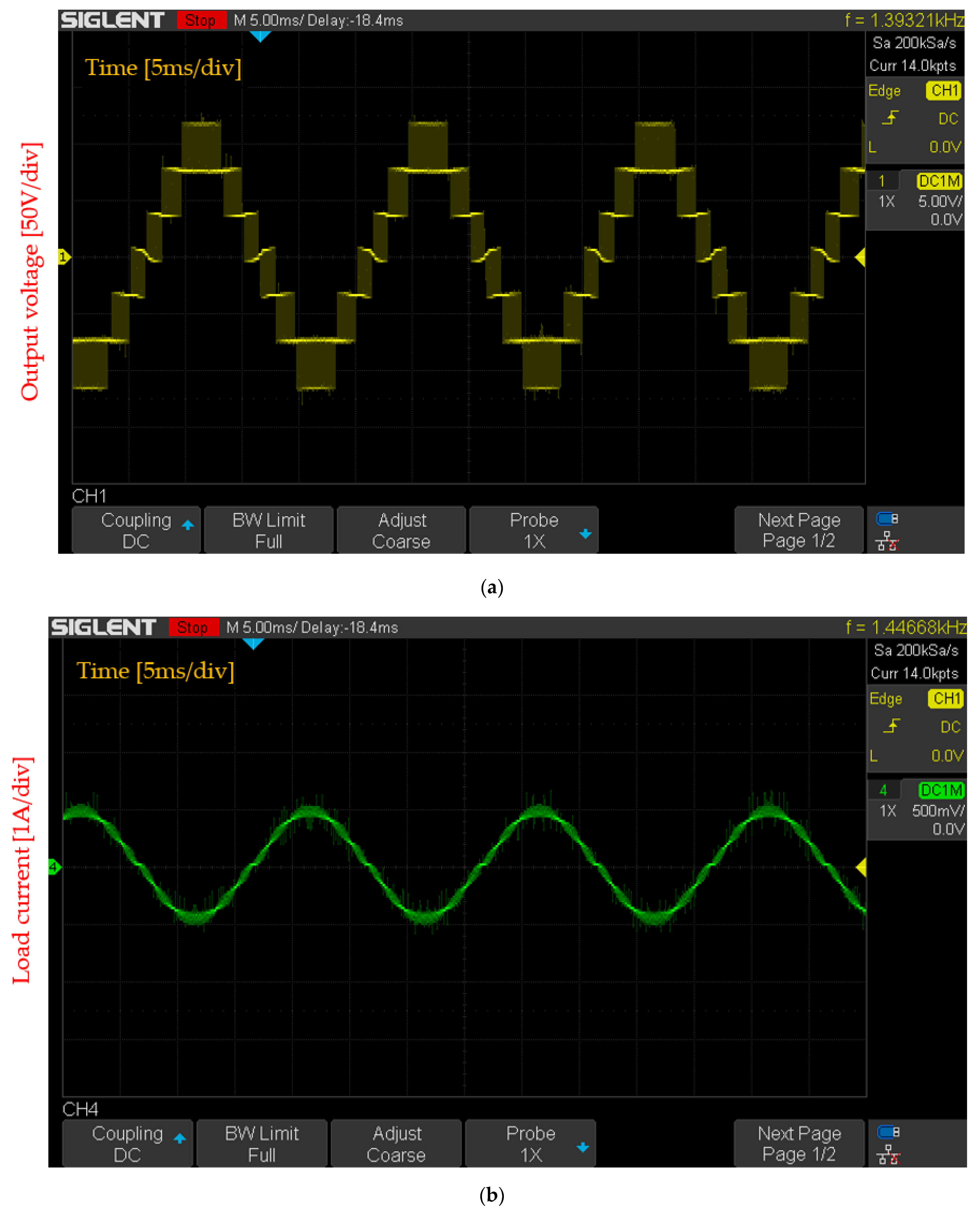
Figure 17 shows the waveform of the output voltage (Figure 17a) and load current (Figure 17b) when the all four cells of the power converter are operating, and the output voltage has nine levels. Figure 18 shows the waveform of output voltage (Figure 18a) and load current (Figure 18b) when the power converter has three active cells, and the output voltage has seven levels.
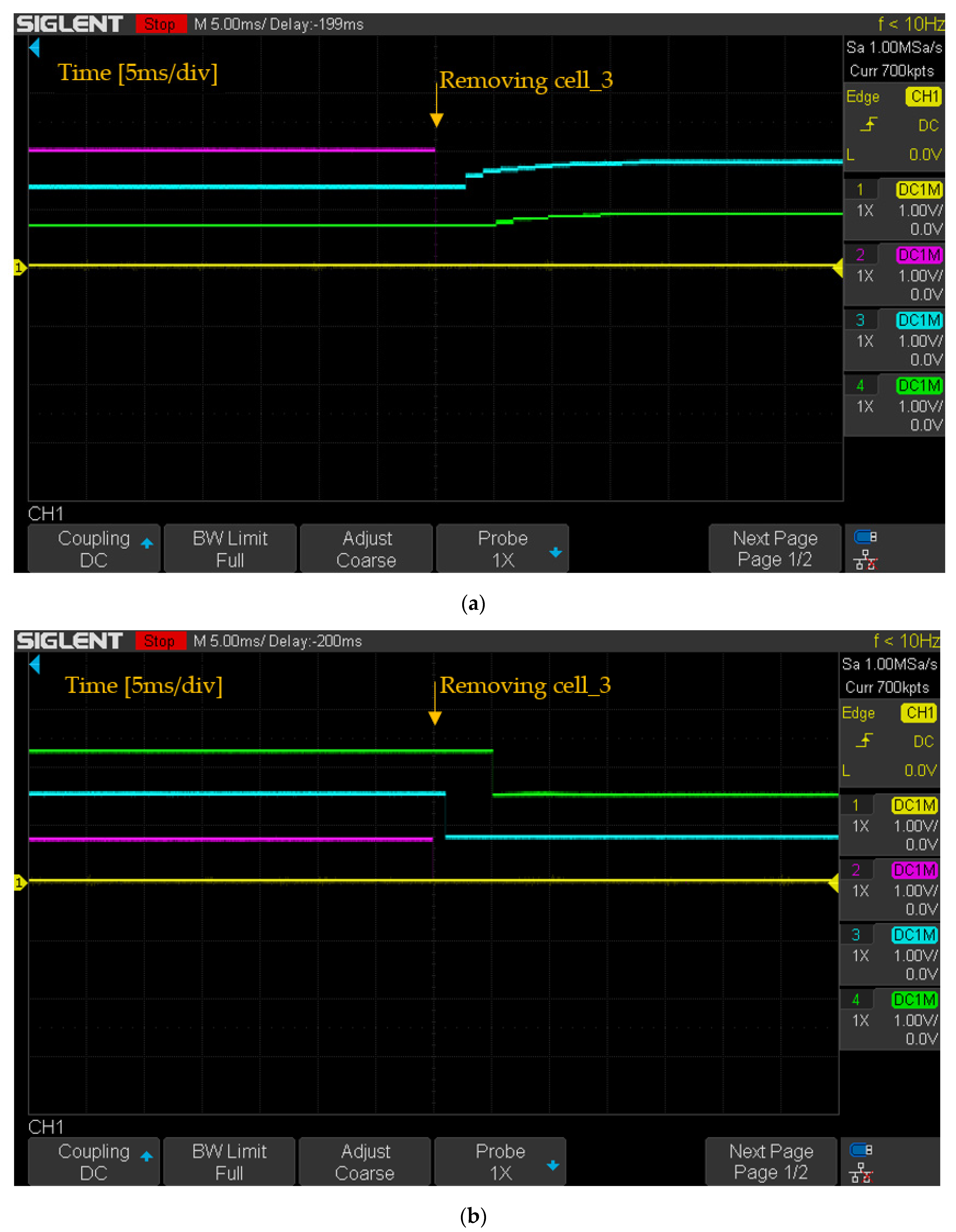
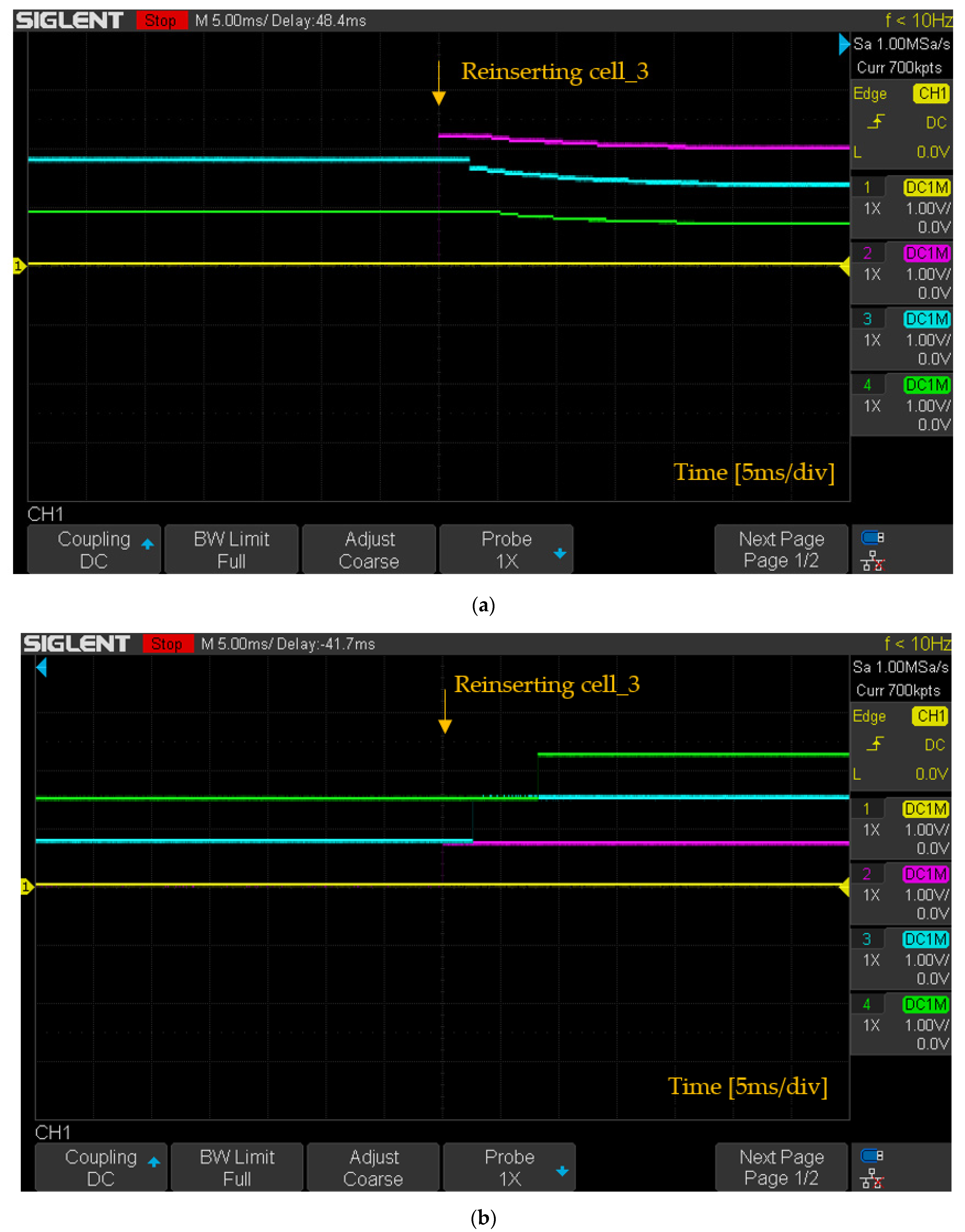
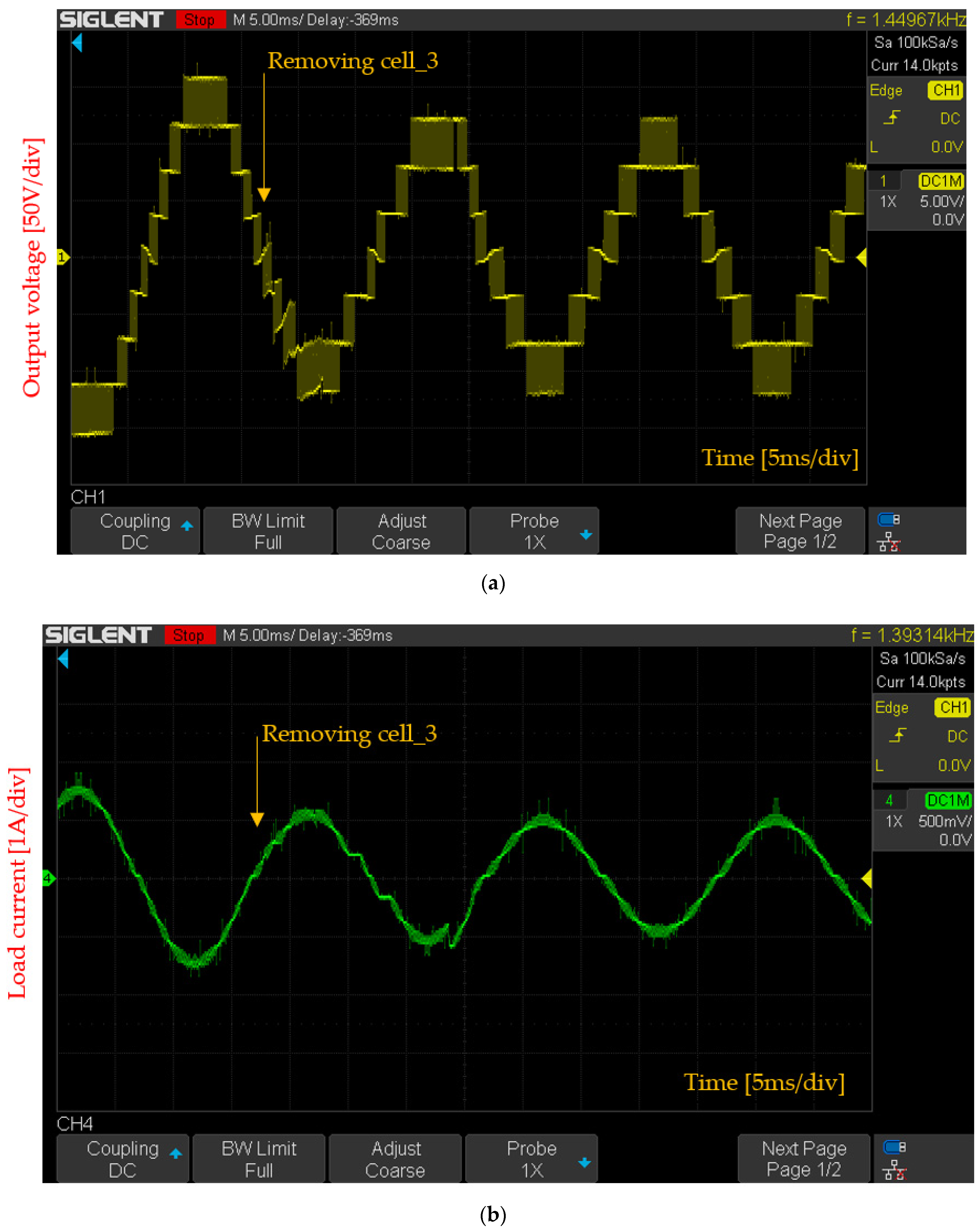
Figure 19, Figure 20 and Figure 21 depict the response of the phase angle, position of cells, output voltage, and load current when performing dynamic reconfiguration. When cell_3 is removed, the phase angle takes about 15 ms to re-stabilize, as shown in Figure 19a. Figure 19b shows the process of repositioning the cells when cell_3 is removed, and the system takes about 5 ms for the sorting process to complete. A similar experimental result when cell_3 is reinserted occurs; the phase angle of the cells takes about 15 ms to interleave evenly in 360 degrees, and the position of cells in the power converter takes about 8 ms to realign desired location. Figure 21 shows the waveform of the output voltage and load current when cell_3 is removed, the power converter has three cells left, and the voltage reaches a new equilibrium with seven levels.
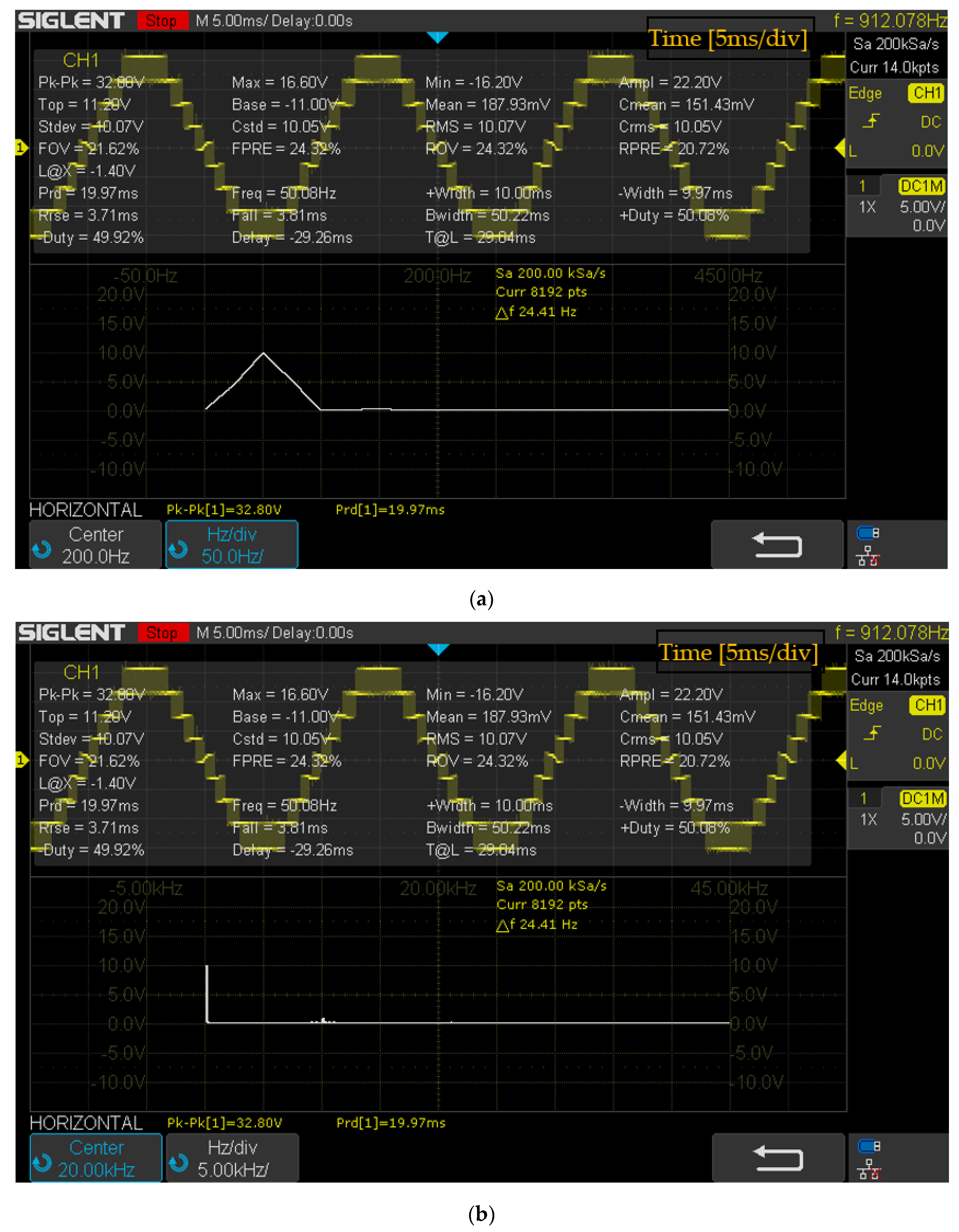
The output voltage of the nine-level single-phase power converter is analyzed by FFT on the oscilloscope; the results are presented in Figure 22. The reference frequency is 50 Hz, in order to evaluate the first harmonic, and as such the output voltage is analyzed with the FFT spectrum in the frequency range of 0 to 450 Hz, as shown in Figure 22a. In addition, to evaluate the output voltage at the switching frequency of 10 kHz, Figure 22b presents FFT analysis of the output voltage in the frequency range of 0 to 45 kHz. The results show that the output voltage has an effective amplitude of 100.7 V, the period of the output voltage is 19.97 ms, and the output voltage frequency is 50.08 Hz. The difference between the output voltage and the reference voltage is 4.4 V, which is equivalent to 4.15%, and the frequency difference between the output voltage and the reference frequency is 0.08 Hz, which is equivalent to 0.16%. The harmonics at the 10 kHz spectrum have an effective value of 10.4 V. The FFT analysis results show that the output voltage has low harmonic distortion.
6. Conclusions
In this paper, a decentralized control method for multilevel single-phase power converters has been introduced. The study applied the space vector modulation method for the decentralized power converter. The decentralized controlled power converter uses a topology that cells only exchange phase angle information with two neighboring cells, and very little information is exchanged, allowing for structural simplification. The results of this paper show that the number of communication connections and program algorithms have been significantly improved compared with previously published research [11]. The study uses the phase angle self-interleaving algorithm to determine the number cells in the system and the location of each cell, which allows the system to operate with at least three cells. The improved DSVPWM method gave a good response to the proposed structure.
The control algorithm for cells shows that the program is quite simple, which allows for lower cell microprocessors. Evaluation based on simulation results and the experimental model shows that the modulation voltage responds well to the reference signal, with very low sinusoidal distortion. In addition, dynamic reconfiguration has also been demonstrated, which is an advantage of decentralized power converters. The proposed structure and algorithm show that decentralized control power converters using SVPWM can be automatically reconfigured when adding or removing one or more cells.
Author Contributions
Conceptualization, P.C.N. and Q.D.P., methodology, P.C.N. and Q.D.P., software, experiment, P.C.N., validation, Q.D.P. and D.T.N., formal analysis and investigation, P.C.N. and Q.D.P., writing—original draft preparation, P.C.N., writing—review and editing, Q.D.P. and D.T.N. All authors have read and agreed to the published version of the manuscript.
Funding
This research received no external funding.
Institutional Review Board Statement
Not applicable.
Informed Consent Statement
Not applicable.
Data Availability Statement
Data sharing not applicable.
Acknowledgments
We acknowledge the support of time and facilities from Ho Chi Minh City University of Technology (HCMUT), VNU-HCM for this study.
Conflicts of Interest
The authors declare no conflict of interest.
References
- Kouro, S.; Malinowski, M.; Gopakumar, K.; Pou, J.; Franquelo, L.G.; Wu, B.; Rodriguez, J.; Perez, M.A.; Leon, J.I. Recent advances and industrial applications of multilevel converters. IEEE Trans. Ind. Electron. 2010, 57, 2553–2580. [Google Scholar] [CrossRef]
- Martinez-Rodrigo, F.; Ramirez, D.; Rey-Boue, A.B.; De Pablo, S.; Herrero-De Lucas, L.C. Modular multilevel converters: Control and applications. Energies 2017, 10, 1709. [Google Scholar] [CrossRef] [Green Version]
- López, O.; Dujic, D.; Jones, M.; Freijedo, F.D.; Doval-Gandoy, J.; Levi, E. Multidimensional two-level multiphase space vector PWM algorithm and its comparison with multifrequency space vector PWM method. IEEE Trans. Ind. Electron. 2011, 58, 465–475. [Google Scholar] [CrossRef]
- Biju, K.; Ramchand, R. A New Space Vector Pulse Width Modulation Technique for Single-Phase Seven-Level Inverter with Reduced Number of Switches. IETE J. Res. 2019, 1–14. [Google Scholar] [CrossRef]
- Afjeh, M.G.; Babaei, M.; Bidgoli, M.A.; Ahmarinejad, A. Deadbeat Control of a Modified Single-Phase Five-Level Photovoltaic Inverter with Reduced Number of Switches. Int. J. Photoenergy 2020, 2020, 1–16. [Google Scholar] [CrossRef]
- Jacob, J.; Chitra, A.; Thomas, R.V.; Rakesh, E. Hardware realization and analysis of a seven level reduced switch inverter with space vector modulation technique. In Proceedings of the 2017 2nd IEEE International Conference on Electrical, Computer and Communication Technologies, ICECCT 2017, Tamil Nadu, India, 22–24 February 2017. [Google Scholar] [CrossRef]
- Jafri, K.; Chen, B.C.; Chen, Y.; You, S.Z. Direct current control and experiment of a novel 9-level modular multilevel converter. IET Conf. Publ. 2012, 2012, 14031211. [Google Scholar] [CrossRef]
- Wang, Z.; Lin, H.; Ma, Y. Improved capacitor voltage balancing control for multimode operation of modular multilevel converter with integrated battery energy storage system. IET Power Electron. 2019, 12, 2751–2760. [Google Scholar] [CrossRef]
- López, Ó.; Álvarez, J.; Doval-Gandoy, J.; Freijedo, F.; Nogueiras, A.; Peñalver, C.M. Multilevel multiphase space vector PWM algorithm applied to three-phase converters. IECON Proc. 2008, 55, 3290–3295. [Google Scholar] [CrossRef]
- Prats, M.Á.M.; Franquelo, L.G.; Portillo, R.; León, J.I.; Galván, E.; Carrasco, J.M. A 3-D space vector modulation generalized algorithm for multilevel converters. IEEE Power Electron. Lett. 2003, 1, 110–114. [Google Scholar] [CrossRef]
- Cong Nguyen, P.; Dung Phan, Q. The Development of Decentralized Space Vector PWM Method for Multilevel Multiphase Converters. In Proceedings of the ICCE 2020 IEEE 8th International Conference on Communications and Electronics, Phu Quoc Island, Vietnam, 13–15 January 2021; pp. 163–168. [Google Scholar] [CrossRef]
- Dung Phan, Q.; Nguyen, P.C.; To, H.P.; Nguyen, B.A.; Le-Nguyen, D.K.; Nguyen-Huu, K.M.; Pham, L.N. Decentralized Capacitor Voltage Control of Flying Capacitor Multilevel Inverter. In Proceedings of the 2021 International Symposium on Electrical and Electronics Engineering, ISEE 2021, Seoul, Korea, 19–21 February 2021; pp. 238–243. [Google Scholar] [CrossRef]
- Phan, Q.D.; Gateau, G.; Cousineau, M.; Veit, L.; De Milly, R.; Mannes-Hillesheim, M. Ultra-fast decentralized self-aligned carrier principle for multiphase/multilevel converters. In Proceedings of the IEEE International Conference on Industrial Technology, Buenos Aires, Argentina, 26–28 February 2020; pp. 517–522. [Google Scholar] [CrossRef]
- Phan, Q.D.; Gateau, G.; Nguyen, P.C.; Cousineau, M.; To, H.P.; Nguyen, B.A.; Veit, L.; De Milly, R.; Hillesheim, M.M. A fast, decentralized, self-aligned carrier method for multicellular converters. Appl. Sci. 2021, 11, 137. [Google Scholar] [CrossRef]
- Phan, Q.D.; Gateau, G.; Nguyen, M.T.; Cousineau, M.; Thi Ngoc, T.P. Decentralized Interleaving and Current Control for Multicellular Serial-Parallel Converters. In Proceedings of the 2019 International Symposium on Electrical and Electronics Engineering, ISEE 2019, Ho Chi Minh City, Vietnam, 10–12 October 2019; pp. 199–204. [Google Scholar] [CrossRef]
- Huang, J.; Wu, T.; Wang, K. Modular multi-level converter control method based on CPS—PWM. In Proceedings of the 2017 International Conference on Computer Systems, Electronics and Control, ICCSEC 2017, Dalian, China, 25–27 December 2017; pp. 1528–1531. [Google Scholar] [CrossRef]
- Du, S.; Dekka, A.; Wu, B.; Zargari, N. Classical Control of Modular Multilevel Converter. Modul. Multilevel Convert. Anal. Control. Appl. 2018, 79–102. [Google Scholar] [CrossRef]
- Nguyen, M.H.; Kwak, S.; Kim, T. Phase-Shifted Carrier Pulse-Width Modulation Algorithm with Improved Dynamic Performance for Modular Multilevel Converters. IEEE Access 2019, 7, 170949–170960. [Google Scholar] [CrossRef]
- Wang, K.; Deng, Y.; Peng, H.; Chen, G.; Li, G.; He, X. An improved CPS-PWM scheme-based voltage balancing strategy for MMC with fundamental frequency sorting algorithm. IEEE Trans. Ind. Electron. 2019, 66, 2387–2397. [Google Scholar] [CrossRef]
- Zhang, Y.; Adam, G.P.; Lim, T.C.; Finney, S.J.; Williams, B.W. Analysis of modular multilevel converter capacitor voltage balancing based on phase voltage redundant states. IET Power Electron. 2012, 5, 726–738. [Google Scholar] [CrossRef]
- Wang, K.; Deng, Y.; Li, W.; Peng, H.; Chen, G.; He, X. Fundamental frequency sorting strategy for capacitor voltage balance of modular multilevel converters with phase disposition PWM. In Proceedings of the IEEE Applied Power Electronics Conference and Exposition—APEC, Long Beach, CA, USA, 20–24 May 2016; pp. 1450–1455. [Google Scholar] [CrossRef]
- Gao, C.; Liu, X.; Liu, J.; Guo, Y.; Chen, Z. Multilevel converter with capacitor voltage actively balanced using reduced number of voltage sensors for high power applications. IET Power Electron. 2016, 9, 1462–1473. [Google Scholar] [CrossRef]
- Sasongko, F.; Akagi, H. Low-Switching-Frequency Operation of a Modular Multilevel DSCC Converter with Phase-Shifted Rotating-Carrier PWM. IEEE Trans. Power Electron. 2017, 32, 5058–5069. [Google Scholar] [CrossRef]
- Dekka, A.; Wu, B.; Zargari, N.R.; Fuentes, R.L. A Space-Vector PWM-Based Voltage-Balancing Approach with Reduced Current Sensors for Modular Multilevel Converter. IEEE Trans. Ind. Electron. 2016, 63, 2734–2745. [Google Scholar] [CrossRef]
- Yongchao, C.; Yanda, L.; Ling, Z. A novel SVPWM Algorithm Considering Neutral-Point Potential Balancing for Three-Level NPC Inverter. Electronics 2016, 20, 69–75. [Google Scholar] [CrossRef] [Green Version]
- Mekhilef, S.; Khudhur, H.I.; Belkamel, H. DC link capacitor voltage balancing in three level neutral point clamped inverter. In Proceedings of the 2012 IEEE 13th Workshop on Control and Modeling for Power Electronics, COMPEL 2012, Kyoto, Japan, 10–13 June 2012. [Google Scholar] [CrossRef] [Green Version]
- Zhang, X.; Wang, N.; Lin, H.; Yin, T.; Zhang, Z.; Shu, Z. An optimal control algorithm of capacitor voltage balancing for modular multilevel converter. In Proceedings of the IEEE Applied Power Electronics Conference and Exposition—APEC, Anaheim, CA, USA, 17–21 March 2019; pp. 3504–3507. [Google Scholar] [CrossRef]
- Palanisamy, R.; Shanmugasundaram, V.; Vidyasagar, S.; Kalyanasundaram, V.; Vijayakumar, K. A SVPWM Control Strategy for Capacitor Voltage Balancing of Flying Capacitor Based 4-Level NPC Inverter. J. Electr. Eng. Technol. 2020, 15, 2639–2649. [Google Scholar] [CrossRef]
- Phan, Q.D.; Gateau, G.; Nguyen, M.T.; Cousineau, M. 2D Decentralized Interleaving Principle for Multicell Serial-Parallel Converters. In Proceedings of the International Conference on Power Electronics and Drive Systems, Toulouse, France, 9–12 July 2019. [Google Scholar] [CrossRef]
- Gateau, G.; Dung, P.Q.; Cousineau, M.; Do, P.U.T.; Le, H.N. Digital implementation of decentralized control for multilevel converter. In Proceedings of the 2017 International Conference on System Science and Engineering, ICSSE 2017, Ho Chi Minh City, Vietnam, 21–23 July 2017; pp. 558–562. [Google Scholar] [CrossRef]
- Gateau, G.; Cousineau, M.; Mannes-Hillesheim, M.; Dung, P.Q. Digital decentralized current control for parallel multiphase converter. In Proceedings of the IEEE International Conference on Industrial Technology, Melbourne, Australia, 13–15 February 2019; pp. 1761–1766. [Google Scholar] [CrossRef]
- Liu, J.; Yao, W.; Lu, Z.; Du, L.; Ji, Y. A distributed control structure and synchronization method for complex converter based on CAN. In Proceedings of the 2017 IEEE Southern Power Electronics Conference, SPEC, Puerto Varas, Chile, 4–7 December 2017; pp. 1–6. [Google Scholar] [CrossRef]
- Xu, B.; Tu, H.; Du, Y.; Yu, H.; Liang, H.; Lukic, S. A Distributed Control Architecture for Cascaded H-Bridge Converter with Integrated Battery Energy Storage. IEEE Trans. Ind. Appl. 2021, 57, 845–856. [Google Scholar] [CrossRef]
- Rong, Y.; Wang, J.; Shen, Z.; Burgos, R.; Boroyevich, D.; Zhou, S. Distributed Control and Communication System for PEBB-based Modular Power Converters. In Proceedings of the 2019 IEEE Electric Ship Technologies Symposium, ESTS 2019, Washington, DC, USA, 14–16 August 2019; pp. 627–633. [Google Scholar] [CrossRef]
- Xia, B.; Li, Y.; Li, Z.; Konstantinou, G.; Xu, F.; Gao, F.; Wang, P. Decentralized Control Method for Modular Multilevel Converters. IEEE Trans. Power Electron. 2019, 34, 5117–5130. [Google Scholar] [CrossRef]
- Dutta, S.; Mallik, R.; Majmunovic, B.; Mukherjee, S.; Seo, G.S.; Maksimovic, D.; Johnson, B. Decentralized Carrier Interleaving in Cascaded Multilevel DC-AC Converters. In Proceedings of the 2019 IEEE 20th Workshop on Control and Modeling for Power Electronics, COMPEL 2019, Toronto, ON, Canada, 17–20 June 2019; pp. 1–6. [Google Scholar] [CrossRef]
- Sinha, M.; Poon, J.; Johnson, B.B.; Rodriguez, M.; Dhople, S.V. Decentralized Interleaving of Parallel-connected Buck Converters. IEEE Trans. Power Electron. 2019, 34, 4993–5006. [Google Scholar] [CrossRef]
- He, Y.; Liu, Y.; Lei, C.; Cheng, R.; Liu, J. CBPWM and SVPWM equivalent relationship on single-phase NPC N-level inverters with arbitrary sequence. IET Power Electron. 2020, 13, 3975–3986. [Google Scholar] [CrossRef]
- Du, S.; Wu, B.; Zargari, N.R.; Cheng, Z. A Flying-Capacitor Modular Multilevel Converter for Medium-Voltage Motor Drive. IEEE Trans. Power Electron. 2017, 32, 2081–2089. [Google Scholar] [CrossRef]
- Celikovic, J.; Das, R.; Le, H.P.; Maksimovic, D. Modeling of Capacitor Voltage Imbalance in Flying Capacitor Multilevel DC-DC Converters. In Proceedings of the 2019 IEEE 20th Workshop on Control and Modeling for Power Electronics, COMPEL 2019, Toronto, ON, Canada, 17–20 June 2019; pp. 1–8. [Google Scholar] [CrossRef]
- Da Silva Carvalho, S.; Halamíček, M.; Vukadinović, N.; Prodić, A. Digital PWM for Multi-Level Flying Capacitor Converters with Improved Output Resolution and Flying Capacitor Voltage Controller Stability. In Proceedings of the 2018 IEEE 19th Workshop on Control and Modeling for Power Electronics, COMPEL 2018, Padova, Italy, 25–28 June 2018. [Google Scholar] [CrossRef]
- Lei, Y.; Liu, W.C.; Pilawa-Podgurski, R.C.N. An analytical method to evaluate flying capacitor multilevel converters and hybrid switched-capacitor converters for large voltage conversion ratios. In Proceedings of the 2015 IEEE 16th Workshop on Control and Modeling for Power Electronics, COMPEL 2015, Vancouver, BC, USA, 12–15 July 2015. [Google Scholar] [CrossRef]
- Diao, F.; Wu, X.; Xiong, C.; Feng, X. A simplified SVPWM strategy for universal single-phase multilevel converter. In Proceedings of the 2016 IEEE 8th International Power Electronics and Motion Control Conference, IPEMC-ECCE Asia 2016, Hefei, China, 22–26 May 2016; pp. 43–46. [Google Scholar] [CrossRef]
- Sneha, K.; Das, B.M. A low switching frequency based 17 level inverter with nearest level control. In Proceedings of the 9th IEEE International Conference on Power Electronics, Drives and Energy Systems, PEDES 2020, Jaipur, India, 16–19 December 2020. [Google Scholar]
- Liu, Q.; Chen, A.; Du, C.; Zhang, C. A modified nearest-level modulation method for modular multilevel converter with fewer sub-modules. In Proceedings of the 2017 Chinese Automation Congress, CAC 2017, Jinan, China, 20–22 October 2017; pp. 6551–6556. [Google Scholar]
- Park, Y.H.; Kim, D.H.; Kim, J.H.; Han, B.M. A new scheme for nearest level control with average switching frequency reduction for modular multilevel converters. J. Power Electron. 2016, 16, 522–531. [Google Scholar] [CrossRef] [Green Version]
- Bute, P.R.; Mittal, S.K. Simulation Study of Cascade H-bridge Multilevel Inverter 7-Level Inverter by SHE Technique. In Proceedings of the 4th International Conference on Computing Methodologies and Communication, ICCMC 2020, Erode, India, 11–13 March 2020; pp. 670–674. [Google Scholar]
- Nguyen, M.H.; Kwak, S. Nearest-Level Control Method with Improved Output Quality for Modular Multilevel Converters. IEEE Access 2020, 8, 110237–110250. [Google Scholar] [CrossRef]
- Dhayalini, K.; Vinothini, N. Design of multilevel inverter using Nearest Level Control Technique with reduced power switches. In Proceedings of the 4th International Conference on Electrical Energy Systems, ICEES 2018, Chennai, India, 7–9 February 2018; pp. 568–571. [Google Scholar]
- Setti, M.; Ouassaid, M.; Cherkaoui, M. New power efficient seven-level inverter topology controlled by flexible nearest level modulation. In Proceedings of the 2017 International Conference on Electrical and Information Technologies, ICEIT 2017, Rabat, Morocco, 15–18 November 2017; pp. 1–6. [Google Scholar]
- Sarwar, M.I.; Sarwar, A.; Farooqui, S.A.; Tariq, M.; Fahad, M.; Beig, A.R.; Alamri, B. A Hybrid Nearest Level Combined with PWM Control Strategy: Analysis and Implementation on Cascaded H-Bridge Multilevel Inverter and its Fault Tolerant Topology. IEEE Access 2021, 9, 44266–44282. [Google Scholar] [CrossRef]
- Leon, J.I.; Vazquez, S.; Watson, A.J.; Franquelo, L.G.; Wheeler, P.W.; Carrasco, J.M. Feed-forward space vector modulation for single-phase multilevel cascaded converters with any DC voltage ratio. IEEE Trans. Ind. Electron. 2009, 56, 315–325. [Google Scholar] [CrossRef]
- Leon, J.I.; Portillo, R.; Franquelo, L.G.; Vazquez, S.; Carrasco, J.M.; Dominguez, E. New space vector modulation technique for single-phase multilevel converters. IEEE Int. Symp. Ind. Electron. 2007, 617–622. [Google Scholar] [CrossRef] [Green Version]
- Zhang, J. Research on Control Method of Single-Phase Inverter Power Based on SVPWM. In Proceedings of the 2015 International Conference on Intelligent Systems Research and Mechatronics Engineering, Zhengzhou, China, 11–13 April 2015; pp. 942–945. [Google Scholar] [CrossRef] [Green Version]
- Zhang, Z.; Xie, Y.X.; Huang, W.P.; Le, J.Y.; Chen, L. A new SVPWM method for single-phase three-level NPC inverter and the control method of neutral point voltage balance. In Proceedings of the 12th International Conference on Electrical Machines and Systems, ICEMS 2009, Tokyo, Japan, 15–18 November 2009; pp. 3–6. [Google Scholar] [CrossRef]
Figure 1.
Flying capacitor converters.

Figure 2.
Full bridge multilevel power converters.

Figure 3.
Principle of simplified SVPWM for five-level single-phase converter.

Figure 4.
Communication between cells in the system.

Figure 5.
vr and vi vector when the reference voltage has seven levels. (a) the division of a cell into two half bridges; (b) vr and vi vector.
Figure 5.
vr and vi vector when the reference voltage has seven levels. (a) the division of a cell into two half bridges; (b) vr and vi vector.

Figure 6.
Algorithm flowchart of one cell.

Figure 7.
Simulation model of a 13-level single-phase inverter.

Figure 8.
Chain of switching impulse at the IGBT pins of phase a in one cycle.

Figure 9.
Waveform of output voltage and load current when change the modulation voltage.

Figure 10.
Waveform of output voltage and load current when the modulation frequency is changed.

Figure 11.
Waveform of output voltage and load current in a case of reconfiguration.

Figure 12.
Analysis of THD output voltage of DSVPWM. (a) the voltage FFT spectrum within the range of 0 to 450 Hz; (b) the voltage FFT spectrum within the range of 0 to 20 kHz.
Figure 12.
Analysis of THD output voltage of DSVPWM. (a) the voltage FFT spectrum within the range of 0 to 450 Hz; (b) the voltage FFT spectrum within the range of 0 to 20 kHz.

Figure 13.
Experimental prototype for the test of the DSVPWM methods.

Figure 14.
Top and bottom faces of a cell.

Figure 15.
Communication between cells in the system for the experimentation.

Figure 16.
Experimental results of PWM control signals, (a) An; (b) Bn.

Figure 17.
Experimental result of 9-level single-phase power converter, (a) output voltage; (b) load current.
Figure 17.
Experimental result of 9-level single-phase power converter, (a) output voltage; (b) load current.

Figure 18.
Experimental result of 7-level single-phase power converter, (a) output voltage; (b) load current.
Figure 18.
Experimental result of 7-level single-phase power converter, (a) output voltage; (b) load current.

Figure 19.
The system response of reconfiguration when removing cell 3, (a) phase angle of the cells; (b) ordinal number of cells.
Figure 19.
The system response of reconfiguration when removing cell 3, (a) phase angle of the cells; (b) ordinal number of cells.

Figure 20.
The system response of reconfiguration when reinserting cell_3, (a) phase angle of the cells; (b) ordinal number of cells.
Figure 20.
The system response of reconfiguration when reinserting cell_3, (a) phase angle of the cells; (b) ordinal number of cells.

Figure 21.
Output voltage and load current when removing cell_3, (a) output voltage; (b) load current.
Figure 21.
Output voltage and load current when removing cell_3, (a) output voltage; (b) load current.

Figure 22.
FFT analysis of output voltage: (a) spectrum of nine first harmonics; (b) spectrum of 900 harmonics.
Figure 22.
FFT analysis of output voltage: (a) spectrum of nine first harmonics; (b) spectrum of 900 harmonics.


Table 1.
Output Voltage of 2-Cell Single-Phase.
| Cell_1 State | Cell_2 State | Output Voltage |
|---|---|---|
| 0 | 0 | −2 Vdc |
| 0 | 1 | −Vdc |
| 1 | 0 | −Vdc |
| 0 | 2 | 0 |
| 1 | 1 | 0 |
| 2 | 0 | 0 |
| 1 | 2 | Vdc |
| 2 | 1 | Vdc |
| 2 | 2 | 2 Vdc |
Table 2.
Input and Output of Cell Model in DSVPWM method.
| Input | Output | ||
|---|---|---|---|
| teta − 1 | Phase, index from cell n − 1 | Vm_out | Send the reference voltage amplitude to next cell |
| teta + 1 | Phase, index from cell n + 1 | Hrf_out | Send the reference voltage frequency to next cell |
| Vm_in | Get the reference voltage amplitude from previous cell | clkout | Send the synchronous clock pulse to others cell |
| Hrf_in | Get the reference voltage frequency from previous cell | A1, A1_NOT, B1, B1_NOT | The cell’s IGBT control signal. |
| clkin | Get synchronous clock pulse from master cell | ||
| EN | Enable | ||
Table 3.
Simulation Parameters.
| Parameter | Symbol | Unit | Value |
|---|---|---|---|
| Load | L | H | 0.01 |
| R | Ω | 10 | |
| Voltage source | Vdc_1 … Vdc_6 | V | 100 |
| Switching frequency | kHz | 10 | |
| Sampling time | Ts | s | 1 × 10⁻⁶ |
| Reference voltage signal | V | 550 | |
| Reference frequency signal | Hz | 50 |
Table 4.
Function of control pins of digital signal processor (DSP).
| Symbol | Pin on DSP | Parameter |
|---|---|---|
| teta | DACA | Observe the phase angle of the cell |
| in | DACB | Observe the cell’s position |
| EN | GPIO 25 | Enable |
| SPIB (GPIO 64, 65, 66) | Received the amplitude of reference voltage from previous cell | |
| SPIA (GPIO 58, 60, 61) | Transmitted the amplitude of reference voltage to next cell | |
| SCIC (GPIO 56, 139) | Received the reference frequency from the previous cell | |
| SCID (GPIO 104, 105) | Transmitted the reference frequency to the next cell | |
| SCIA (GPIO 8, 9) SCIB (GPIO 18, 19) | Transmitted and received phase angle of cell | |
| GPIO 14 | Received synchronous clock pulse PWM from master cell | |
| GPIO 15 | Received synchronous clock pulse of the reference voltage from master cell | |
| GPIO 06 | Transmitted synchronous clock pulse PWM to others cell | |
| GPIO 04 | Transmitted synchronous clock pulse of the reference voltage to others cell | |
| An | GPIO 0 | The control signal IGBT An of cell_n |
| An_NOT | GPIO 1 | The control signal IGBT An_NOT of cell_n |
| Bn | GPIO 2 | The control signal IGBT Bn of cell_n |
| Bn_NOT | GPIO 3 | The control signal IGBT Bn_NOT of cell_n |
Table 5.
Information on experimental components. Reprinted from Ref. [14].
Table 5.
Information on experimental components. Reprinted from Ref. [14].
| Component | Information |
|---|---|
| Controller board | C2000 Delfino MCUs F28379D LaunchPad Development Kit, Texas Instruments, Dallas, TX, USA |
| Power circuit | IGBT GW40N120KD |
| Driver circuit | Hybrid integrated IGBT driver MORNSUN QP12W08S-37, MORNSUN Guangzhou Science & Technology Co., Ltd, GuanDong province, China |
| Current sensor | Current Transducer LTS 15-NP I P N = 15 At-LEM Tektronix A622 AC/DC current probe |
Table 6.
Experimental parameters.
| Symbol | Parameter | Unit | Value |
|---|---|---|---|
| Z | Load resistor | Ω | 100 |
| Load inductor | H | 0.004 | |
| Vdc1…Vdc4 | Voltage source | V | 40 |
| fsw | Switching frequency | kHz | 10 |
| Ts | Sampling time | s | 5 × 10⁻⁵ |
| Vm | Reference voltage | V | 150 |
Publisher’s Note: MDPI stays neutral with regard to jurisdictional claims in published maps and institutional affiliations. |
© 2022 by the authors. Licensee MDPI, Basel, Switzerland. This article is an open access article distributed under the terms and conditions of the Creative Commons Attribution (CC BY) license (https://creativecommons.org/licenses/by/4.0/).
Share and Cite
MDPI and ACS Style
Nguyen, P.C.; Phan, Q.D.; Nguyen, D.T. A New Decentralized Space Vector PWM Method for Multilevel Single-Phase Full Bridge Converters. Energies 2022, 15, 1010. https://0-doi-org.brum.beds.ac.uk/10.3390/en15031010
AMA Style
Nguyen PC, Phan QD, Nguyen DT. A New Decentralized Space Vector PWM Method for Multilevel Single-Phase Full Bridge Converters. Energies. 2022; 15(3):1010. https://0-doi-org.brum.beds.ac.uk/10.3390/en15031010
Chicago/Turabian StyleNguyen, Phu Cong, Quoc Dung Phan, and Dinh Tuyen Nguyen. 2022. "A New Decentralized Space Vector PWM Method for Multilevel Single-Phase Full Bridge Converters" Energies 15, no. 3: 1010. https://0-doi-org.brum.beds.ac.uk/10.3390/en15031010
Note that from the first issue of 2016, this journal uses article numbers instead of page numbers. See further details here.