1. Introduction
As the need for charging electronic devices continues to increase, so does the demand for energy as a necessary component of our daily lives [
1]. Wireless power transmission (WPT) comprises different technologies for the transmission of electromagnetic (EM) energy through physical matter and objects, such as, air, water, or walls [
2]. Unlike traditional wire-based power transmission, WPT technology is not constrained by cables and does not produce electrical sparks, thus enabling high mobility charging [
3]. Furthermore, damaged or loosened copper cables present a hazard when charging devices [
4,
5]. Therefore, wireless charging autonomy is the preferred method of energy pooling over short or medium ranges for devices, such as drones, after achieving close contact with a power source [
6]. Drones or unmanned aerial vehicles (UAVs) generally operate on high-powered batteries, such as Li-po batteries, resulting in limited flight times and shorter distance deployments. The exhaustion of the power source onboard the aircraft is one of the main challenges of these systems in the fixed missions of any UAV [
7]. Equipping drones with a larger battery unit does not solve the problem as it increases the weight of the aircraft, thereby reducing the available weight for the payload, such as the coil, which is a critical element in WPT [
8].
Secondly, a UAV or drone battery must often be charged for a long time. Therefore, highly efficient battery use during flight requires direct intervention from humans or the drone must be completely independent during direct charging [
9]. However, wireless charging of the drone battery depends on the coil’s design diameter, outer and inner coil, and the number of turns to increase the transfer power efficiency and distance between the two coils. The imbalance in lateral misalignment distance between two coils while charging is a permanent electrical engineering problem that remains a challenge [
10]. Therefore, this problem has prompted the need for continuous verification because the two coils are usually not perfectly aligned due to differences in the coupling factors and the wrong hovering position of the drone. Moreover, these differences can decrease the transfer distance and power transfer efficiency of the receiving coil, causing fluctuations during the charging process [
11]. Therefore, improving the energy transfer efficiency and transfer distance in several directions is crucial to achieve energy transmission with high efficiency. Generally, to alleviate this problem, the diameter of the primary winding must be greater than the diameter of the secondary winding and equal to twice the distance between the two windings [
12], or a group of several fixed primary windings must be used to charge a single winding [
13].
Some researchers have studied the problems of limited battery life, long charging times, short distances, precision requirements when smart devices use a transmitter pad with the axial alignment distance and lateral misalignment in different directions, and low transfer power efficiency for long distances. The coil dimensions are defined correctly when the axes of the z parameters of the coupled coils coincide at an axially aligned distance perfectly [
14]. The rotation of the plane containing one coil from a pair of coupled coils without a change in the coil alignment results in planar rotation [
15]. Range variations arise from changes in the distance between a pair of coupled coils. The vertical alignment could manifest in two forms: angular or lateral misalignment. These alterations in configuration may occur individually or could appear together at varying degrees in a coupled interaction between the transmitter and the receiver coils.
Drones are expected to be the strength of smart flying as they could act as the first respondent to any emergency that may arise. However, they have a huge limitation of having very low-power densities, an inability to sustain longer flight times, and hovering in the wrong directions that cause loss of power [
16]. To optimize energy transfer performance, the misalignment transmission distance between the transmitter and receiver coils is the main limitation of magnetic resonator coupling (MRC) methods, which are sensitive to transmitting and receiving coil alignment. However, this is limited by each of the coils’ diameters (large or small), the line spacing of each coil, and the distance between the transmitter and receiver coils [
17]. Researchers have been attempting to reduce misalignment using two major approaches [
18]. The first approach is the auto-alignment of the two coils by either the movement of the transmitter or receiver coil, and the second is through electrical manipulation, such as resonance or modifying compensation topologies. Regardless, major challenges in the adoption of WPT technology still exists due to the types of power amplifiers that are available for far-field applications.
Two methods can be implemented to improve payload due to charging purposes and the misalignment challenges. First, the battery of the transmitter circuit can be automatically charged after the drone lands at the base station. However, this method is still unfeasible due to the inaccuracy of landing positions. Second, the battery of the transmitter circuit can be charged by the battery of the receiver coils of the drone by using a class E power amplifier (PA). In addition, a spiral coil platform is used for the force-sensing resistor (FSR) as an ON/OFF switch for drone landing that gives higher accuracy during battery charging of the coil receiver.
The two techniques that can be implemented for the drone charging station were considered as solutions in this paper. The first method optimizes the weight of a coil against maximum transfer efficiency and distance by testing several coils parameters in a simulation and selecting the best material such as aluminum or copper. The second method is to use an electrical connection (such as a Class E PAs) between the drone coil receiver and the transmitter station coil.
This work aims to solve the misalignment’s tolerance by simulating and designing a suitable coil for the platform station between the transmitter and receiver side at various distances. In addition, our work proposed using FSR as the first solution to know the landing position of a drone on the platform. Because a drone cannot hover in a static position and can fluctuate in angular and planar misalignment situations which cause difficulty in modelling, this study concentrated on two types of misalignments, i.e., vertical misalignment and lateral misalignment (horizontal). This is most common in drones that are used in applications such as radiation monitoring and smart agriculture. The drone is controlled remotely in a fixed straight path and air impedes diagonal movement between the wings.
This study proposes a drone charging platform based on a new WPT design and analysis method under vertical and misalignment conditions. The study considers the misalignment between the transmitter and receiver coils focusing on transfer power, efficiency, and distance. The WPT system was designed, simulated, implemented, and tested considering the suitable weight of the landed drone and by maintaining drone hovering conditions.
The design was obtained after different simulations and validated with an experimental laboratory test. The main focuses regarding WPT were the transfer coupling coefficient, quality factor, mutual inductance, transfer power, coil design, and to some extent, the transfer efficiency increases as described in [
9]. Several articles have discussed the major concerns about recharging the battery using the WPT-based misalignment coil approach [
10,
19,
20,
21], and they are highlighted in the next section.
2. Related Works
Transfer power and efficiency are common problems in designing WPT as both result in decreased system performance. Misalignment between the transmitter and receiver coils of a WPT system for charging a drone battery has posed an additional challenge, especially in transferring higher power at high efficiencies, which has limited the potential use of WPT for future applications such as in the IoT [
22]. Therefore, several studies have been directed in this area in recent years. However, the misalignment between coils in WPT still poses a challenge. Although many researchers have conducted experiments, and extensive efforts have been made on the development of near-field (NF) WPT techniques (i.e., IC and MRC) and have been presented, several practical challenges have yet to be fully resolved. These include coil orientation, air gap, transfer power, transfer efficiency, operating frequency, misalignment positions, coil weight, coil size, and electromagnetic radiation interference, especially in high frequency applications with RF components. The main advantages of all onboard components are their lightweight and compact designs.
Several researchers have reviewed alignment and misalignment conditions in terms of distances and angles and found several solutions such as the minimization of variations in the perpendicular component of the magnetic field [
10], a solution to the inverse field problem [
19], tunability of the impedance network [
21] and repressing the increase in mutual inductance [
23]. These solutions can increase transfer efficiency, power, and distance for this type of misalignment solution [
8,
14,
24].
Campi et al. [
25] designed a primary coil (copper Litz wire on the receiver and tube coils on the transmitter) to withstand severe coil misalignment conditions; the landing gear of the secondary coil with a suitably formed aluminum tube has a minimal effect on the drone’s (DJI F550 with five motors) aerodynamics, coupled with the additional weight (78 g) of the platform station. According to the results, the proposed system reduced the electrical loss and maintained good mechanical properties by assuming a different size of landing gear (e.g., the landing point height) and a frequency of 300 kHz with a maximum power of 70 W. These results demonstrated that in the design circuit, series–series topology (S–S) is better than series–parallel (S–P) according to the number of turns of the primary coil, which range from 1 to 10. They also tested several load resistances (
RL) from 1 to 20 Ω with 90% to 95% transfer efficiency between the calculated and measured misalignment ranges (from 5 to 30 cm) between the
x-axis and
y-axis. In this work, there is a small coil design on the drone and a large tube coil with a 10-turn coil on the platform station, which is a limitation of the work as the system loses more power.
Lan et al. [
26] presented a Class EF PA inverter and Class D rectifier based on a high-frequency MRC system built with lightweight copper pipe air-core coils at both ends and lightweight electronics on the receiver side. The designed WPT charging platform is circular with a 1m diameter, thus allowing for the lateral misalignment of up to 250 mm with a transfer efficiency of 70% and a frequency of 6.78 MHz. The DJI Matrice 100 quadcopter drones were supplied with 22.2 V and 4500 mAh with a Lithium-Polymer (Li-Po) battery for WPT, which was designed to charge the same battery when using wire. The designed coil (inner: 350 mm and outer: 40 mm) was built with a box (platform) with a two-turn square shape for an increased Q-factor and inductance of 1143 and 1.13 µH, respectively, with a 140 mm transfer distance capacity. The drone landed on the charging pad nine times successfully.
Yusmarnita et al. [
27] proposed a Class E PA by studying the effect of switching and performance analysis behaviors at a frequency of 1 MHz. They designed an electronic circuit (using a Proteus simulation electronic circuit) based on Class E PAs, then analyzed and compared the measured, theoretical and simulated results. The electronic circuit design consists of the resistance load network and a single transistor operated as a switch at the carrier frequency of the output signal. The simulation experiment achieved a power input and output of 9.84 and 8.62 W, respectively, with an efficiency of 87.56%. The experimental result achieved 98% transfer efficiency with 9.60 and 9.45 W power input and output values. Finally, the theoretical calculation reached 10 W of input and output power, with a transfer efficiency of 100%. The operating frequency of the proposed system was equal to 1 MHz. The switch control signal type was IRF510 MOSFET, which used a PIC16877A microcontroller, and the results indicated that the zero-voltage switching (ZVS) condition could be completed effectively.
Wang and Song, et al. [
28] presented a circuit based on Class E PAs using a ZVS oscillator. The theoretical calculation and simulation of MRC WPT system parameters were investigated. They achieved high power–delivery efficiency and low current according to an analysis of the load current waveform (0.156 A) and voltage (28.2 V). In their paper, they introduced theoretical and simulation results without the designed coil. Their calculation results showed improvement in the transfer efficiency with low current and a high voltage of 29.34 V. However, the comparison between the calculation and simulation results was inconsistent with the analyzed theoretical results.
Kang et al. [
29] proposed and analyzed the effect of the misalignment of resonators based on an MRC wireless power-charging system that used a slit ground resonator on a laptop computer with a dimension of 24.5 cm × 39 cm. The proposed system was tested in correct alignment and misalignment conditions. The design achieved good results when used in alignment conditions. However, the transfer efficiency decreased by 45% when there was a misalignment between the movable receiver and the transmitter. The tube coils were designed for the transmitter (one turn as a square) and receiver (five turns in a circlular shape), resulting in the mutual inductance of 0.905 μH at 100 mm when increasing the diameter to 600 mm for both coils. The results improved the mutual inductance and
k in lateral misalignment distance. This is useful only for charging laptops on a table when increasing the diameter of coils with a transfer efficiency of 55% at 200 mm. Note that by designing the big rectangular coil geometry, such as its width, dimension, and number of turns on the transmitter side and the circular coil on the receiver side at the center, the misalignment tolerance between a transmitter and receiver coil can be solved.
Rybicki et al. [
30] presented a prototype of an MRC system in the design of a Class E PA, which was selected due to its ability to achieve highly efficient DC–AC conversion. However, the serial to parallel (S–P) connection of resonance capacitors was intended to operate at 1 MHz at high frequency. The selection of the rectifier parameters allowed operation at a high efficiency (80%) and with a transfer distance of 7.5 cm, with a
k equal to 0.196 of RLC impedance through the simulation and analysis of the matching circuit coil design.
The WPT system suffers from reduced transmission performance during energy transmission due to the mismatch between the cores of the two coils (transmitter and receiver). Many types of alignment configuration exist between coils, such as vertical variation, planar, angular, lateral (horizontal), planar and horizontal, and angular horizontal [
31]. All alignments have different directions and applications. Thus, the basic parameters, such as mutual inductance, efficiency, and output power, vary during experiments [
32]. Rohan et al. [
33] used an intelligent automatic alignment algorithm based on the hill climb algorithm to control misaligned coupling between coils. A control unit was suggested and executed to measure the terminal voltage of each transmission coil and align the midpoint of the transmiting and receiving coil.
In most recent studies, several attempts using the multi-loop topology in impedance matching have made sure that the MRC state, even with a differing distance between the transmitting and receiving coils, reduced the variation of the input impedance [
34]. The general technique [
35] developed by Massachusetts Institute of Technology (MIT) researchers is a highly resonant magnetic WPT, which reduces the misalignment problem to a certain extent for 2 m of transfer distance. WPT is limited by three factors: (1) Efficient and long-distance power transfer; (2) The International Commission on Non-Ionizing Radiation Protection (ICNIRP) established limits on the strength, frequency, and other factors of electromagnetic radiations and fields used in wireless applications; and (3) the IEEE and ICNIRP established electromagnetic radiation limits, which may make designing a system difficult. The lateral misalignment distance depends on the efficiency and air gap of various factors, such as coil directions, alignment, frequency, and coil design between the transmitter and receiver coils of the WPT system.
This paper aims to address two problems that were not tackled in the previous studies. The first was the receiver coil’s payload minimization, which can be solved by choosing lighter materials (e.g., aluminum) and testing the coil design by simulation. The second problem is the issue of low transfer power in misalignment conditions. We propose to solve this problem by improving the design of a Class E PA at the transmitter circuit.
3. WPT System Design
The following subsections explain the mathematical and simulatory foundations of the WPT and the design of the proposed multi-tube spiral copper coil (MTSCC) at the transmitter circuit, and single-tube loop aluminum coil (STLAC) at the receiver with the related parameters. In this work, the design of the proposed basic WPT system has been revised using simulatory and experimental approaches with different aligned and misaligned coils.
3.1. WPT Simulation Models
The resonant frequency (
fr) for the input and the output circuit is proposed to be 1 MHz. Given the chosen value, the capacitance of transmitter (
CS) and receiver (
CR), and the inductance of the transmitter
(LS) and receiver (
Lr) coils can be computed with the following Equation (1) [
36]:
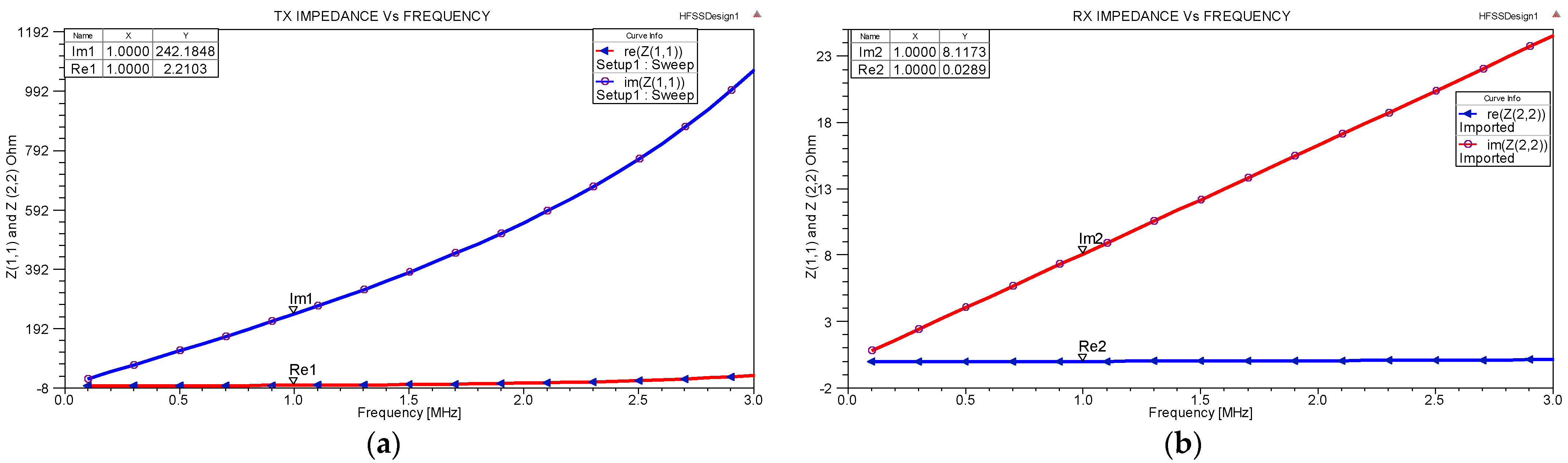
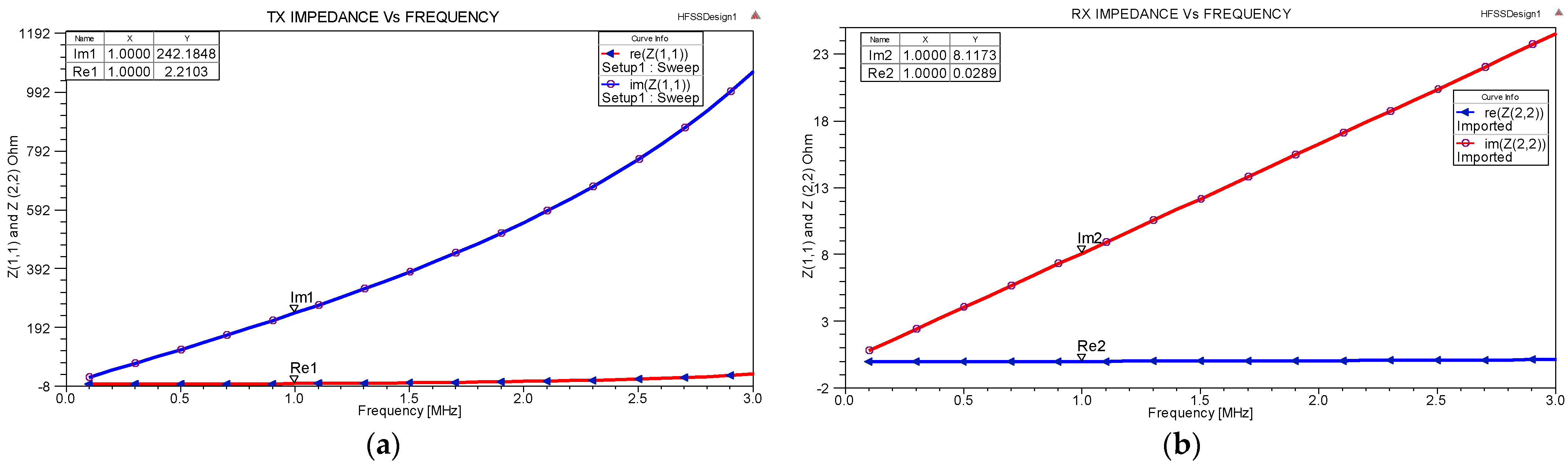
Re (
Z1,1),
Re (
Z2,2),
Im (
Z1,1), and
Im (
Z2,2) represent the real and imaginary parts of the
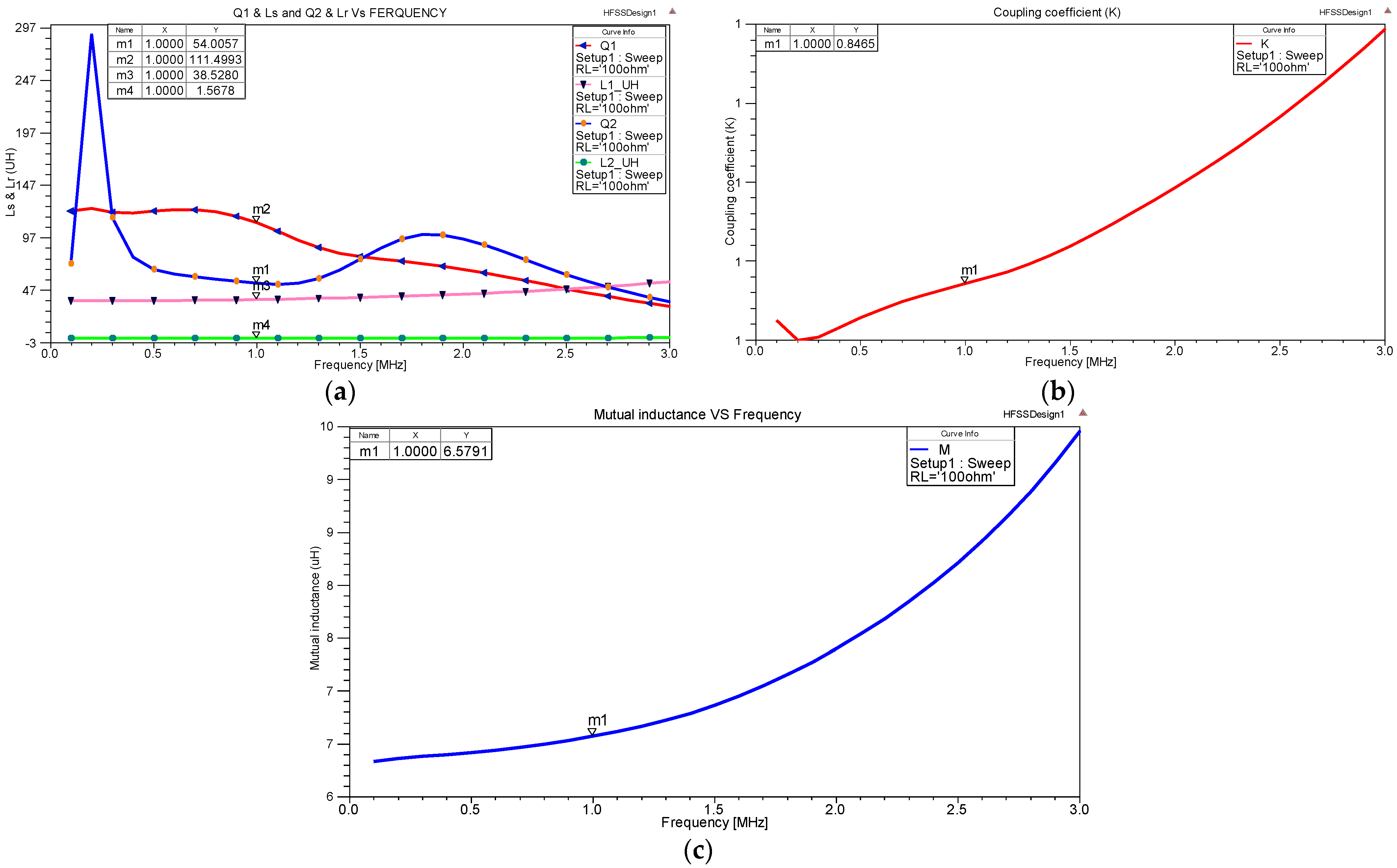
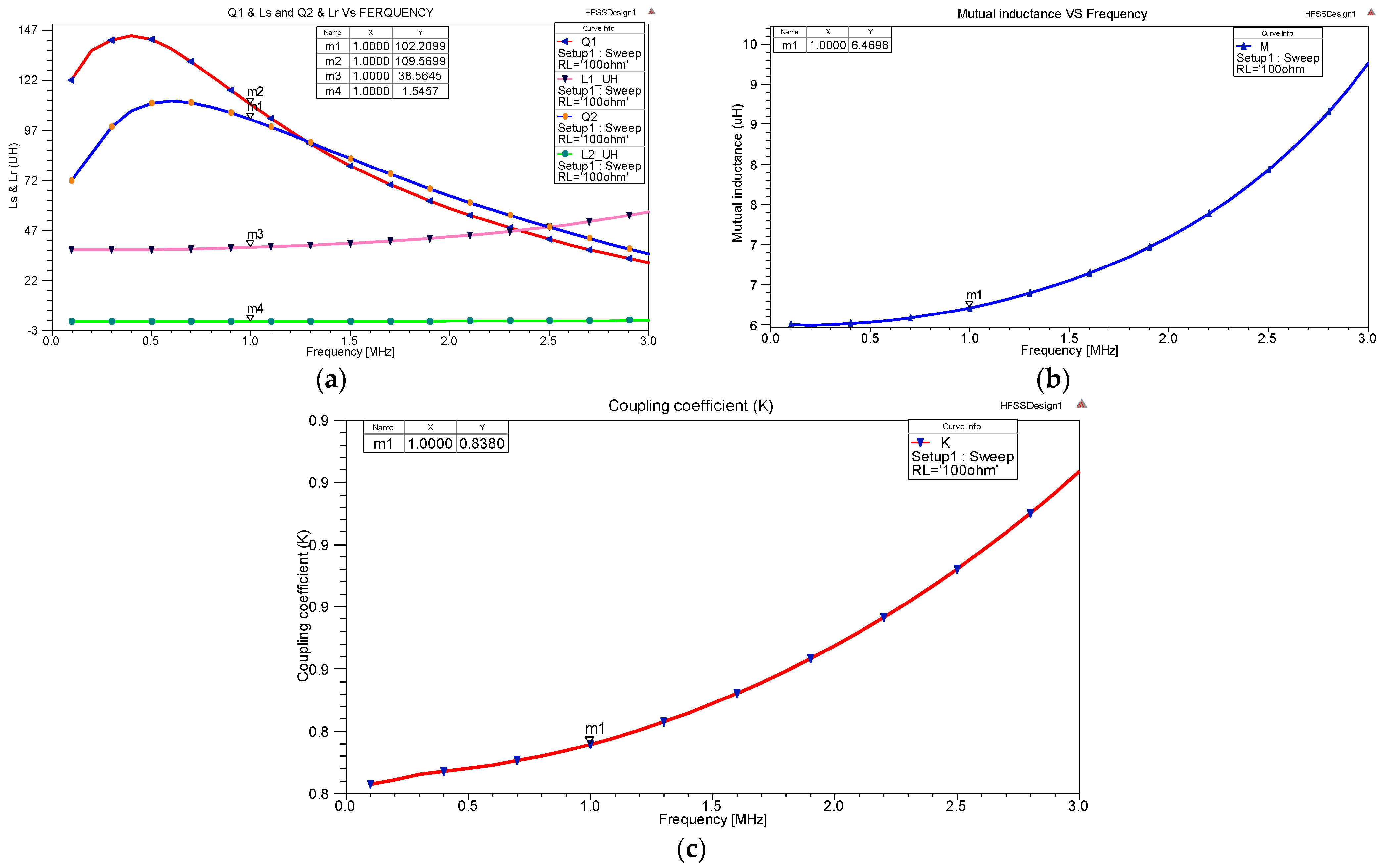
Z-parameters of both the transmitter and receiver. The quality factors of the transmitter (
Q1) and receiver
(Q2) coils are calculated from Equations (2) and (3) [
37]:
The
Im of both the transmitter and receiver coils are given as
Im (
Z1,1) and
Im (
Z2,2), respectively, while the coil
LS and
Lr can be calculated as shown in Equations (4) and (5) [
37]:
The other component, the mutual inductance (
M) between transmitter and receiver coils can be obtained from a simulation of the
Z-parameter as in Equation (6), and the coupling coefficient (
k) is calculated from Equation (7):
The maximum WPT efficiency (Max.WPTE) is represented by (
ηmax) as in Equation (8) [
38]:
The overall power transmission efficiency between the transmitter and receiver is often denoted by the transfer efficiency link (
ηlink), which will be investigated throughout the rest of this paper. Based on the
ηlink optimum load resistance level chosen according to Equation (9) [
14], the load quality factor (
QL) of the WPT system in simulation can be obtained from the following equation:
The load resistance (
RL) can be obtained through Equation (10),
where the parasitic capacitance of transmitter
(CS) and receiver (
CR) coils are presented in Equations (11) and (12) [
39].
Using ANSYS HFSS V15.03 solver simulator software [
40], STLAC and MTSCC designs can be easily calculated using
Z-parameters. The other method for improving the
QL when lowering the real part of the
Z-parameters was achieved using a high line-space (referring to the distance between each number of turns) for the resonant tube coils. However, high line-space coils are heavy, and the amount of weight a UAV can carry is limited.
In this paper, the design uses a heavy multi-tube spiral copper coil on the station’s pad for the transmitter and a low weight single-tube aluminum coil for the receiver to be carried on the drone to reduce the payload. Using a Class E PA, an operating frequency of 1 MHz was adopted to design the two types of misalignment cases (i.e., vertical alignment and lateral misalignment) in simulated and measured transmitter circuit designs.
3.2. WPT Coil Mathematical Model
The first step of the theoretical WPT design is the self-inductance for both the receiver’s STLAC and the transmitter’s MTSCC as shown in Equation (13) [
4]:
where
L is the inductance of the coil (µH),
is the vacuum permeability (
×
H/m),
m = 1 is the relative permeability of the conductor,
R is the loop radius of the coil,
NT is the number of coils turns, and
is the radius of the wire or tube cross-section. Moreover, additional values were calculated when using tube and wire coils. Equation (14) must be calculated to identify the factor parameter (
φ), outer diameter of the coil (
dout/mm), inner diameter (
din) and to find the most suitable number of turns for each coil [
41]; it ranges from 0 to 1.
Using the inductance
L of the tube coil as given in Equation (15), the same parameters were used for the copper coil to find the average diameter of the coil (
davg) and the
dout and
din values [
42]:
where
NT is the number of turns that can be calculated from Equation (16).
The coil line width (
W) can be calculated from the minor radius of each coil and
S, which represents radius change per turn for all types of coil design (i.e., STLAC and MTSCC). Utilizing Equation (17),
dout and
din can be calculated based on the
NT,
S, and
W of the coil conductor as:
Reduced distance separation between coil turns (
S) improves the magnetic coupling of the coil windings and reduces the area needed for the platform station. A large spacing is preferred to reduce the parasitic loss (
CL) and the parasitic capacitance (
Cp) between line traces of the coil turns. As it exhibits a maximum error of 13% (2 mm/
W = 15 mm) for
S ≤ 15 W, designers must carefully select the line space/line width (
S/
W) ratio. Typically, spiral tube inductor coils are built with ratios where
S ≤
W [
43].
Equation (18) is used to calculate the
Q1 and
Q2:
where
R is the resistance of the standard coil (Ω), which is equal to 50 Ω according to the Voltage Standing Wave Ratio (VSWR), and
L is the same term that was calculated in Equation (13). The quality factor can be increased in two ways, by either lowering the capacitance or the resistance as shown in the previous (Equations (3) and (4)). Capacitance is quickly decreased by either pairing a capacitor in series or by using new capacitors with a lower value. The real effect of a low capacitance is a high resonant frequency, as shown in Equation (5); this limits significant currents from voltages that have less time to overcome magnetic moment, which is the magnetic strength and orientation of a magnet or other object that produces a magnetic field, based on the definition given by Gauss or Tesla [
44].
In the near field, coil geometries aiming to optimize wireless link efficiency are affected by a set of parameters, such as a coil’s Q-factor and k, which are limited by other factors related to the fabrication technology. As the priority is to define the overall coil size constraints, the design will then indicate the minimum size features that will provide an acceptable manufacturing yield. The typical size of drone coils used is 400 × 400 mm2 and the coupling distance between the coils is 20 mm (near-field distance). As the transmitter of the coil is placed in the platform station, there is greater flexibility regarding the amount of turns, weight, and size.
Other important parameters that affect the coil size are the operating frequency (fo) and the load resistance RL. The fabrication process favors the minimum feature sizes, such as the minimum line width Wmin, minimum line spacing (Smin), minimum thickness, and the substrate and conductor material properties. The operating frequency was designated as 1MHz. In this paper, the Q-factor and k are the main parameters considered to affect the power transmission efficiency of the WPT link. These parameters are particularly impacted by the platform station’s geometric variables, such as the coil’s outer diameter (dout), spacing between the conductors (S), and the width of conductors (W) in the primary and secondary coils. Accordingly, these variables were selected for optimization to obtain the optimal Q-factor, k, and from that, the most appropriate PTE. Therefore, it is not possible to use the platform station (transmitter coil) to transfer far-field power, which is related to the design coil structure. In addition, moisture, heat, etc. also affected the transfer of energy between coils.
4. Challenges and Limitations of Misalignment Conditions for Drone Charging Platform
The WPT system suffers from reduced transmission performance during energy transmission due to the mismatch between the cores of the transmitter and receiver coils. This misalignment condition can be further classified into many types based on their simultaneous position.
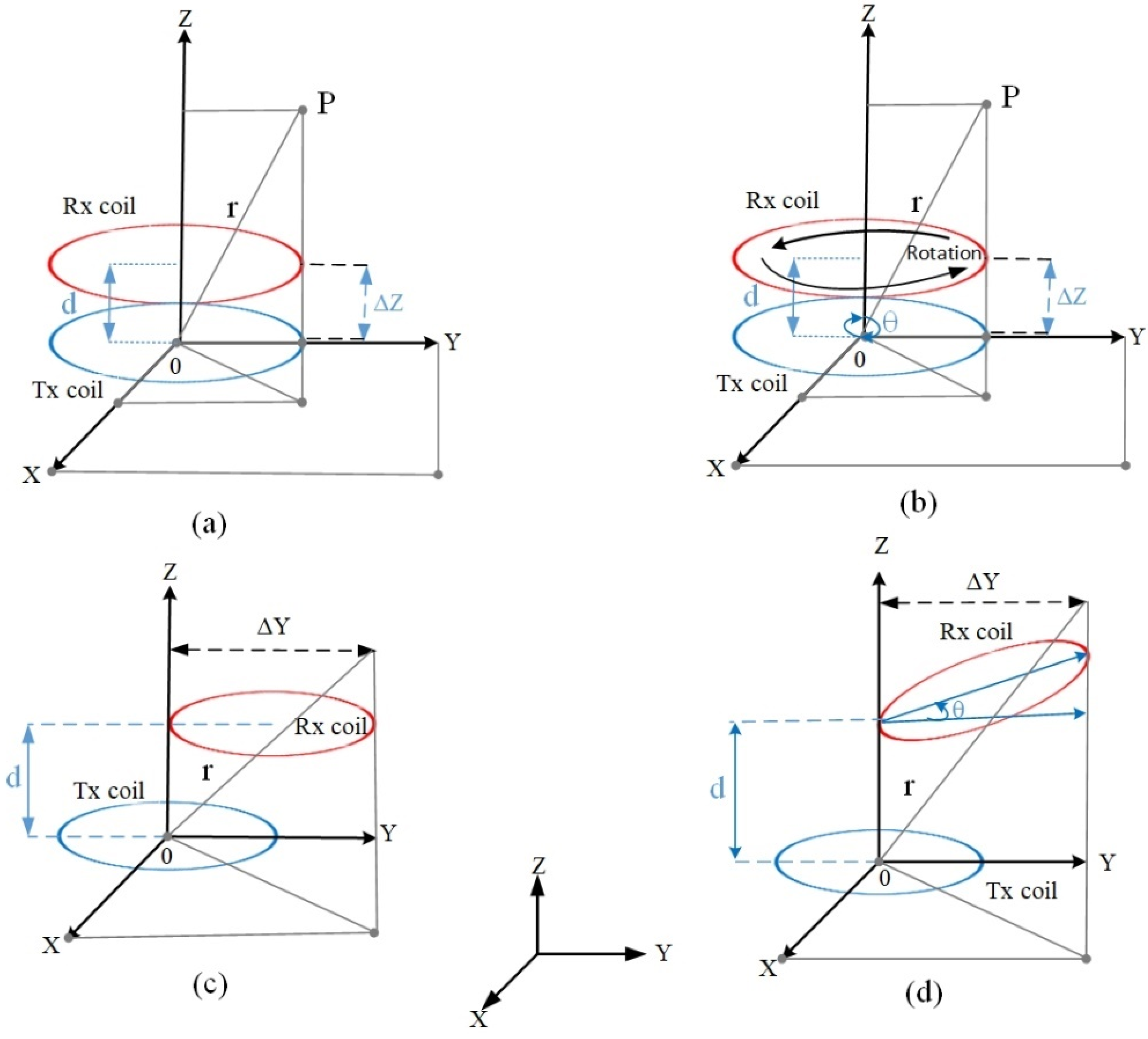
Figure 1 illustrates the various types of configuration, such as (a) vertical, (b) planar, (c) lateral, and (d) angular–vertical [
31]. Planar and angular–vertical configurations are more difficult to model for drone applications because drones are unable to hover in a static position and keep fluctuating. These configurations are more relevant for applications, such as electric vehicles, implantable medical devices, laptops, and mobile devices. Cai, et al. [
45] introduced a matrix of multiple transmitter coils for charging drones and used a current sensor (an STM32 controller) to detect misalignment.
Drones are expected to be the pinnacle of smart flying as they may act as the first respondents to any emergency that may arise. However, even without hovering in the wrong directions, they have a low-power density. Thus, a long sustained flight is impossible [
16]. To optimize energy transfer performance, the misalignment transmission distance between the transmitter and receiver coils is the main limitation of MRC methods, which are sensitive to transmitting and receiving coil alignment. However, this is limited by the diameter (large or small),
NT, line spacing of each coil, and distance between the transmitter and receiver coils [
17]. Researchers have been attempting to reduce misalignment using two major approaches [
18]. The first approach is the auto-alignment of the two coils either by the transmitter or receiver coil movement, and the second is through electrical manipulation, such as resonance or modifying compensation topologies. Regardless, major challenges in the adoption of WPT technology still exist.
IC and MRC methods have the main advantages of high-power and long-distance transmission through different power amplifier types of far near field applications. However, the IC and MRC systems must deal with the inevitable key technical problem, which is the extremely loosely coupled effect between the transmitter and receiver coils. This corresponds to the measurement results found by [
46], where
k was mostly found to be much less than 0.01 within transmission distances of between 2 m and 12 m. Their experimental model can provide 10.3 W of power at up to 7 m distance, at a frequency of 20 kHz using dipole-coil-based IPT [
47]. Therefore, the transmission air gap difference is another key technical concern for MRC systems because of the resonant frequency.
In other studies, several attempts using the multi-loop topology in impedance matching have been made to ensure the MRC state, even with a differing distance between the transmitting and receiving coils, to reduce the input impedance variation [
34]. The technique developed by MIT researchers is a method of highly resonant magnetic WPT which reduces the misalignment problem to a certain extent for a 2 m transfer distance [
35].
6. Experimental Configuration of an MRC Misalignment Coil
The WPT system is intended for charging drones in various unmanned and remote applications such as remote monitoring. The WPT circuit considers the S–P topology connection of a 1 MHz resonance frequency. This approach uses coil structures, such as dout and din to solve misalignment conditions. The MRC of the STLAC (receiver) and MTSCC (transmitter) coil types have been suggested to generate strong magnetic field leakage. Thus, a laboratory test on the MRC hardware design was conducted to validate the transfer distance and efficiency between the transmitter and receiver coils, using the highest performing coil design obtained from the simulation.
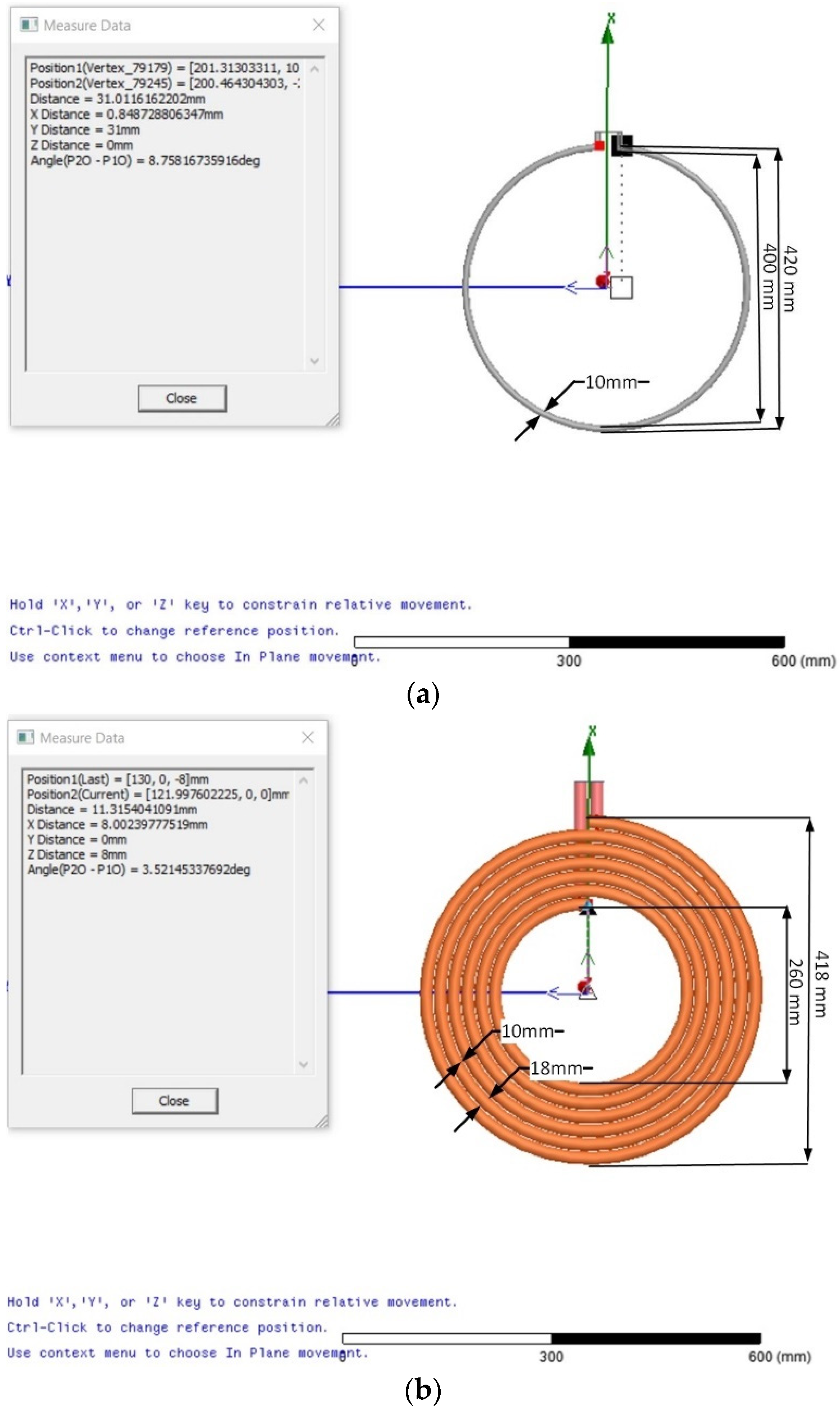
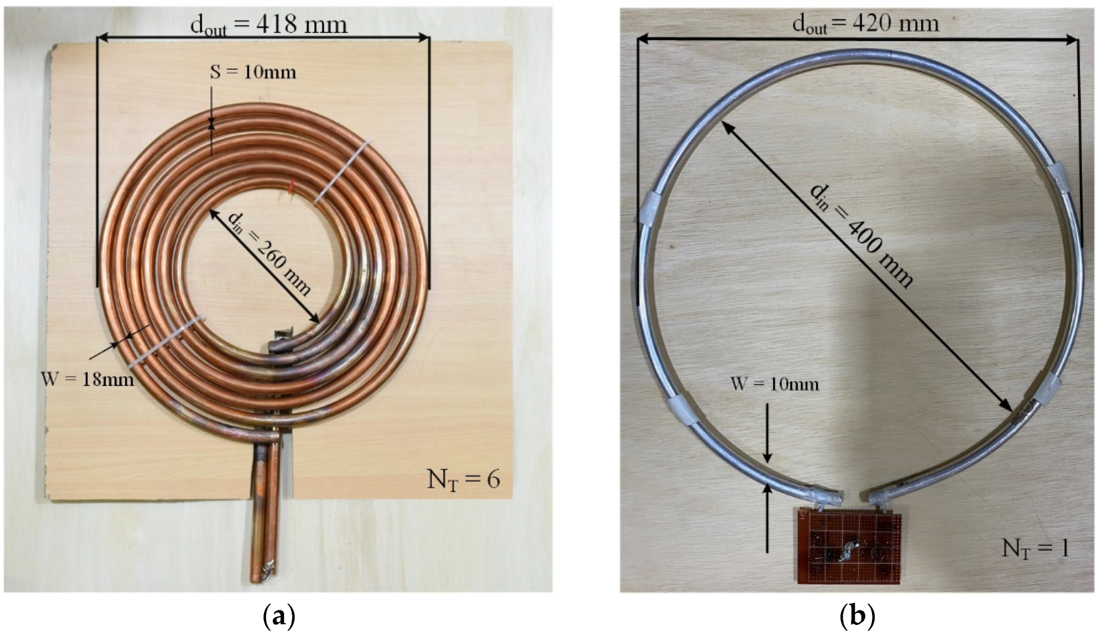
First, copper and aluminum loops of 420 mm (
dout) were used to design one turn. The inner coil diameter (
din) was 400 mm, and a line distance width of 10 mm was used. The receiver coils were mounted on the wooden pad for laboratory testing. A circle of
dout = 418 mm and
din = 260 mm was chosen to be identical to the asymptotic diameter of the transmitter coil. Then, a circular frame was constructed to design the transmitter coil and make the copper into a circular shape, as shown in
Figure 5a. As mentioned previously, the circular shape promotes increased transfer efficiency by providing a more enclosed space (area) for a given distance (perimeter) than a square. The aluminum coil was chosen for the STLAC to ensure the lightweight of the receiver coil and maximum transfer power.
Figure 5a,b display the designs of the transmitter and receiver coils with
dout,
din,
NT,
W, and
S.
The implications standard of the present study in Class E PA switching was the use of constant envelope modulation techniques, such that the signal does not carry any amplitude information because of the assertive amplitude compression suffered in PA switching [
49]. The transmitter and receiver coil matching network accounts for a great portion of the power loss. A great matching network design between PA and antenna coils is necessary. Therefore, all the power is delivered to the load. Various architectures are available for constructing a power amplifier that converts DC–DC voltage, such as Class E PAs [
50]. The efficiency does not represent a physical parameter, it is only helpful for showing the requirements of the circuit for matching and stability. The advantage of Class E PAs is: (1) they have simple architecture and need only one active device; (2) their frequency range is wide KHz–MHz; and (3) they have high power transmission efficiencies. However, the disadvantage of Class E PAs is that any shift in resonance frequency will decrease the output power transmission appreciably.
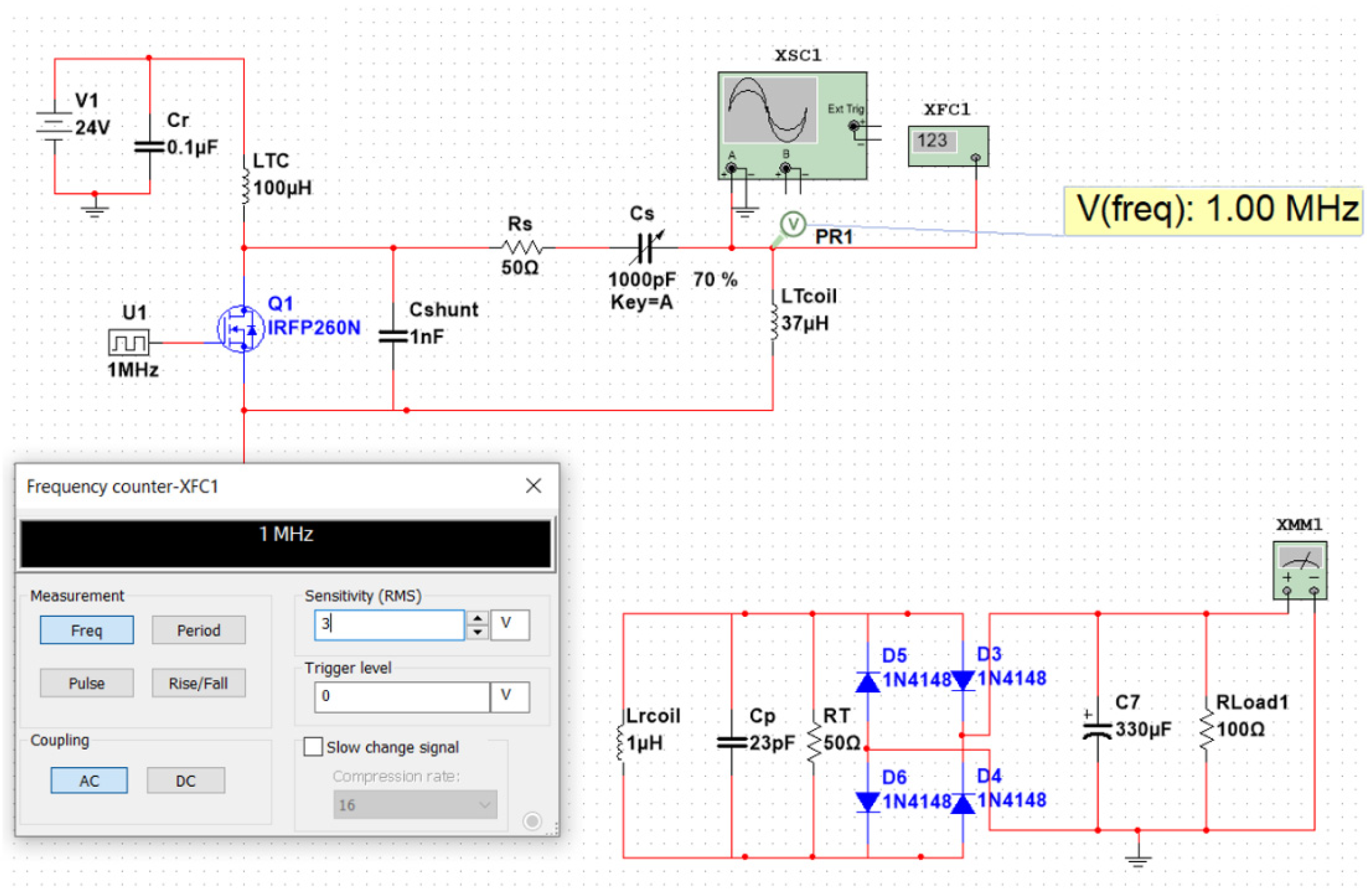
Figure 6 shows the matched resonance frequency obtained between the transmitter and receiver circuit using the Multisim software for electronic circuit design.
The best design from the two configurations (vertical and lateral) was implemented and experimentally tested as MTSCCs and STLACs. The parameters are stated precisely in
Table 1 and
Table 2. The first and second MRC experiments were conducted under loaded conditions. Usually, the resonant wireless power transfer systems require over 1 MHz frequency to get higher efficiency, and it is very complicated to implement such a high frequency because of losses in high frequency alternating current supply. However, lab hardware only allows high-frequency industrial standards to be used, which means the current hardware and tools cannot be upgraded to support higher-frequency industry standards [
51,
52]. Additional improvements include increasing the frequency to 1 MHz and raising the transfer efficiency. Therefore, 1 MHz is used in the designed model [
53]. The usage challenges encountered in the relatively low-frequency range of 1 MHz can be described as follows: (i) reduced transmission efficiency; and (ii) increased size of the transmitter and receiver coils [
54].
A substantial enhancement in the coil design of the proposed WPT system is observed by considering the misalignment between the transmitter and the receiver coils. In this study, a Class E PA was used. This enabled (i) a simple architecture with only one active device, (ii) a broad frequency range (kHz–MHz), and (iii) a high power transmission efficiency of 90–95%. For frequency regulation, a series-to-parallel (S–P) topology compensation was chosen. The input circuit consists of an MTSCC transmitter coil connected to an oscillator circuit (i.e., 43.24 V/0.43 A) with a DC input voltage and current (i.e., 24 V/1.08 A) that generates oscillations, where according to some of the tests that have been conducted for building an oscillator circuit, the best transistor type is IRFP510N. The voltage that is available to the input circuit can be increased using three metal-oxide-semiconductor-field-effect transistors (test: IRFP250N, IRFP460LC, and IRFP510N), two parallel coupling capacitors, a capacitor shunt, and one radio-frequency choke coil. The STLAC, four parallel coupling capacitors for testing, a bridge rectifier, a resistance load (100 Ω/50 W) for testing, and a charging controller to charge the drone’s battery with a proper voltage (i.e., 24 V) are the primary components of the receiver circuit, as indicated in
Table 1 and
Table 2.
The most significant objective in this test is to find the resonance (matching network) between the transmitter and reception coils by determining the optimal capacitance and resistance values for both coils’ inductance values. For the X525 quadcopter drone, this research uses a 22.2 V/5500 mAh Li-Po battery. The drone’s battery is charged using the receiving coil. The STLAC and MTSCC parameter requirements are supplied in
Table 3, and the measurements and computations are reported in
Table 4.
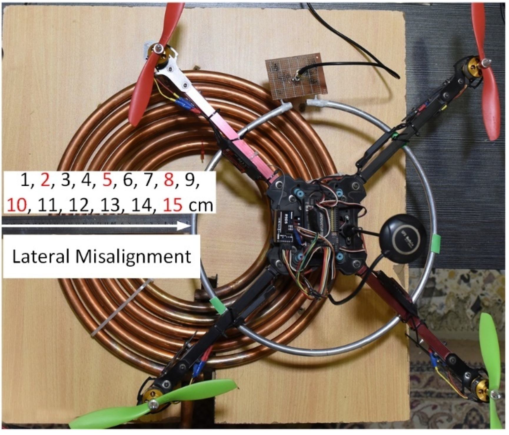
Next, the coil was rounded until the required turns were achieved (
Figure 7). The coil’s ends were then welded with oxygen welding. However, the coaxial port was welded with a Veroboard to avoid poor conduction. In this study, the ideal coil is considered as having high transfer power and efficiency, while being of suitably low weight as not to hinder flying drone performance. The transmitter coil was made from copper and glued on the pad with a small amount of inlayed plastic around the coil to improve the inductance with the perfect design of spaces between turns.
6.1. Alignment and Misalignment Configuration
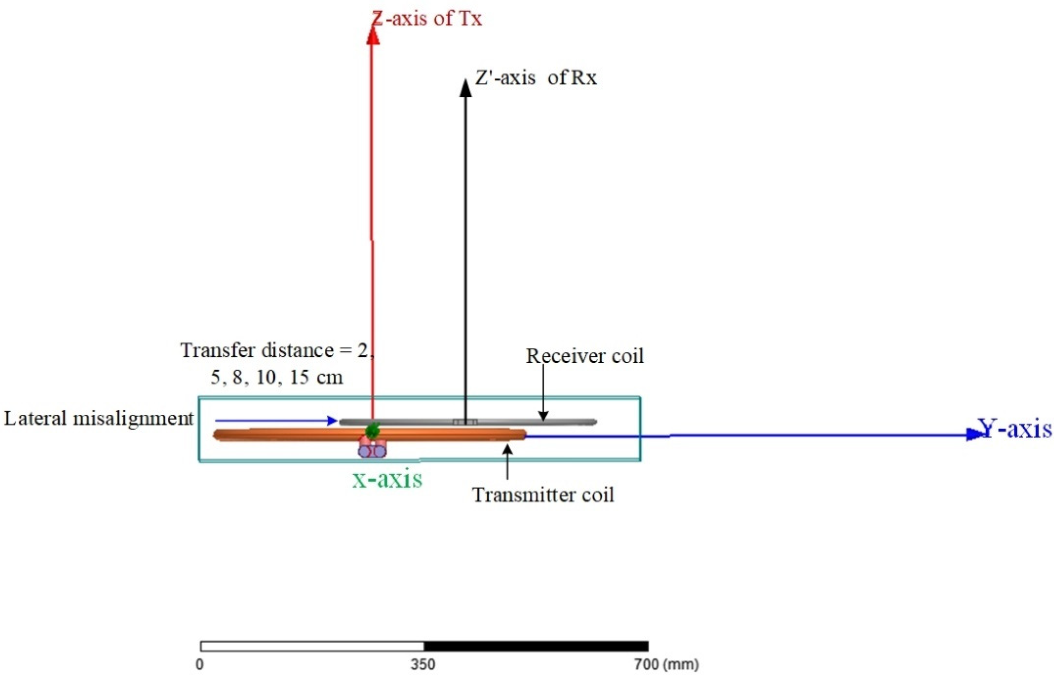
This work achieved the reduction of the misalignment problem from the lateral configuration by adopting a large primary and secondary coil configuration. The receiver coil was configured as an STLAC with one turn and was employed alongside the receiver circuit with the transmitter coil (i.e., MTSCC). Five different misalignment distance values were selected as 2, 5, 8, 10, and 15 cm (
Figure 7: red color), and other distances were almost the same value at 2 cm of the vertical distance between receiver and transmitter coil, which were experimentally tested to evaluate the energy transfer performance. The pad of the base station was implemented to ensure a lateral misalignment of not more than 15 cm between the transmitter and the receiver coils, as shown in
Figure 7. The transfer power and efficiency were measured for these distances during drone landing. The direct current (DC) and voltage were measured with 2 cm of air gap fixed in vertical alignment. However, the DC output power and transfer efficiency were calculated when the drone’s battery loaded the receiving circuit.
6.2. WPT Experiment Configuration
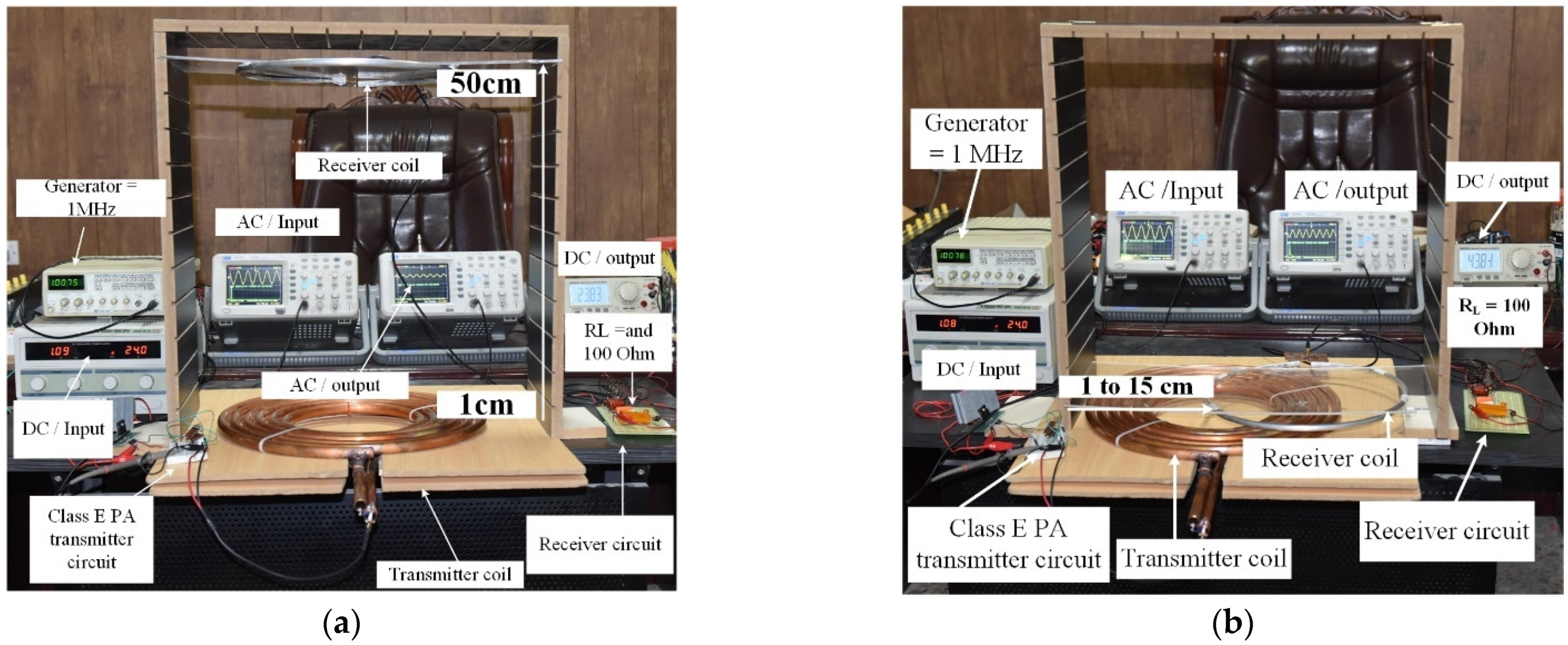
The test was mounted using a digital multimeter (DT9205, Dowdon, Shenzhen, China), an oscilloscope (MCP Lab Electronics/DQ7042C, Shanghai MCP Corp, Shanghai, China) and a transmitter using a DC power source (Q-5010S, EMIN Group, Yangon, Myanmar). In both the vertical and lateral configuration tests, the MTSCC was constant, whereas the STLAC was varied based on the different sized air gaps. Several air gap steps were adopted in our experiments due to the proposed loaded and unloaded WPT system, wherein the transfer power and efficiency were decreased to a large extent after 15 cm in the loaded system. For each position, the transfer voltage, current, power, and efficiency were measured with respect to the distance. The measurements were conducted in a laboratory to test the force sensor of the vertical alignment solution, and lateral misalignment distance when the drone landed on the platform stations.
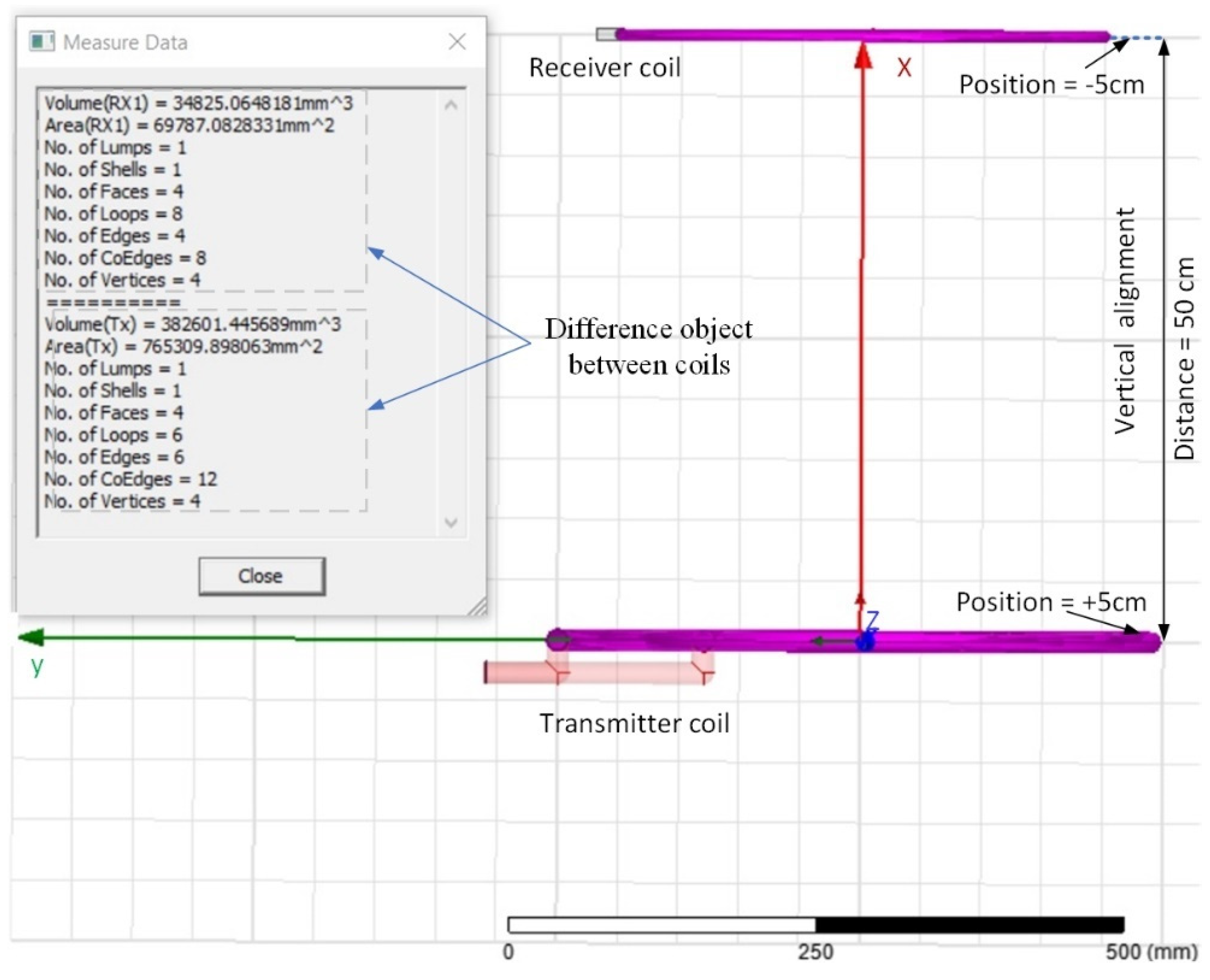
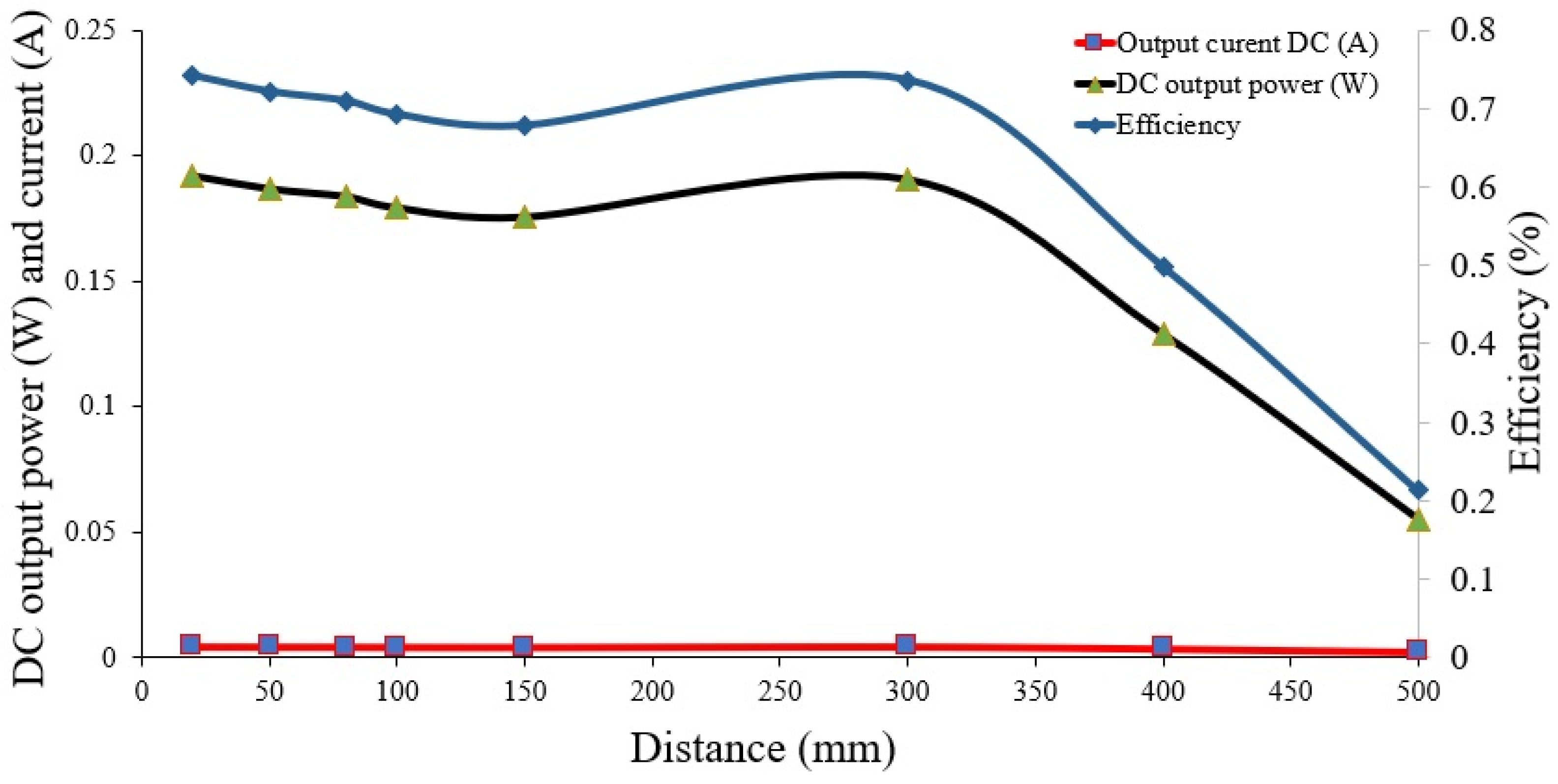
First Experiment: This experiment was for a vertical alignment system with a 100 Ω load. In vertical alignment, air gap/transfer distance measurements of 2 to 50 cm were considered. The MTSCC was tested with the second coil consisting of a one-tap (i.e., an STLAC with one turn). The number of turns was selected based on the first and second simulations, wherein a tradeoff between coil weight, transfer power, and efficiency was achieved to obtain an acceptable transfer performance and weight.
Figure 8a shows an example of the vertical alignment improvement in transfer distance between 2 cm to 50 cm when
RL = 100 Ω.
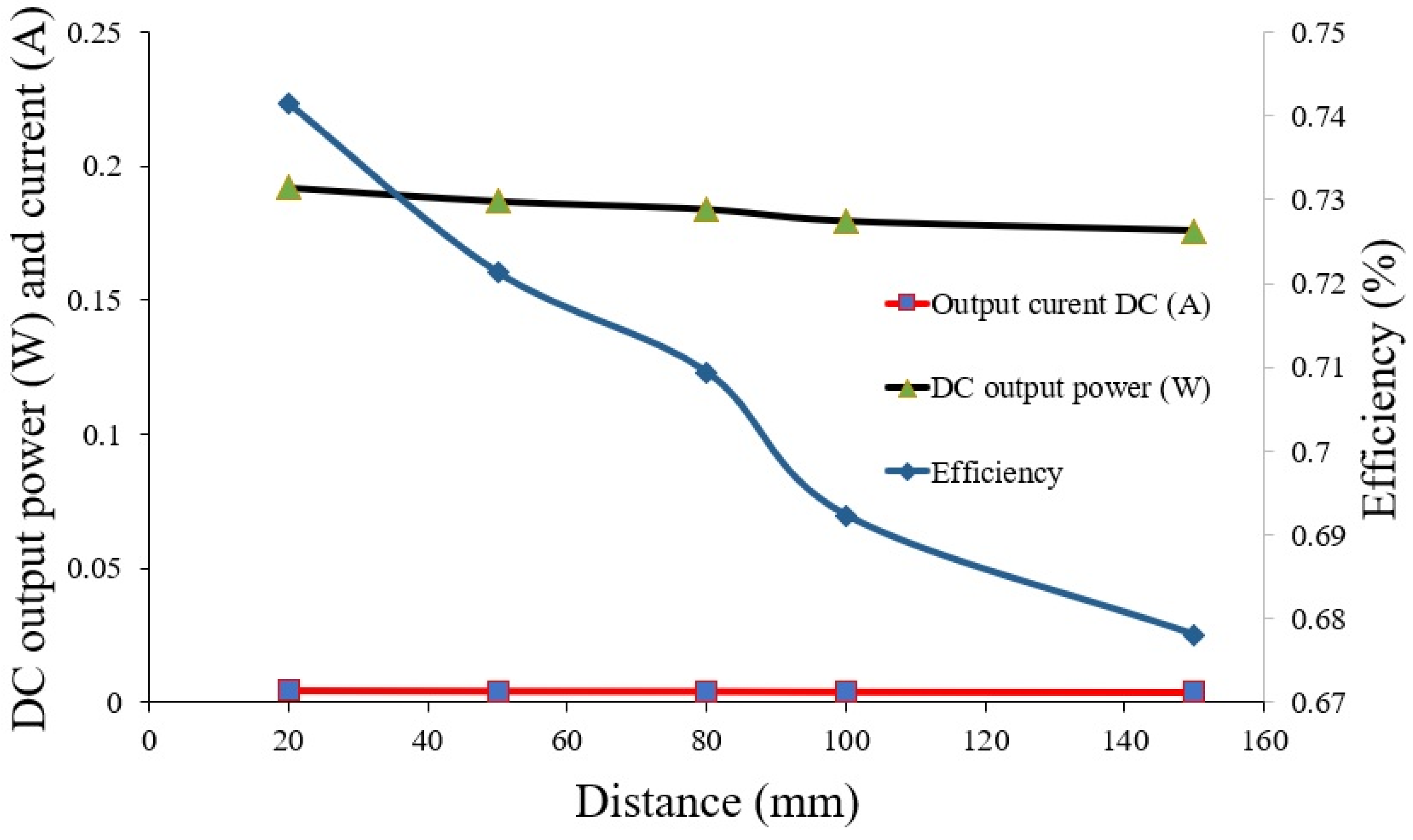
Second Experiment: The experiment for a lateral misalignment system with 100 Ω of load, on a pad size of 60 × 60 cm
2. A total of five lateral misalignment distances (selected distance, e.g., 2, 5, 8, 10, and 15 cm) were investigated in this experiment.
Figure 8b shows lab measurements for 1 and 15 cm of minimum and maximum lateral misalignment distance range values available in the platform station space.
The payload of the drone also poses a challenge to this design. Consequently, the receiver coil (STLAC) and the breadboard’s weight in the receiver circuit were reduced as much as possible to 0.0105 and 0.0015 kg, respectively. The final total weight of the drone was 1.377 kg. The receiver coil only takes up 0.785% (i.e., 0.0105/1.337 × 100%) of the drone’s weight, while the total payload (aluminum coil and breadboard with receiver circuit) takes up 0.89% (i.e., 0.012/1.337 × 100%). The measured weights for parts of the drone and coil are listed in
Table 5.
6.3. Detection of the Drone on the WPT Circuit
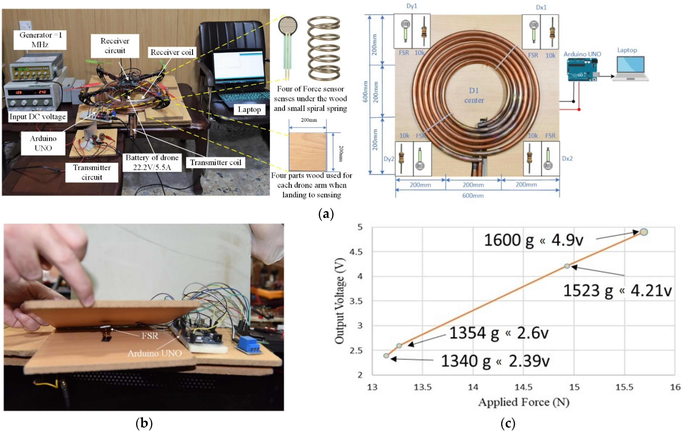
To detect the drone landing in the experiment, a four FSR sensor configuration, which was adapted from [
29,
38,
55] was set up on the squared platform (
Figure 9a). The sensors were installed at the edges of the platform using a small spiral spring and 20 × 20 cm
2 of wood (
Figure 9b). The wood’s weight will be increased when a drone lands. An Arduino UNO and the four FSRs (i.e., Dy1, Dy2, Dx1, and Dx2) were connected to the platform station to start charging when the drone lands. The Arduino functions to read the signal from the FSR, convert the signal to the equivalent weight, and finally reduce the power consumption using the sleep/wakeup strategy. In addition, the regulator and relay circuit required for each voltage, which depends on the drone’s weight, can sense the FSR that is needed to charge the drone.
The calibration of the FSR before drone landing was tested in the lab, as shown in
Figure 9c, and was based on four different drone weights. The four weights (i.e., 1600, 1523, 1354, and 1340 g) were converted to Newton (N) units and are presented on the
x-axis as the applied force. The
y-axis presents the output voltage for each sensor’s force measurement (4.9, 4.21, 2.6, and 2.39 V).
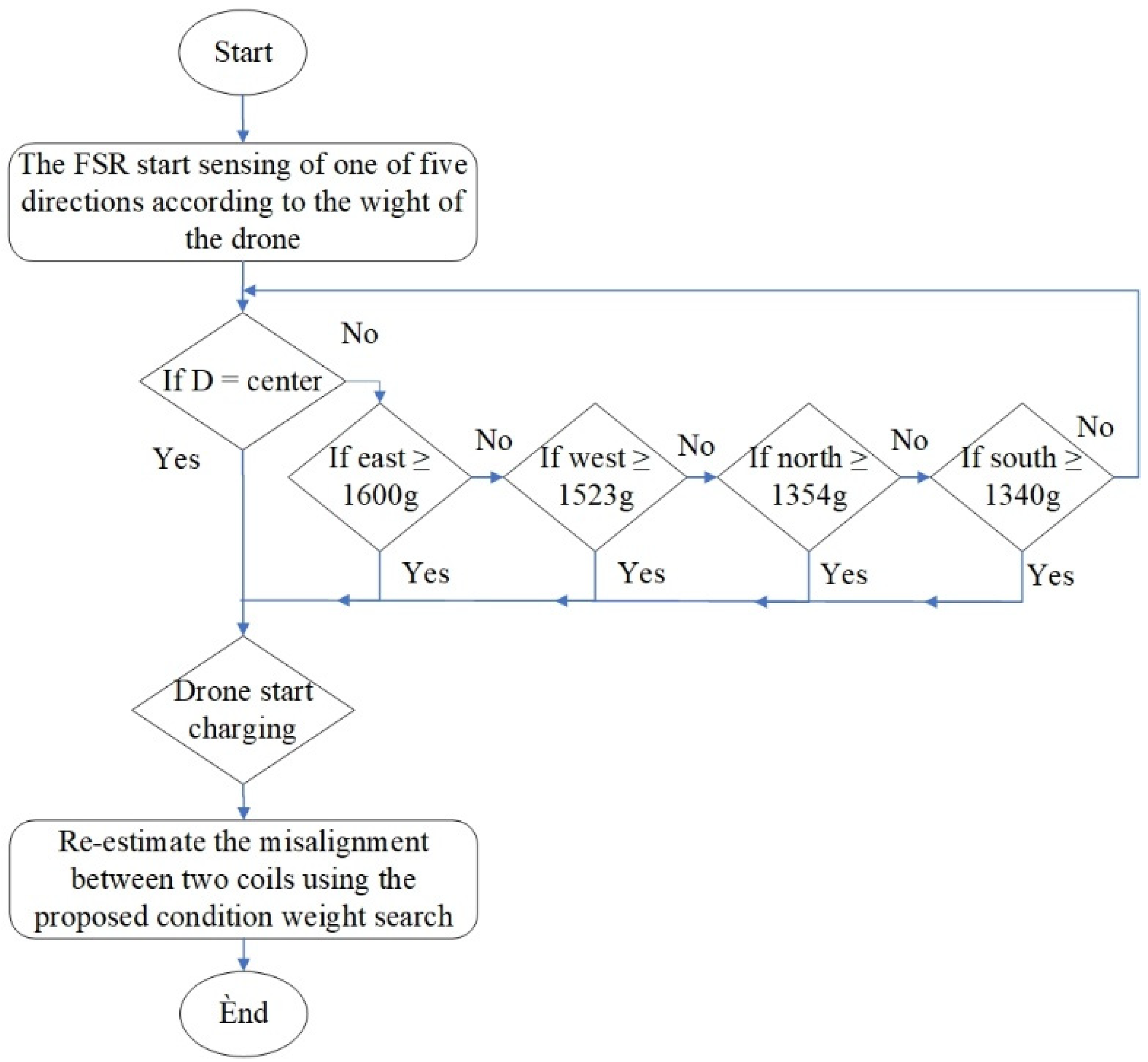
Figure 10 describes all the possible directions that platform stations may have in lateral misalignment to charge a drone based on WPT. The FSR measures the threshold weight value of the drone (i.e., 1300 g). The first direction (D) is the center of the platform station, where it is in vertical alignment. In addition, the lateral misalignment is represented by the four weights based on direction (i.e., east = 1600 g, west = 1523 g, north = 1354 g, and south = 1340 g), according to the platform size (60 × 60 cm
2) used in this work. The four directions of the different weights measured during the drone landing test conducted in the lab can enable the charging of the drone battery for different durations. However, the lightweight direction (such as 1340 g) will be the best for charging the drone’s battery. The misalignment distance is essential to efficiently determine the weight trend of the drone, as well as the wirelessly transferred power of stationary MRC charging at all power levels according to the FSR technique, which operates by the programming of the four directions into the Arduino UNO. This proposed misalignment algorithm is suitable for any power level designed for drones and can improve transfer efficiency.
8. Conclusions and Future Works
This study has designed and implemented an MRC-based solution for a near field wireless power transmission (WPT) drone charging station for remote and unmanned applications, such as radiation monitoring and smart agriculture. The MRC design was distinguished by combining the use of an STLAC on the receiver/drone with an MTSCC on the charging/receiving platform to address transfer power optimization and increased efficiency issues. Several coil designs were assessed in the simulation phase to identify the suitable range of drone position misalignment due to the air gap in wireless charging.
For the simulation, the Class E PA model was designed to test misalignment coils and simulation results were obtained using HFSS 15.03 software. The design resulted in the improvement of vertical alignment transfer power. The results were validated mathematically and in a simulation to demonstrate a tailored MTSCC design with an improved Q-factor. The transfer efficiency was 94.58% with a 2 cm air gap distance. The lateral misalignment performed at 94.95% transfer efficiency at values of 2 cm.
When referring to the WPT battery charging system, the coils are usually not aligned, limiting the potential of WPT for future remote applications. The results show that transfer efficiency differs between simulation and measurement for vertical alignment by around 13.08%, and lateral misalignment differs by around 20.8%.
Based on simulation and experiments, a number of six turns in the coil (MTSCC) was selected for a new spiral coil in the transmitter circuit to improve transfer distance and efficiency in relation to lateral misalignment. In practice, STLAC was selected for payload improvement purposes. It also provides the maximum transfer power, efficiency, and range from the source of electricity to the coil in the drone, while also being lightweight.
The misalignment condition is vital for drone charging if they are to be implemented for energy-efficient radiation monitoring and internet of farming technology applictions. Future experiments could use a higher operating frequency in the transmitter circuit to reduce the coil size, NT, and weight of the receiver coil mounted on the drone. This has the effect of increased transfer efficiency and output power, and reducing distance in WPT. Additionally, MRC-based WPT requires additional studies to enhance the design of the resonators for large-distance transfers and maximum power transfers during angular and planar charging that will reduce losses in the system.
This study focuses on vertical alignment and lateral misalignment cases. The other two types of drone misalignments (i.e., angular and planar position) are not considered in this work due to hardware limitations. In addition, the results were proposed in sunny weather (summer season in my country) to improve the conditions for solar cell electricity generation, and to maximise transfer power.
However, it is worth investigating the extent to which a single tube in the receiver and multi-tube coils can affect system efficiency in the transmitter coil as part of future work. Additionally, the thickness of the tube coil can affect transfer efficiency when the frequency is 1 MHz. Two materials were investigated and the impact of the number of turns and thickness of the receiver coils were analyzed. However, the most important aspects were: the low weight of the receiver coil (0.0105 kg); and the harmonizing of the inductance and capacitance of the transmitter coil to make a matching circuit between the two coils.
In addition, MRC can be used for mid-range applications (e.g., charging the WSN or UAV) with suitable transfer distances and transfer efficiencies. However, the flight time of the UAV is restricted because of the limited battery capacity. Therefore, the MRC-based WPT offers a good solution to charge the drone battery. Thus, the flight time of the drone can be improved using the STLAC (receiver coil) and MTSCC (transmitter coil), whereas the transmitter coil was designed according to the simulation to increase the transfer power and efficiency while charging the drone battery; the receiver coil was designed in the lab to overcome a heavy payload.
Finally, the k and Q-factor of the adopted STLAC can be modified, for example, by using a different coil diameter, increasing, or decreasing the NT, or using a cover shield between the transmitter and receiver to charge the battery for certain applications, such as drones and cell phones, efficiently. Thus, the battery lifetime of the drone can be increased. Furthermore, the designed coil could be chosen by considering the limitations of the coils to improve the performance metrics.


 ,
, 


