Article

Development and Experimental Implementation of Active Tilt Control System Using a Servo Motor Actuator for Narrow Tilting Electric Vehicle

by
Mustafa Karamuk
1,* and
Orhan Behic Alankus
2
1
Ford Otosan R&D Center, Istanbul 34885, Turkey
2
Department of Mechanical Engineering, Faculty of Engineering and Sciences, Tuzla Campus, Istanbul Okan University, Istanbul 34959, Turkey
*
Author to whom correspondence should be addressed.
Submission received: 31 December 2021 / Revised: 3 March 2022 / Accepted: 3 March 2022 / Published: 9 March 2022

Abstract

:
Light electric vehicles are alternative solutions to passenger cars in terms their lower costs and space saving in city traffic. Narrow tilting vehicles (NTV), known also as three–wheeled vehicles, can be equipped with an active tilting stability controller that tilts the vehicle automatically during cornering to enable lateral stability. There are mainly direct tilt control (DTC), steering tilt control (STC), and combined DTC–STC methods described in the literature. The DTC method is typically applied up to 10 km/h vehicle speeds. Considering city traffic and frequent start–stop cycles, the DTC method needs to be improved in terms of lower actuator torque and energy consumption. DTC can be designed by using either hydraulic or servo motor actuators. In state of the art, the servo motor actuator has not been studied in detail considering its integration and application aspects. Mostly, the actuator has been considered as a black box model. Proposed control method in this study enables improvements in the direct tilt control system (DTC) in terms of reducing the actuator peak torque and enables the application of DTC at higher vehicle speeds. Regarding the modeling of the electric actuator, a permanent magnet synchronous motor and field-oriented control model are also included in the simulation model. Modelling of the electric actuator enables accurate representation of actuator dynamics. In this way, battery Ah capacity can be sized and energy consumption of the electric actuator can be calculated for a given drive cycle. To this end, objective of this study is to design a direct tilt control method including the electrical drives and motion control concepts. In this way, an application methodology of the servo motor actuator is developed and implemented on a narrow tilting three-wheeled electric vehicle. Interactions between tilt control system and the servo motor actuator system are described from practical aspects.

1. Introduction

Active tilting stability control systems are a driving assistance system that prevents the rollover of narrow tilting vehicles (NTV) while turning a corner.
There are mainly direct tilt control (DTC), steering tilt control (STC), and combined DTC–STC methods, as studied in [1,2,3,4,5,6,7,8,9,10,11,12,13,14,15]. They can be designed by using a hydraulic or a servo motor actuator.
Considering the traffic and frequent start–stop cycles in cities, there is frequent need for tilting, also known as leaning support, at low speeds, which means that the DTC method needs to be improved in terms of lower actuator torque and energy consumption.
In this study, DTC is preferred over STC because DTC can work better than STC at low speeds; the control method is straightforward and it can work on slippery roads better than STC. Application of STC requires a steer-by-wire mechanism, which means decoupling the driver’s steering input from the steering column. There are commercialized applications of DTC by several companies: GM, Ford, and Carver, as given in [7].
Combination of DTC and STC is studied in [1,2,11]. However, control problems are even more complex than STC or DTC alone. There are no experimental studies combining DTC and STC and actuator control. Control mode changeover between DTC and STC is the most difficult problem.
The contribution of this study can be summarized as follows:
  • A DTC controller is developed using state feedback control with pole placement design technique. Unlike the PD controller proposed in [1], a derivative term is not used. The proposed controller is less sensitive against noise.
  • The state feedback controller is improved by combination with a first order reference model. In this way, further reduction in actuator torque and perceived acceleration can be achieved.
  • Detailed design inputs for the servo motor actuator and tilt control are studied.
  • DTC configuration given in this study has a servo motor having 400 W rated power at 24 or 48 V DC input. The proposed configuration can achieve tilting up to 8 m/s vehicle speed without exceeding motor’s continuous torque.
  • Simulation and experimental verification on a three-wheeled electric vehicle are carried out.
This paper is organized as follows:
  • Section 1 provides a review of the state of the art, summarizes technological problems, and compares the hydraulic and servo motor actuators.
  • Section 2 describes the application methodology of the servo motor in the DTC system. Control modes of the servo motor, critical design inputs, and integration into the tilt controller are studied. A prototype vehicle configuration and control configuration is described. Section 2 can also be considered as the conceptual design phase of this study.
  • Section 3 describes the design of the tilt controller and state feedback control law by pole placement design technique. Simulation results in Matlab–Simulink are presented.
  • Section 4 presents the software implementation steps and experimental results.
  • Section 5 presents the conclusions and possible future tasks.

1.1. Brief Review of the State of the Art in Tilt Control Technology

Active tilting control of a three-wheeled vehicle should provide functionalities such as preventing rollover of the vehicle during cornering, and assisting the driver to follow desired lateral trajectory.
Research and studies have established theoretical background, simulation and experimental data on tilt control technology [1,2,3,4,5,6,7,8,9,10,11,12,13,14,15,16,17,18,19].
In the DTC method proposed in [1], the tilt angle reference is calculated based on lateral acceleration, which causes an inherent delay in the control loop of the DTC [15].This inherent delay increases the transient torque requirement of the actuator [7,12,15,16,18].
Another major concern on DTC is the higher actuator torque and power demand and hence higher energy consumption owing to the direct control of the tilting axis [7,11].
Therefore, improvements in DTC are required to provide faster actuator torque response to compensate for the inherent delay between measurement of lateral acceleration and production of actuator torque. Comparison of the DTC and STC methods have been studied in [11,16].
In the current state of the art, modeling and integration of the servo motor actuator into the tilt control system and energy consumption have not been studied in detail. There are studies on hydraulic actuators including simulation and experimental verifications [7,12].
In [13], a brushless DC motor controller was designed for the STC system with special focus on power electronics and software design. A state feedback method by pole placement technique was developed for STC control [13]. System states are the tilt angle, tilt speed, lever angle, and derivative of lever angle.
Regarding the controller type, a proportional derivative (PD) controller was proposed in [1,3,9], and a receding horizon controller (RHC), i.e., model predictive controller (MPC), was proposed in [6]. The RHC proposed in [6] aims to start tilting before the cornering begins. In this way, actuator torque and perceived acceleration can be reduced. In [8], a PD controller with a prefilter on control reference was proposed; In [10], a PID control including tilt position and tilt rate control was proposed. In [15], LQR/LQG control with state feedback, in [16] H2 optimal control with state feedback was studied and detailed mathematical analysis was given with simulation results. In [16], lateral speed, yaw rate, tilt speed, tilt position are given as system states and steering input is also included to calculate the tilt control reference.
In case the steering input is included to the control reference in DTC method, the tilt control algorithm should ensure that the vehicle can be moved back to a nontilting position when cornering is completed. Because of the mechanical link between the steering system and vehicle body, there is a possibility that the servo motor controller can continue to follow the initially applied position reference.
In [20], a review is given on tilt control systems. In [21], critical states of the vehicle such as normal driving, one rear wheel temporarily lifted off the ground and totally falling down of the vehicle were analysed. In more recent studies, model predictive controller (MPC) with actuator constraints was proposed for tilt control in [22]. In [23], a nonlinear tilt controller was developed to compensate for nonlinearities of tilting dynamics. In [24], MPC for tilt control was studied using a hydraulic actuator integrated into the left and right wheel suspensions. In [25], multibody dynamic models of a three wheeled vehicle, LQR control, feedback linearization, and MPC were studied. In [21,22,23,24,25], detailed simulation studies are given. As well known in control theory, MPC has high complexity for real-time control as the prediction horizon increases. High computational complexity increases the sensitivity of the controller against the noise in measured signals. In [26], LMI-based H2 control with constraints on actuator torque has been studied.
The objective of this study is to provide application methodology to develop a complete tilt control system by using a servo motor actuator. State feedback control by pole placement is preferred owing to its straightforward control design and practical software implementation.

1.2. Summary of Technological Problems

Important problems in an active tilt control system are summarized below. In Figure 1, critical system integration parameters are also illustrated. The tilt controller can perform in an optimal way if all system parameters are configured correctly.
(1)
Stability control
  • Speed limitations of DTC and STC methods: Model changeover and bumpless transfer are problems of the combined DTC–STC method. Using a DTC and STC combination requires separate actuator design, high computation effort, and extra cost.
  • Limited stability margin of PID and PD controllers: Instability or performance degradation may occur in the case of variation of vehicle mass, roll inertia, suspension stiffness, and vehicle speed.
  • Performance of tilt controller in discrete form for a given sampling time: A designed tilt controller may require high sampling time for the required performance. In this case, it should be verified that the actuator controller should also respond, i.e., have the required bandwidth to respond to the tilt controller. Performance of model predictive controller changes at different sampling times. In [27], varying sampling time for the MPC method is proposed for vehicle control applications. In [28], a discrete form of MPC with low sampling time is studied for power converter application.
(2)
Energy consumption
  • Energy consumption should be analysed and compared for hydraulic and servo motor actuators. Power and energy consumption and available battery energy for the next tilting motion are critical for driver’s safety and system reliability.
Drive style and actuator type should be compared for efficiency comparison of the tilting system. In [29], the drive style and drive-train topologies are compared for an electric vehicle. As studied in [30], additional improvements can be made by including an optimal longitudinal speed advisory system, which can also improve the energy efficiency of the tilting system in city traffic.
(3)
Vehicle modeling
  • Modeling of nonlinear effects such as sideslip angle and tire modeling: Tilting on slippery roads and operation at high speedsrequire a nonlinear vehicle model.
(4)
Functional safety
  • Failure of sensors, actuator or software related reliability problems.
(5)
Energy management
  • To improve energy management of the tilt control system, early warnings and a driver assistant system are needed to inform the driver on the possibility of the next tilting movement, considering available battery energy.

1.3. Actuator Types in Tilt Control

Considering the tilt actuator systems, there are mainly hydraulic actuators and electric servo motor actuators. Energy and power consumption, dynamic response, and control principles of hydraulic and servo motor actuators are completely different.
In practical implementation of an active tilt control system, the interaction between the tilt system controller and actuator controller should also be considered. Therefore, it makes a major difference when using either a hydraulic actuator or servo motor actuator. One of the superior advantages of a servo motor actuator is that the fast torque rise time shorter than 1 ms can be achieved [31,32].
As mentioned in [7], an increase of system gain is necessary to speed the tilt control torque response. However, this can easily amplify the noise and cause instability, especially when using a derivative term in a PID or PD controller. Therefore, torque response of the actuator should be fast.
Regarding the 48 V servo motor types, permanent magnet synchronous motors (PMSM) have superior advantages in terms of compact sizes, higher torque to volume ratio, higher efficiency up to 96% efficiency, and high peak torque up to 300% of rated torque.
Control system design should consider constraints of the actuator for reliable operation. Electric actuator systems have their own constraints and are different than hydraulic actuators. These constraints can be summarized as follows:
(1)
Torque and power derating of the servo motor due to temperature and battery voltage variation;
(2)
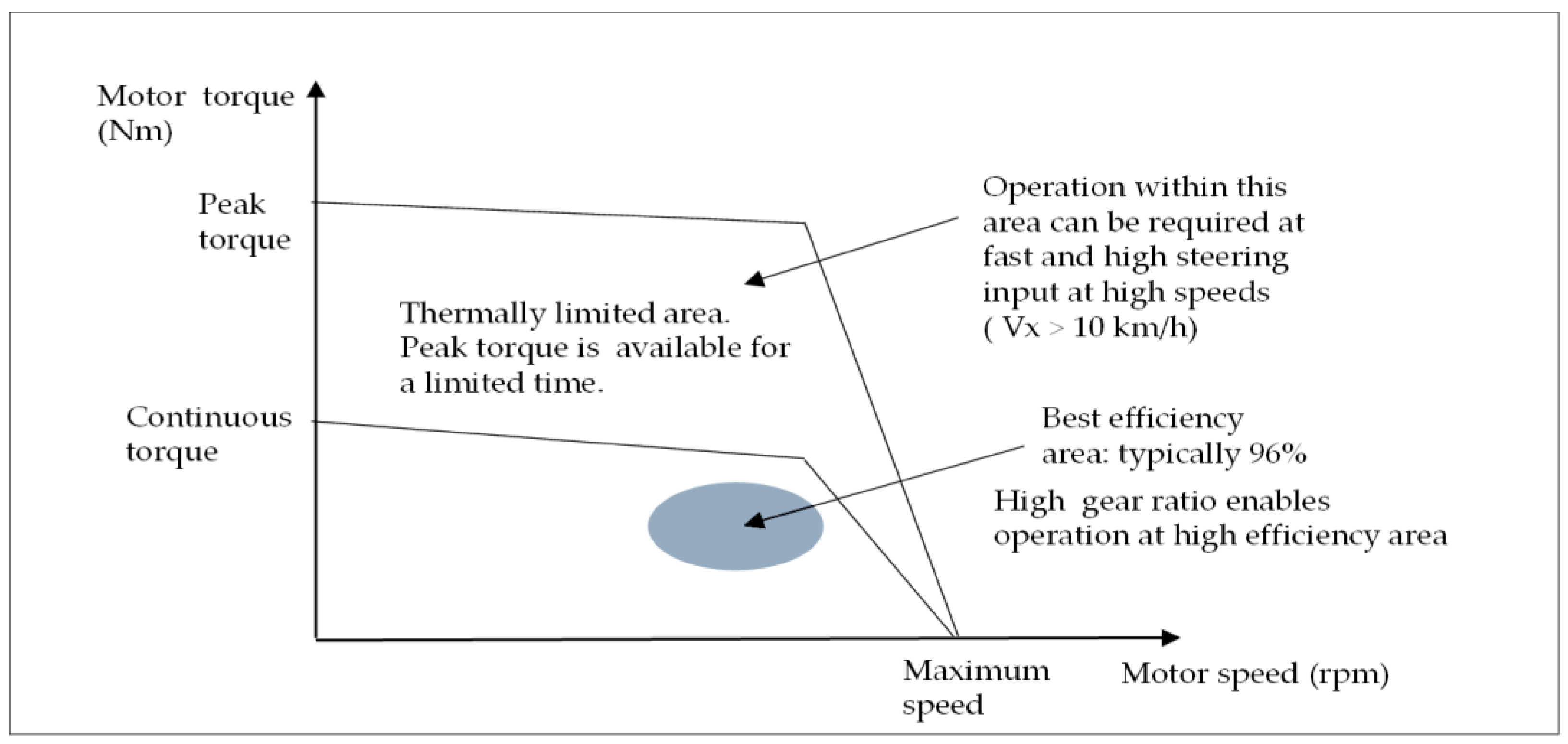
Limited duration of operation at maximum peak torque which is typically between 0 and 5 s. Duration of operation between continuous torque and maximum peak torque curves varies depending on the motor thermal condition as shown in Figure 2. This constraint is the most critical one when operating at high vehicle speeds above 10 km/h. Therefore, reduction of peak torque is the most critical design criteria. If servo motor can be coupled with a gearbox having high gear ratio, operation within the thermally limited area can be avoided.

1.3.1. Comparison of Hydraulic and Servo Motor Actuators

Comparison of electric and hydraulic actuators is given in [33]. The following comparison is given for active tilt control applications.
Advantages of hydraulic actuator:
  • Dual actuator topology for right and left suspensions can be easily integrated;
  • Fewer parameters and simple operation for integration;
  • High damping provides higher comfort during tilting motion.
Disadvantages of hydraulic actuator:
  • Less efficiency;
  • Slow torque dynamics;
  • Gearbox cannot be used as applied in servo motor, which increases hydraulic actuator torque rating;
  • Internal speed control loop is not a standard loop for hydraulic actuators;
  • More components;
  • More audible noise;
  • Low temperature causes increase of viscosity, which causes vibration, noise, and wear of internal pump parts;
  • Performance variation at high and low temperatures.
Advantages of servo motor actuator:
  • Torque linearity within defined temperature limits (typically between 0 and 40 degrees);
  • Fast torque response can compensate for system delays in the DTC method;
  • Fewer moving components;
  • Minimum maintenance;
  • Monitoring capability of motor and MCU parameters such as estimated torque, power and temperature etc;
  • High system efficiency >85%;
  • High accuracy of positioning and speed control;
  • Enabling configuration of motor control parameters such as tuning of speed, position control loops, ramp profiles (linear, S-ramp to reduce jerk), torque monitoring and limitation;
  • Electrically safe operation up to 60 V DC;
  • Electrical motor can be coupled with required gearbox to increase tilt torque.
Disadvantages of servo motor actuator:
  • Less damping than hydraulic actuator;
  • Limited duration of operation at peak torque due to thermal limit of electric motors;
  • Torque derating above 40°.

2. Application Methodology

In following sections, selection of servo motor control modes, interaction between tilt control system and servo motor actuator, and proposed control loop configuration are described. This section can be considered as the conceptual development phase.
In this study, a three-phase permanent magnet synchronous servo motor and motor control unit are used as the actuator owing to its advantages listed in Section 1.3.1.
Important specifications of the servo motor actuator for a tilt control system are listed below.
  • 24 or 48 V battery supply for servo motor controller;
  • Operating the motor at efficient points;
  • Ratio of load to motor inertia and selection of gear ratio of gearbox as design parameter;
  • Duty cycle and requested maximum torque should match with servo motor torque-speed curve shown in Figure 2.
  • PM motors have a cogging torque problem that affects the tilting comfort and also can cause positioning errors [34]. In the case of using a gearbox with high gear ratio, cogging torque is amplified and may cause discomfort at the driver side and vibration through the vehicle body. Therefore, the servo motor should have minimum cogging torque.

2.1. Selection of Control Mode of Servo Motor Controller

Tilt control configuration depends on the selection of control mode of the servo motor. There are three control modes as described below, which are torque, speed, and position control modes. Based on the descriptions given below, the position control mode is selected for the servo motor controller (SMC) used in this study. Controller update time of servo motor controller given below is typical; servo control loops are studied in detail in [32,35].
  • Current controller: 62.5…125 µs;
  • Speed controller: 62.5…500 µs;
  • Position controller: 500 µs…4 ms;
These update times should be considered when defining the tilt controller update time for software development and the discrete form of the tilt controller as well.The control modes of a SMC are described briefly as below regarding their applicability in tilt control.

2.1.1. Torque Control Mode

If torque mode is set for any motor controller, speed depends on the load applied to the motor. The motor speed will increase very fast at torque mode at no-load condition. In general, for a safe operation, the motor should be started always at load if the motor controller is set to torque mode. Considering the variation of lateral acceleration, torque mode is not a safe mode for the tilt control system. It can be used only if it is cascaded by an outer control loop such as speed and position loop so that the torque control loop output is limited. System safety depends on reliable operation of the tilt control loop.

2.1.2. Speed Control Mode

If the SMC is set in speed mode and tilt controller set in position mode as upper level (outer loop) controller, the vehicle is in severe danger in the case of failure of the tilt control loop. The vehicle will rotate and fall down because the servo motor will continuously rotate as it is set to speed mode. The control algorithm should include a failure mode and limitations for this configuration.

2.1.3. Position Control Mode

The SMC can be set in position control mode and the tilt controller can be integrated as a secondary position controller as shown in Figure 3. The tilt position reference is calculated by using the tilt position measured by inertial measurement units (IMU).
Position control mode can help to minimize the control mode changeover problems if an NTV combines both DTC and STC methods. In this way, the position actual values can be matched easily for DTC and STC actuators. This can provide an easier changeover between DTC and STC actuators.

2.2. Interactions between Tilt System and Servo Motor Actuator

During tilting motion, the following interactions exist between lateral vehicle dynamics and load reflected at the servo motor shaft. This interactions should be considered when designing a tilt controller
  • There are transient and steady-state components of lateral acceleration, as given in Equation (1) [11].
In case the tilt controller type is a PD controller and the tilt position reference includes the lateral translation acceleration y ¨ as given in (1) [11], the vehicle can be exposed to undesirable vibrations during tilting. Because noise and peaks in the measurement of lateral translation acceleration cause undesired vibrations, an undesired activation of actuator occurs as well. The problem can be even worse if the SMC is tuned to respond faster, i.e., hard tuned.
θ t i l t _ r e f = y ¨ + ψ ˙ V x g
2.
In order to produce a tilt control reference, reliable and practically realizable methods and signals are required for stable operation. Lateral translation acceleration y ¨ is used in PD control [1,11], and lateral vehicle speed y ˙ is used as a state variable in state feedback by H2 optimal control in [16]. Both of these variables are difficult to measure or estimate in a reliable manner. In order to produce faster torque response without using y ¨ or y ˙ , an alternative method is proposed in Section 3.1.5.
3.
Actuator dynamics and low stiffness of tilting system: Very fast actuator response can cause oscillations during tilting because suspension and tire elasticity exhibit a flexible system with low rigidity. Although the fast torque response is desired to reduce the perceived acceleration, the actuator should not cause oscillations through the tire suspension system. A similar problem occurs in electric vehicles, which is known as electric drive-train oscillations [36].
4.
Ratio of load to motor inertia: The roll inertia of NTV about the roll axis can be around 80 kg∙m2 range [11,16]. In case the three wheeled vehicle is used for logistic applications, it can have additional payload, and hence roll (tilt) inertia will increase further. Servo motor in this study has 0. 34 kg∙cm2 rotor inertia [37]. In servo motor applications, there is a limitation for the load-to-motor inertia ratio [38]. The most practical way of providing the limitation is to use a gearbox.

2.3. Definition of Servo Motor Operating Points and Actuator Gear Ratio

Assuming the same shaft power, torque-speed curve of servo motor can be defined in two ways:
  • A servo motor with higher torque and lower speed range: This type of servo motor requires a lower gearbox ratio. Large motor diameter is the main concern. Efficient operating points may not be provided at low speeds.
  • A servo motor with lower torque and higher speed range: This type of servo motor requires a gearbox with higher gear ratio. The motor can be operated at higher speed and hence at higher efficiency area.
In this study, the second type of servo motor is selected because, it enables reduction in diameter and operation at high efficiency area as shown in Figure 2. These arguments are also applied in development of electric vehicle powertrain by two speed or multi-speed transmissions [39,40].
Since the total load inertia reflected at the motor shaft is decreased by the inverse square of the gear ratio, a gearbox with higher gear ratio reduces the roll inertia reflected at the actuator motor shaft. In this way, changes in the roll inertia have minor effect on the servo motor control loops.

2.4. Prototype Vehicle Configuration and Proposed Control Configuration

2.4.1. Vehicle Configuration

The specifications of the vehicle are given below. These data are used in the simulations and vehicle tests.
  • Three-wheeled electric NTV, one front wheel and two rear wheels as shown in Figure 4;
  • Maximum steering angle 45 degrees;
  • Traction system has an electric motor and Li-ion battery at 48 V DC;
  • Tilt actuator system and control modules are supplied by separate 24 V DC;
  • Tilt actuator system has separate system control unit.

2.4.2. DTC Mechanism and Actuator Layout

In [24], three possible vehicle configurations for tilting are given, which are single body tilting type, chassis tilting type, and body separation tilting type vehicles. Among these configurations, the tilting mechanism implemented in this paper is the chassis tilting type.

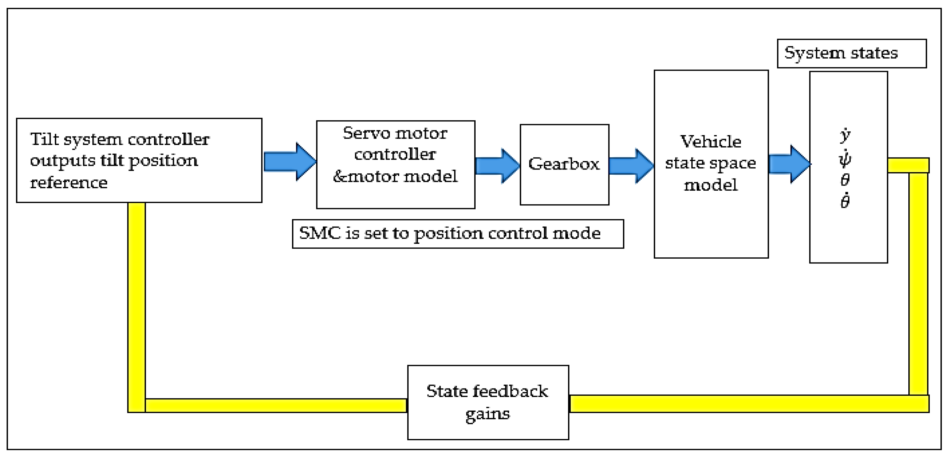
2.4.3. Proposed Control Loop Configuration

Control configuration including the tilt controller is shown in Figure 5. In the proposed control configuration, the state feedback controller produces the tilt position reference and software is implemented in a system control unit (SCU). The servo motor controller (SMC) is set in position control mode to track the tilt position reference. A distinctive feature of this configuration is that the tilt position feedback used for state feedback control is measured by an inertial measurement unit (IMU) mounted on the tilting axis of the NTV. In this way, the vehicle position can be directly measured considering the limitations on tilting angle, which are critical for safety. A second advantage is that the position feedback from the tilting axis includes the tilting dynamics effects such as tire and suspension elasticity and compliances acting on the tilting mechanism, which cannot be accurately measured by the position encoder mounted on the motor shaft.
In the case the motor and load have different motion axis and the load has nonlinear effects such as compliance and gear backlash, measurement on the load side encoder is recommended in motion control applications for accurate position control [32,41,42]. For this kind of special motion control application, a double position control loop is proposed in [41].
In the proposed control loop configuration, a double position loop is implemented. The outer position loop is the tilt control loop, which is running based on system states. The inner position loop is the control loop running in SMC.
For the system controller unit (SCU), a vehicle control unit (VCU) is used available in [43].

3. Design and Simulation

3.1. Controller Design

3.1.1. Mathematical Model of a Three-Wheeled Vehicle

State space equations for a three-wheeled vehicle given in [16] are used in this study, where system states are lateral speed, yaw rate, roll angle, and roll speed. Compared to the state space model given in [4], the state space model in [16] is arranged for constant Vx for linear controller design. This model is developed for two front wheels and two rear wheels. Therefore, a coefficient of 2 is applied to C f C r and λ f λ r , a and b terms in Equation (2) [16]. The vehicle in this study has one front wheel and two rear wheels. Therefore, in order to use the same mathematical model, the coefficient of 2 is multiplied by 0.5 for the front wheel terms as indicated by coefficient k f in the nomenclature.
In this model, a linear tire model is used, i.e., tire slip angle is ignored. The model is valid under the assumption that Vx > 0.
State space equations of tilt control are given in (2).
X ˙ ( t ) = A X ( t ) + B u ( t )
Elements of matrix A in (2) are given as below:
A = [ a 11 a 12 a 13 a 14 a 21 a 22 a 23 a 24 a 31 a 32 a 33 a 34 a 41 a 42 a 43 a 44 ] a 11 = ( a m V x h 2 a I x V x ) ,   a 12 = ( b m V x V x h 2 b I x V x ) , a 13 = 2 ( λ f + λ r ) ( 1 m + h 2 I x ) m g h 2 I x   ,   a 14 = 0 a 21 = ( b I z V x ) , a 22 = ( 2 ( C f l f 2 + C r l r 2 ) I z V x )   , a 23 =   2 ( λ f l f λ r l r ) I z ,   a 24 = 0 a 31 = 0 ,   a 32 = 0 ,   a 33 = 0 ,   a 34 = 1 a 41 = ( h a I x V x ) ,   a 42 =   ( h b   I x V x )   , a 43 =   m g h 2 h ( λ f + λ r ) I x , a 44 = 0
System states matrix X(t), matrix B and control input u(t) in (2) are given as below:
X ( t ) = [ y ˙ ψ ˙ θ θ ˙ ] ,   B = [   B δ B T ] ,   B δ = [ 2 C f ( 1 m + h 2 I x ) 2 C f l f I z 0 2 C f h I x ] ,   B T = [ h I x 0 0 1 I x ] u = [ δ T t i l t ]

3.1.2. Controllability and Observability

In order to apply the state feedback control by pole placement design, the system should be fully state controllable. Since an observer is not used in the proposed control method, and measured data are used instead, only controllability criteria given in [44] are applied, as given below:
Controllability matrix Ccont was calculated in Matlab and its rank yields 4. As matrix A is a 4 × 4 matrix, the system is fully state controllable.
C c o n t = [ B   A B   A 2 B   A 3 B ] Rank ( C c o n t ) = 4

3.1.3. Pole Placement Design Considering Minimum Input Power

Pole placement design is described in detail in [44]. Control properties and advantages of the state feedback applied in this study are described as follows:
  • Steady state power should be constant or zero in a perfectly coordinated turn. This property of tilt control can also be interpreted by the stability law of the Lyapunov’s direct method which states that zero energy consumed by a mechanical system corresponds to an equilibrium state whereas instability is related to continuously increasing mechanical energy [45].
  • As shown in simulations, the yaw rate and tilt angle feedback terms perform a rampwise action similar to integral action that ramps the actual value to the control reference [46]. Therefore, the actuator control model has no need for an integrator. In most state-of-art studies, a proportional derivative controller is used.
  • Tilting speed is the derivative of the tilting position and its effect as a state feedback is similar to the derivative term in PD control.
  • Gain applied to lateral speed is set to zero. This is due to the complexity of estimation of lateral speed and variation in estimation error. The requested stability can also be provided by ignoring it. Lateral speed and yaw rate have similar changes. Detailed simulations are given in [16]. Moreover, estimation error and noise of lateral speed can yield inaccurate results which can risk the stability in practical experiments. Proper settings of gains applied to yaw rate, tilt position and speed can compensate for the absence of lateral speed feedback. Lateral speed estimation methods and simulation results are studied in [47].

3.1.4. Simplified Model of Servo Motor Controller and Control Input

A mathematical model of a field oriented controlled surface mounted permanent magnet synchronous motor (PMSM) is given in [48,49] is applied to obtain the simulation results in Section 3.2.
In order to simplify the analysis given below, it is assumed that the servo motor actuator has a first order system response [32,50].
By assuming a stiff connection between the servo motor shaft and gearbox, and ignoring the friction, the basic equation of motion of an electric motor is given in (4):
T m = I t o t θ ¨ s m + T l o a d  
The total inertia reflected on the servo motor shaft is given in (5)) and reduced by the inverse square of the gear ratio Kg:
I t o t = I x K g 2 + I m  
Output of the position controller is the speed reference and output of the speed controller is the torque reference [32,48]. Servo motor control loops and simplified models are analysed in [32]. Current controller dynamics is in range of µs, as described in Section 2.1, and therefore not included here.
To express the actuator torque input in (2) in a simple form, a proportional controller is assumed for position and speed controller of the SMC. Total gain of the servo control loop is proportional with the load-to-motor inertia ratio [46].
Speed reference of the SMC is the output of the position controller and given as:
θ ˙ s m _ r e f = [ K p o s ( θ s m r e f θ s m ) ]  
Output of the speed controller in a field-oriented controlled PMSM motor can be either torque producing current Isq or torque reference [48].
In this analysis, output of the speed controller of SMC is defined as torque reference of SMC and given as:
T s m _ r e f = K s p [ θ ˙ s m _ r e f   θ ˙ s m   ]  
Output of the state feedback controller is given as product of state feedback gain matrix K and system state matrix X(t):
θ t i l t _ r e f = [ K y ˙   K ψ ˙   K θ   K θ ˙ ] [ y ˙ ψ ˙ θ θ ˙ ]  
By using the Equations (6)–(8), Equation (9) is obtained including the simplified control loops of the SMC and gear ratio. State feedback gain for yaw rate,   K ψ ˙ is scaled dependent on the actual vehicle speed V x .
T t i l t = K g ( K s p K p o s K ψ ˙ ψ ˙ + K s p K p o s ( K θ 1 ) θ + ( K s p K p o s K θ ˙ K s p ) θ ˙ )  
Equation (9) is used in (2) as the actuator torque input to obtain the form given in (10) [43]. Based on this analysis, the closed loop poles are located as given in Table 1.
u = −KX
To achieve minimum perceived lateral acceleration and minimum actuator torque at steady state, the closed loop poles are located as shown in Table 1. Closed loop pole locations and gains are set based on tests in the simulations to obtain minimum actuator torque and perceived acceleration.
Target speed range in the simulation study is 8 m/s. It can be concluded from Table 1 that the tilt control system has slower response as the speed increases and hence higher actuator torque is needed for stability.

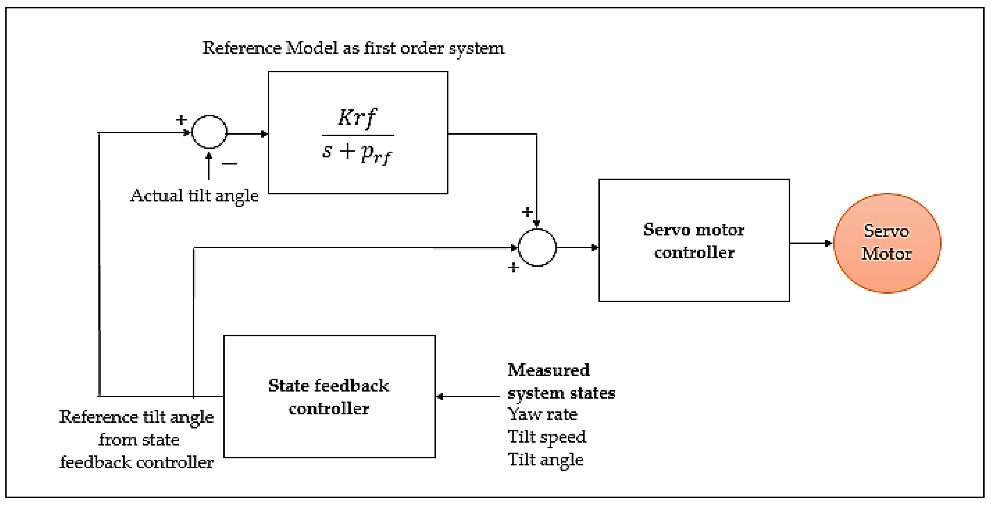
3.1.5. Improvement of State Feedback Control with Reference Model Concept

The reference model (RM) concept proposed here provides faster torque response and hence reduction of perceived acceleration and peak actuator torque as shown in simulations. In [32], an application of RM is given for a PI controller.
In the proposed tilt control configuration, RM has no effect during steady state. It can be interpreted as an acceleration support function and easily combined with the tilt control loop to control the servo motor controller as shown in Figure 6. Another advantage is that RM can speed the torque response without increasing the gains of SMC. It can be combined with a tilt controller that should provide the stabilization.
Krf is the gain of RM and prf is the pole of RM that can be selected based on desired torque response. In [51], PID control with model-based feed-forward compensation is studied, which is similar to RM concept.

3.2. Simulation

In the Simulink model, in order to simulate the motor phase current, torque and power, a complete PMSM model with field-oriented control is used in combination with the state space model given in (3) and state feedback controller.
A PMSM servo motor with 400 W rated power at 3000 rpm, 1.3 Nm continuous torque, and 3.8 Nm peak torque is used as the motor data in the simulation model and experiments. The integrated motor inverter is JVL servo motor MAC 402 [37]. Simulation is run using the datasheet in [37] as the reference motor data. In simulations in Section 3.2.1 and experiments in Section 4, a gearbox with 330:1 ratio is used to increase the servo motor torque.

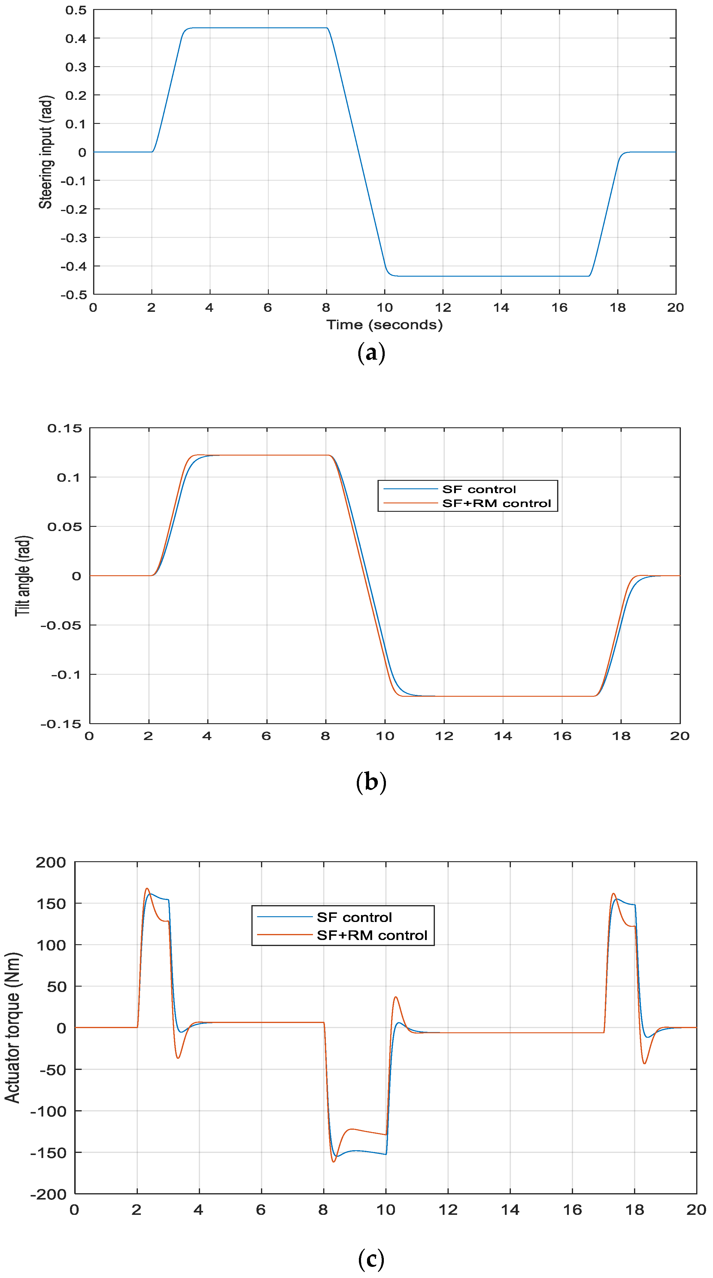
3.2.1. Simulation Results

Simulations results are given at 2 m/s and 8 m/s longitudinal vehicle speeds. The actuator torque given in simulations refers to the torque at the output of the gearbox coupled to the servo motor. To calculate battery power consumption, 96% SMC efficiency and 90% gearbox efficiency is assumed. At 2 m/s vehicle speed, servo motor efficiency is assumed as 85%, and at 8 m/s vehicle speed it is assumed as 90%. Efficiency data of the components in the prototype vehicle are not available. Therefore, the given efficiency data can be considered as an approximation. Controller parameters in simulation are given in Table 2.
Perceived acceleration in simulation is calculated as given in (11) [18]:
a p e r = ( y ¨ + V x ψ ˙ ) c o s   θ + h θ ¨ g s i n   θ
Case (1): Turning a corner at 2 m/s and 25 degrees steering input
The steering input angle applied by the vehicle driver changes within 1 s from zero to 25 degrees at t = 2 s. At t = 10 s, it changes from 25 degrees to −25 degrees within 2 s.
Peak torque with state feedback alone is 162 Nm. When combined with RM control, the duration of peak torque is lower with the reference model. It is reduced from 166 to 127 Nm within 0.7 s. This is a critical benefit for the servo motor, because permissible operation time at peak torque is limited as shown in Figure 2.
The peak value of perceived acceleration is 0.80 m/s2 with state feedback control. Perceived acceleration is reduced from an initial value of 0.77 to 0.67 m/s2 with state feedback control and reference model combination. Further reductions in peak torque and perceived acceleration can be obtained. However, undershoot of torque and perceived acceleration is increasing as the gain of the reference model is increasing.
Case (2): Turning a corner at 8 m/s and 5 degrees steering input
In this test, the steering angle changes within 1 s from zero to 5 degrees and then at t = 10 s, it changes from 5 degrees to −5 degrees within 2 s.
As shown, state feedback control with a linearized model cannot yield a perfect coordinated turn at high vehicle speeds. Therefore, the actuator torque and perceived acceleration cannot be zero at the same time. Thus, there must be minimum level of actuator torque to minimize the perceived acceleration as can be seen in the curves.
Perceived acceleration is 1.23 m/s2 in state feedback control; when combined with the reference model, it can be reduced to 1.05 m/s2. The actuator torque is 248 Nm in state feedback control. When it is combined with reference model control, actuator torque peak value is initially 223 Nm and reduced to 200 Nm within 0.4 s.
As can be seen in Figure 7 and Figure 8, if the actuator torque is overdamped, i.e., if overshoot and undershoot are minimized, higher perceived acceleration occurs. Therefore, slightly overshooted and undershooted torque with faster response can reduce the perceived acceleration better than overdamped torque response.
In simulations, the servo motor torque at the gearbox input is kept below its continuous value, which is 1.3 Nm. In case 2, the maximum peak torque at the servo motor shaft is 0.75 Nm. Energy consumption at the end of tilting cycle is 24.3 Ws with state feedback and RM control combination.
Servo motor in tilt control applications should operate with natural cooling because liquid cooling is not feasible in terms of space, extra cost, and energy consumption. It should also operate in all weather conditions.
As described in Section 1.3 and depicted in Figure 2, there is time limited operation in thermally limited area of servo motor torque-speed curve. Depending on the driving conditions, automatic power-derating or current limit function of SMC can be activated if the servo motor should operate within this area longer than the permissible time. In such a case, requested tilt torque cannot be provided by the servo motor because of the auto-derating of SMC. This kind of interaction between tilt controller and SMC can cause an instability or sudden increase of perceived acceleration. If the drive cycle of the vehicle with a tilting cycle could be estimated, sizing of motor torque could be optimized further. However, every driver has a different drive style. As a conclusion, it is critical not to exceed the continuous torque and thermal limits of the motor so that motor can produce the requested torque for the next tilting motion. This is achieved in the given simulation test cases.

4. Experimental Results

4.1. Software Development

The tilt controller is implemented on Ecotrons VCU 2274A (vehicle control unit) used in electric vehicles as a system controller [43]. Models developed in Simulink can be embedded into Ecotrons VCU by using its code generation tool. Low complexity of the state feedback controller enables practical software development and code generation as well.
VCU has CAN 2.0 protocol and SMC has Profinet protocol. The communication interface between VCU and SMC is implemented using protocol converter from CAN 2.0 to Profinet. The same conversion is implemented between the VCU and IMU sensor, which has a CANopen interface. The main steps of software development follow:
Software in SCU:
Software development in SCU based on Simulink models;
Creation of CAN 2.0 .dbc files for CAN messages;
Code generation in SCU.
Software in PLC and gateway modules:
PLC program development for protocol conversions and matching of messages;
Configuration of gateway modules for each CAN message;
Protocol conversion for SMC is implemented from Profinet to CAN 2.0;
Protocol conversion for absolute encoder measuring the steering position is implemented from Profinet to CAN 2.0;
For IMU sensor: from CANopen to Profinet and from Profinet to CAN 2.0.
Tilt controller models in VCU are updated with 5 ms update rate. This is a realistic update time considering the typical controller update times of SMC servo motor control given in Section 2.1.

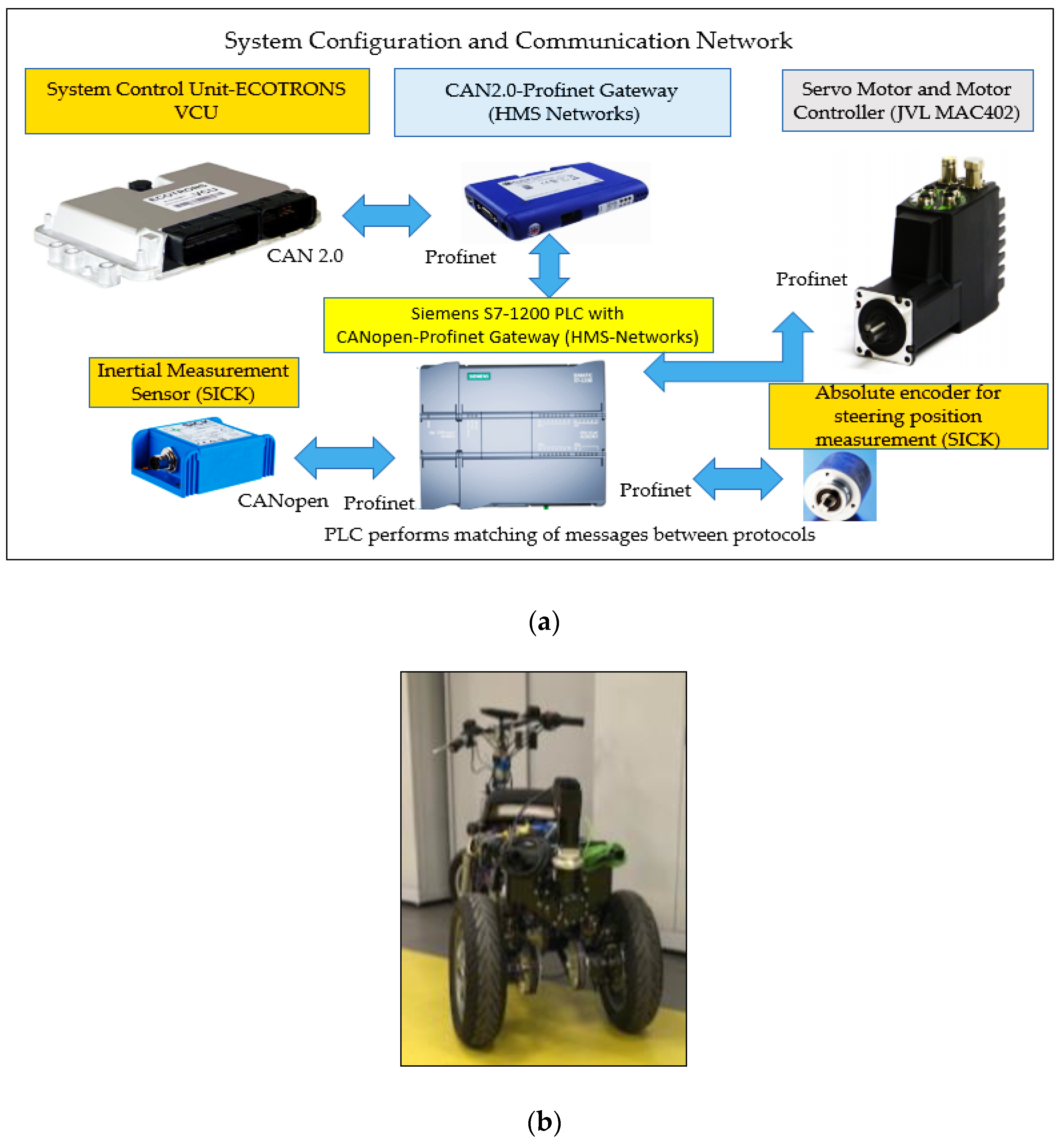
4.2. Configuration of Test Equipments

The servo motor and control modules shown in Figure 9a are supplied by a 24 V battery. The servo motor can provide its rated torque at 24 V as well. The components of tilt control are shown in Figure 9. (The figures of the components are sourced from and available in [37,43,52,53,54]).

4.3. Experiments

Experimental results were performed by using the components and prototype three wheeled electric vehicle shown in Figure 9a,b. The cornering test was performed at 2 m/s vehicle speed Results of cornering tests are given in Figure 10.
The second test was performed at 1.3 m/s speed and the driver applied random slalom test by moving the vehicle from left to right directions. This scenario can happen in city traffic while changing lanes rapidly. The results of slalom tests are given in Figure 11. It was validated in both tests that state feedback controller and tilt control system developed can maintain the stability by tilting the vehicle.
All data given in Figure 10 and Figure 11 are logged by SCU, i.e. by vehicle control unit, during the tests. SCU runs the tilt control software for the duration of the whole test. SMC transmits the estimated motor torque signal via Profinet interface. Actuator torque data given in Figure 10 and Figure 11 are obtained by logging the estimated torque signal multiplied by the gear ratio of gearbox.

4.3.1. Cornering Test at 2 m/s Vehicle Speed

Vehicle speed is constant in the simulations. However, this is not realistic in actual driving conditions. Because, the driver can change the vehicle speed in real traffic conditions.
The actuator is activated for the duration of test for safety and to evaluate its performance. Vehicle speed is increased up to 2 m/s and kept almost constant at the time of cornering and reduced to zero after the cornering is completed.
The steering input by the vehicle driver reaches a maximum of 28 degrees, as measured by the steering angle sensor. Peak of servo motor torque is 0.177 Nm.

4.3.2. Slalom Test

A slalom test was performed to test the tilt control system in left and right turn maneuvers. Maximum vehicle speed is 1.3 m/s in slalom tests.
In experimental tests, stability of the tilt control system is validated for the given test cases. In both test cases, the maximum lateral translation acceleration (LTA) and maximum actuator torque occur approximately at the same time. LTA is not included in the controller because of its high noise content. However, the synchronization between the peak of LTA and peak torque of the actuator also indicates that the controller performs as expected. Change of the tilt angle is also in synchronized with the steering input.
Tests were performed at low speeds for the safety of the vehicle driver.

5. Conclusions

In this study, a tilt control system was developed, including the steps of controller design, actuator application, software development, and integration into a three wheeled electric vehicle. It was demonstrated that development of tilt control system is a more comprehensive task than designing the tilt controller itself.
It is crucial that the tilt controller should work stable in an embedded software and hardware platform where the system controller has an interface with the actuator controller, communication gateway modules and IMU sensor. The second critical issue is the nonlinearity of vehicle lateral dynamics which can be different for each three wheeled vehicle. This is a common issue where simulation results can deviate from actual implementation.
Some of the critical future tasks can be listed, such as energy management of tilt control should be coordinated with energy management of the electric vehicle. Fail safe algorithms should be developed in case the actuator or IMU sensor fails.

Author Contributions

Conceptualization, M.K. and O.B.A.; methodology, M.K.; software, M.K.; validation, M.K.; formal analysis, M.K. and O.B.A.; writing—original draft preparation, M.K.; writing—review and editing, M.K. and O.B.A.; supervision, O.B.A. All authors have read and agreed to the published version of the manuscript.

Funding

This research received no external funding.

Institutional Review Board Statement

Not applicable.

Informed Consent Statement

Not applicable.

Data Availability Statement

Not applicable.

Acknowledgments

Authors thanks Ford Otosan A.S. for financial support and providing the laboratory equipments for the project.

Conflicts of Interest

The authors declare no conflict of interest.

Nomenclature

θtilt_refTilt control reference (rad)
AState matrix in state space equation
BInput matrix in state space equation
B δ Input matrix for steering input
B T Input matrix for actuator torque input
m Total vehicle mass including driver (290 kg)
V x Longitudinal vehicle speed (m/s)
h Height of center of gravity (0.65 m)
k w h Coefficient representing one front wheel in Equation (2) (0.5)
λf1Front wheel camber stiffness (1500 N/rad)
λ f = λ f 1 k w h Front wheel camber stiffness applied in Equation (2) (750 N/rad)
λrRear wheel camber stiffness (1000 N/rad)
C f 1 Front wheel cornering stiffness (8000 N/rad)
C f = C f 1 k w h Front wheel cornering stiffness applied in Equation (2) (4000 N/rad)
C r Rear wheel cornering stiffness (10.000 N/rad)
lfDistance from center of gravity to front wheel (0.65 m)
l r Distance from center of gravity to rear wheels (0.75 m)
a = 2 ( C f + C r )
b = 2 ( C f l f C r l r )
IxTilt moment of inertia (75 kg∙m2)
I z Yaw moment of inertia (140 kg∙m2)
gGravity of earth (9.81 m/s2)
y ˙ Lateral speed of vehicle (m/s)
y ¨ Lateral translation acceleration of vehicle (m/s2)
ψ ˙ Yaw rate (rad/s)
θ Actual tilt angle (rad)
θ ˙ Actual tilt speed (rad/s)
δ Driver steering input (rad)
T t i l t Tilt actuator torque (Nm)
θsmrefPosition reference of SMC (rad)
θ s m Actual position of SMC (rad)
θ ˙ s m _ r e f Speed reference of SMC (rad/s)
θ ˙ s m Speed actual value of SMC (rad/s)
T s m _ r e f SMC torque reference (Nm)
I t o t Total moment of inertia reflected on servo motor shaft (kg∙m2)
I m Moment of inertia of servo motor (kg∙m2)
K g Gear ratio of gearbox (330:1)
K p o s Position controller gain of SMC
K s p Speed controller gain of SMC
K y ˙   State feedback gain of lateral speed
K ψ ˙ State feedback gain of yaw rate
K θ   State feedback gain of tilt angle
K θ ˙ State feedback gain of tilt speed
K r f Gain of reference model
prfPole of reference model
a p e r Perceived acceleration (m/s2)

References

  1. So, S.-G.; Karnopp, D. Active Dual Mode Tilt Control for Narrow Ground Vehicles. Veh. Syst. Dyn. 1997, 27, 19–36. [Google Scholar] [CrossRef]
  2. So, S.-G.; Karnopp, D. Switching Strategies for Narrow Ground Vehicles with Dual Mode Automatic Tilt Control. Int. J. Veh. Des. 1997, 18, 518–532. [Google Scholar]
  3. Gohl, J.; Rajamani, R.; Alexander, L.; Starr, P. The Development of Tilt-Controlled Narrow Ground Vehicles. In Proceedings of the American Control Conference, Anchorage, AK, USA, 8–10 May 2002. [Google Scholar]
  4. Rajamani, R.; Gohl, J.; Alexander, L.; Starr, P. Dynamics of narrow tilting vehicles. Math. Comput. Model. Dyn. Syst. 2003, 9, 209–231. [Google Scholar] [CrossRef]
  5. Gohl, J.; Rajamani, R.; Alexander, L.; Starr, P. Active Roll Mode Control Implementation on a Narrow Tilting Vehicle. Veh. Syst. Dyn. 2004, 42, 347–372. [Google Scholar] [CrossRef]
  6. Piyabongkarn, D.; Keviczky, T.; Rajamani, R. Active Direct Tilt Control For Stability Enhancement Of A Narrow Commuter Vehicle. Int. J. Automot. Technol. 2004, 5, 77–88. [Google Scholar]
  7. Drew, B.W. Development of Active Tilt Control for a Three-Wheeled Vehicle. Ph.D. Thesis, University of Bath, Bath, UK, 2006. [Google Scholar]
  8. Snell, A. An Active Roll-Moment Control Strategy for Narrow Tilting Commuter Vehicles. Veh. Syst. Dyn. 1998, 29, 277–307. [Google Scholar] [CrossRef]
  9. Kidane, S.; Alexander, L.; Rajamani, R.; Starr, P.; Donath, M. A fundamental investigation of tilt control systems for narrow commuter vehicles. Veh. Syst. Dyn. Int. J. Veh. Mech. Mobil. 2008, 46, 295–322. [Google Scholar] [CrossRef]
  10. Chiou, J.C.; Lin, C.Y.; Chen, C.L.; Chien, C.P. Tilting motion control in narrow tilting vehicle using double-loop PID controller. In Proceedings of the 7th Asian Control Conference, Hong Kong, China, 27–29 August 2009. [Google Scholar]
  11. Kidane, S.; Rajamani, R.; Alexander, L.; Starr, P.; Donath, M. Development and experimental evaluation of a tilt stability control system for narrow commuter Vehicles. IEEE Trans. Control. Syst. Technol. 2010, 18, 1266–1279. [Google Scholar] [CrossRef]
  12. Berote, J. Dynamics and Control of a Tilting Three Wheeled Vehicle. Ph.D. Thesis, University of Bath, Bath, UK, 2010. [Google Scholar]
  13. Cabrera, L.D.S. Active Tilt and Steer Control for a Narrow Tilting Vehicle. Ph.D. Thesis, Politecnico di Torino, Torino, Italy, 2010. [Google Scholar]
  14. Poelgeest, A.V. The Dynamics and Control of a Three-Wheeled Tilting Vehicle. Ph.D. Thesis, University of Bath, Bath, UK, 2011. [Google Scholar]
  15. Mourad, L.; Claveau, F.; Chevrel, P. A Lateral Control Strategy for Narrow Tilting Commuter Vehicle Based on the Perceived Lateral Acceleration. In Proceedings of the 18th World Congress The International Federation of Automatic Control, Milano, Italy, 28 August–2 September 2011. [Google Scholar]
  16. Mourad, L. Contrôle actif de l’accélération latérale perçue d’un véhicule automobile étroit et inclinable. In Automatique/Robotique; Ecole des Mines de Nantes: Nantes, France, 2012. [Google Scholar]
  17. Robertson, J. Active Control of Narrow Tilting Vehicle Dynamics. Ph.D. Thesis, University of Bath, Bath, UK, 2014. [Google Scholar]
  18. Claveau, F.; Chevrel, P.; Mourad, L. Non-linear control of a narrow vehicles, tilting vehicle. In Proceedings of the 2014 IEEE International Conference on Systems, Man, and Cybernetics, San Diego, CA, USA, 5–8 October 2014. [Google Scholar]
  19. Mourad, L.; Claveau, F.; Chevrel, P. Direct and Steering Tilt Robust Control of Narrow Vehicles. IEEE Trans. Intell. Transp. Syst. 2014, 15, 1206–1215. [Google Scholar] [CrossRef] [Green Version]
  20. Sindha, J.; Chakraborty, B.; Chakravarty, D. Automatic stability control of three-wheeler vehicles-recent developments and concerns towards a sustainable technology. Proc. Inst. Mech. Eng. Part D J. Automob. Eng. 2018, 232, 418–434. [Google Scholar] [CrossRef]
  21. Furuichi, H.; Huang, J.; Fukuda, T. Switching dynamic modelling and driving stability analysis of three-wheeled narrow tilting vehicle. IEEE/ASME Trans. Mechatron. 2014, 19, 1309–1322. [Google Scholar] [CrossRef]
  22. Ataei, M. Reconfigurable Integrated Control for Urban Vehicles with Different Types of Control Actuation. Ph.D. Thesis, University of Waterloo, Waterloo, ON, Canada, 2017. [Google Scholar]
  23. Ren, Y.; Dinh, T.Q.; Marco, J.; Greenwood, D.; Hessar, C. Nonlinearity Compensation based Tilting Controller for Electric Narrow Tilting Vehicles. In Proceedings of the 5th International Conference on Control, Decision and Information Technologies (CoDIT’18), Thessaloniki, Greece, 10–13 April 2018. [Google Scholar]
  24. Tang, C. Narrow Urban Vehicles with an Integrated Suspension Tilting System. Design, Modeling, and Control. Ph.D. Thesis, University of Waterloo, Waterloo, ON, Canada, 2018. [Google Scholar]
  25. Docquier, Q. Dynamic Analysis and Control of Narrow Track Vehicles via a Multibody Modeling Approach. Ph.D. Thesis, Catholique University of Leuven, Ottignies-Louvain-la-Neuve, Belgium, 2020. [Google Scholar]
  26. Nguyen, A.T.; Chevrel, P.; Claveau, F. LPV Static Output Feedback for Constrained Direct Tilt Control of Narrow Tilting Vehicles. IEEE Trans. Control. Syst. Technol. 2018, 28, 661–670. [Google Scholar] [CrossRef]
  27. Choi, Y.; Lee, W.; Kim, J.; Yoo, J. A Variable-Sampling Time Model Predictive Control Algorithm for Improving Path-Tracking Performance of a Vehicle. Sensors 2021, 21, 6845. [Google Scholar] [CrossRef] [PubMed]
  28. Rohten, J.A.; Muñoz, J.E.; Pulido, E.S.; Silva, J.J.; Villarroel, F.A.; Espinoza, J.R. Very Low Sampling Frequency Model Predictive Control for Power Converters in the Medium and High-Power Range Applications. Energies 2021, 14, 199. [Google Scholar] [CrossRef]
  29. Jardin, P.; Esser, A.; Givone, S.; Eichenlaub, T.; Schleiffer, J.-E.; Rinderknecht, S. The Sensitivity in Consumption of Different Vehicle Drivetrain Concepts Under Varying Operating Conditions: A Simulative Data Driven Approach. Vehicles 2019, 1, 69–87. [Google Scholar] [CrossRef] [Green Version]
  30. Simchon, L.; Rabinovici, R. Real-Time Implementation of Green Light Optimal Speed Advisory for Electric Vehicles. Vehicles 2020, 2, 35–54. [Google Scholar] [CrossRef] [Green Version]
  31. Krah, J.-O.; Holtz, J. High-performance current regulation and efficient PWM implementation for low-inductance servo motors. IEEE Trans. Ind. Appl. 1999, 35, 1039–1049. [Google Scholar] [CrossRef]
  32. Gross, H.; Hamann, J.; Wiegaertner, G. Electrical Feed Drives in Automation: Basics, Computation and Dimensioning, 1st ed.; Publicis: Erlangen, Germany; Munich, Germany, 2001. [Google Scholar]
  33. Enomoto, M.; Kamoshita, S.; Kamiyama, M.; Sasaki, K.; Hamada, T.; Kazato, A. Development of Tilt Control System Using Electro-Hydraulic Actuators. Q. Rep. RTRI 2005, 46, 219–224. [Google Scholar] [CrossRef] [Green Version]
  34. Available online: https://www.baumueller.com/en/insights/basics/what-is-the-cogging-torque (accessed on 30 December 2021).
  35. Ellis, G.; Lorentz, R.D. Comparison of Motion Control Loops for Industrial Applications. In Proceedings of the 1999 IEEE Industry Applications Conference. Thirty-Forth IAS Annual Meeting, Phoenix, AZ, USA, 3–7 October 1999. [Google Scholar]
  36. Amann, N.; Bocker, J.; Prenner, F. Active damping of drive train oscillations for an electrically driven vehicle. IEEE/ASME Trans. Mechatron. 2004, 9, 697–700. [Google Scholar] [CrossRef]
  37. Available online: www.jvl.dk (accessed on 30 December 2021).
  38. Available online: https://us.mitsubishielectric.com/fa/en/support/technical-support/knowledge-base/getdocument/?docid=3E26SJWH3ZZR-41-13086 (accessed on 30 December 2021).
  39. Ritari, A.; Vepsäläinen, J.; Kivekäs, K.; Tammi, K.; Laitinen, H. Energy Consumption and Lifecycle Cost Analysis of Electric City Buses with Multispeed Gearboxes. Energies 2020, 13, 2117. [Google Scholar] [CrossRef]
  40. Eberleh, B.; Hartkopf, T. A high speed induction machine with two speed transmission as drive for electric vehicles. In Proceedings of the International Symposium on Power Electronics, Electrical Drives, Automation and Motion, Taormina, Italy, 23–26 May 2006. [Google Scholar]
  41. Weihua, J.; Hao, W. Analysis on Servo Control of High-quality Servo System. In Proceedings of the International Conference on Digital Manufacturing & Automation, Changsha, China, 18–20 December 2010. [Google Scholar]
  42. Available online: https://www.a-m-c.com/what-is-dual-loop-position-control-and-where-is-it-needed/ (accessed on 30 December 2021).
  43. Available online: https://www.ecotrons.com/vcu-2/ (accessed on 30 December 2021).
  44. Ogata, K. Modern Control Engineering; Prentice Hall: Hoboken, NJ, USA, 2010. [Google Scholar]
  45. Slotine, E.J.-J.; Li, W. Applied Non-Linear Control; Prentice Hall: Hoboken, NJ, USA, 1991. [Google Scholar]
  46. Ellis, G. Control System Design Guide a Practical Guide; Elsevier: Amsterdam, The Netherlands, 2004. [Google Scholar]
  47. Pettersson, P. Vehicle Lateral Speed Estimation. Master’s Thesis, Lund University, Lund, Sweden, 2008. [Google Scholar]
  48. Vas, P. Sensorless Vector and Direct Torque Control; Oxford University Press: Oxford, UK, 1998. [Google Scholar]
  49. Ong, C.-M. Dynamic Simulation of Electric Machinery; Prentice Hall: Hoboken, NJ, USA, 1998. [Google Scholar]
  50. Haidekker, M.A. Linear Feedback Controls: The Essentials, 2nd ed.; Elsevier: Amsterdam, The Netherlands, 2020. [Google Scholar]
  51. Yao, B.; Jiang, C. Advanced Motion Control: From Classical PID to Nonlinear Adaptive Robust Control. In Proceedings of the 11th IEEE International Workshop on Advanced Motion Control, Nagaoka, Japan, 21–24 March 2010. [Google Scholar]
  52. Available online: https://www.sick.com/tr/en/ (accessed on 30 December 2021).
  53. Available online: https://www.hms-networks.com/ (accessed on 30 December 2021).
  54. Available online: https://new.siemens.com/global/en/products/automation/systems.html (accessed on 30 December 2021).
Figure 1. Critical design parameters effecting on tilt control performance.
Energies 15 01996 g001
Figure 2. Servo motor torque speed curve and maneuvers of vehicle.
Energies 15 01996 g002
Figure 3. Servo motor control loops.
Energies 15 01996 g003
Figure 4. Schematics of the vehicle in this study and DTC actuator layout.
Energies 15 01996 g004
Figure 5. Control loop configuration of tilt control and servo motor control.
Energies 15 01996 g005
Figure 6. Proposed control loop configuration of state feedback control including the reference model and servo motor control.
Energies 15 01996 g006
Figure 7. Simulation results at 2 m/s and 25 degrees steering input: (a) steering angle; (b) tilt angle; (c) actuator torque; (d) perceived acceleration; (e) yaw rate; (f) actuator power and battery energy consumption; and (g) servo motor phase current.
Energies 15 01996 g007aEnergies 15 01996 g007bEnergies 15 01996 g007c
Figure 8. Simulation results at 8 m/s and 5 degrees steering input: (a) steering angle; (b) tilt angle; (c) actuator torque; (d) perceived acceleration; (e) yaw rate; (f) actuator power and battery energy consumption; and (g) servo motor phase current.
Energies 15 01996 g008aEnergies 15 01996 g008bEnergies 15 01996 g008c
Figure 9. (a) Components of tilt control system used in experimental setup; (b) prototype three wheeled electric vehicle.
Energies 15 01996 g009
Figure 10. Test results at 2 m/s and 28 degrees steering input at cornering: (a) steering input by the driver; (b) tilt angle; (c) lateral translation acceleration ( y ¨ ) ; (d) yaw rate; (e) actuator torque; and (f) vehicle speed.
Energies 15 01996 g010aEnergies 15 01996 g010bEnergies 15 01996 g010c
Figure 11. Test results at max. 1.3 m/s speed in slalom test: (a) steering input; (b) tilt angle; (c) lateral translation acceleration; (d) yaw rate; (e) actuator torque; and (f) vehicle speed.
Energies 15 01996 g011aEnergies 15 01996 g011bEnergies 15 01996 g011c
Table 1. Open loop unstable and closed loop stabilized poles of the tilting system.
Vx (m/s)Open Loop PolesClosed Loop Poles with SF
13.02; −3.08; −70.89; −287.82−7.29; −26.58; −120.02; −390.73
22.99; −3.11; −35.91; −143.35−9.97 + j1.7; −9.97 − j1.7; −93.86; −251.99
32.96; −3.14; −24.48; −94.93−6.79 + j3.65; −6.79 − j3.65; −83.34; −208.52
42.93; −3.16; −18.94; −70.52−5.31 + j3.59; −5.31 − j3.59; −76.79; −188.15
52.90; −3.18; −15.78; −55.70−4.43 + j3.30; −4.43 − j3.30; −72.14; −176.61
62.88; −3.19; −13.83; −45.65−3.86 + j3.0; −3.86 − j3.0; −68.64; −169.30
72.85; −3.19; −12.59; −38.31−3.47 + j2.73; −3.47 − j2.73; −65.90; −164.28
82.83; −3.18; −11.84; −32.64−3.19 + j2.50; −3.19 − j2.50; −63.68; −160.65
Table 2. Controller parameters.
State Feedback ControllerSMCReference Model
K y ˙   = 0
K ψ ˙ = 6.82 at 8 m/s K p o s = 1.2 K r f = 15
K ψ ˙ = 1.7 at 2 m/s K s p = 26.4 p r f = 10
K θ = −7.6
K θ ˙ = −0.5
Publisher’s Note: MDPI stays neutral with regard to jurisdictional claims in published maps and institutional affiliations.

