

Hybrid PEM Fuel Cell Power Plants Fuelled by Hydrogen for Improving Sustainability in Shipping: State of the Art and Review on Active Projects


Abstract
:1. Introduction
- Strategies for the improvement of existing internal combustion engine (ICE) propulsion systems in terms of fuel consumption (e.g., combustion improvement, advanced turbocharging) and emissions (e.g., water injection, intake air humidification) [4].
- Strategies for the improvement of the overall ship efficiency, e.g., hull resistance reduction [5], thrust and propeller efficiency improvement [6], route optimization [7], optimizing the load allocation among different power generators on board [8], or recovering the waste heat from the main engines [4].
- Strategies for the direct control of emissions via abatement technologies, e.g., selective catalytic reduction, or scrubbers [9].
2. Review on Marine Fuel Cells Projects
3. Hydrogen Storage
3.1. Compressed Hydrogen
3.2. Liquefied Hydrogen
3.3. Cryogenic-Compressed Hydrogen
3.4. Metal Hydrides
3.5. Hydrogen Carriers
3.6. Comparison among Different Hydrogen Storage Systems
4. Powertrain
4.1. Hybrid Powertrain Architecture
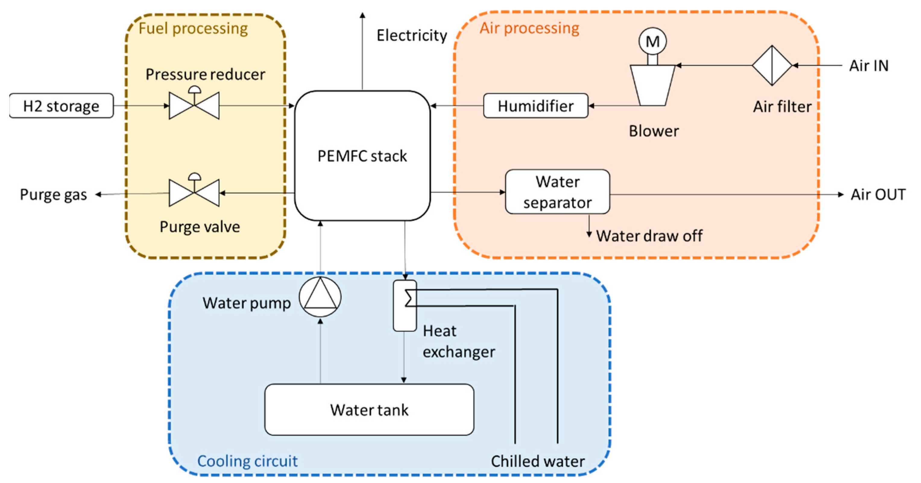
4.2. The Main Power Source: PEMFC
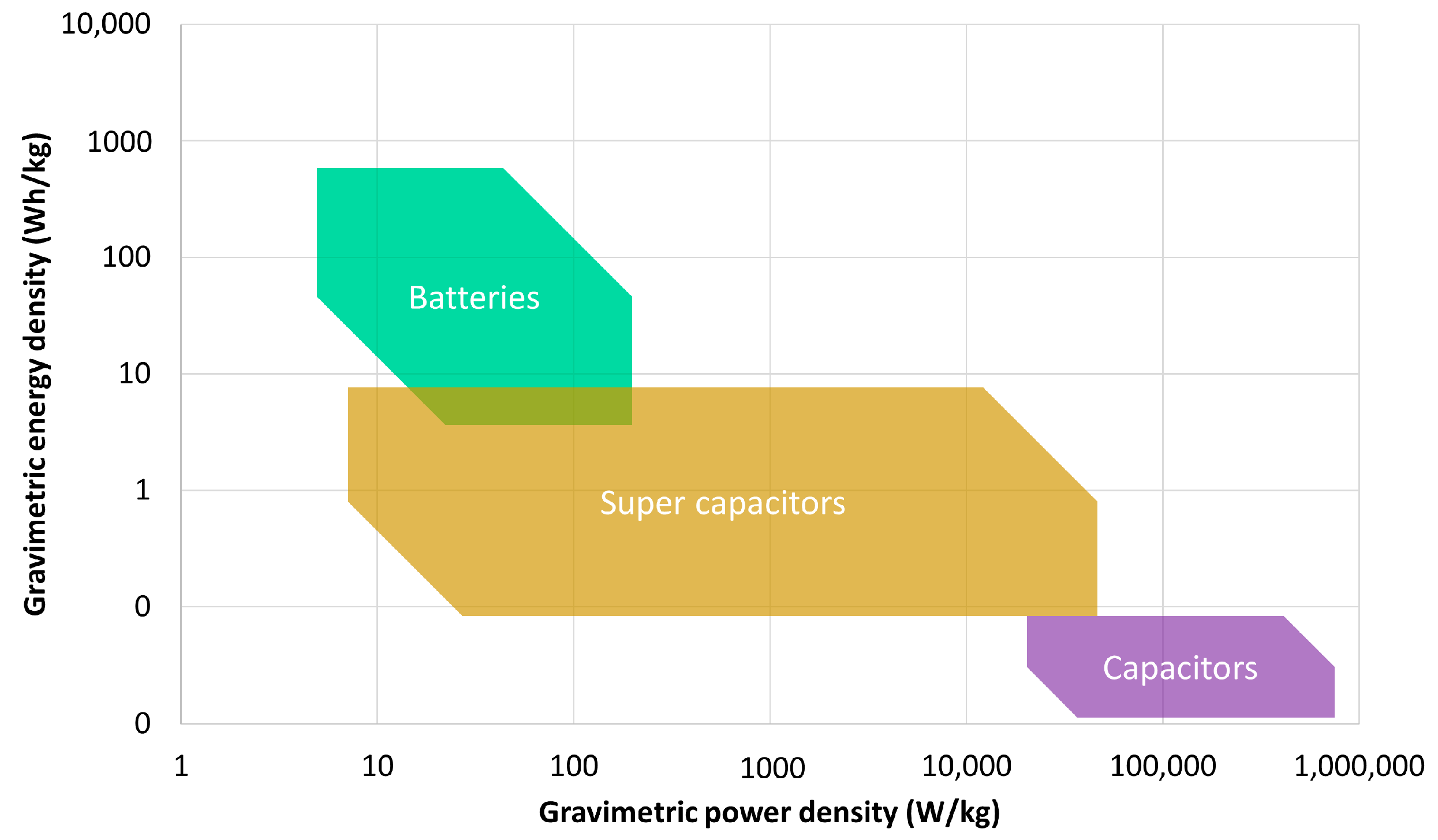
4.3. The Energy Storage System
4.4. Fuel Cells and Battery Degradation
4.5. Energy Management Strategy
5. Regulatory Framework
6. Concluding Remarks and Future Research Trends
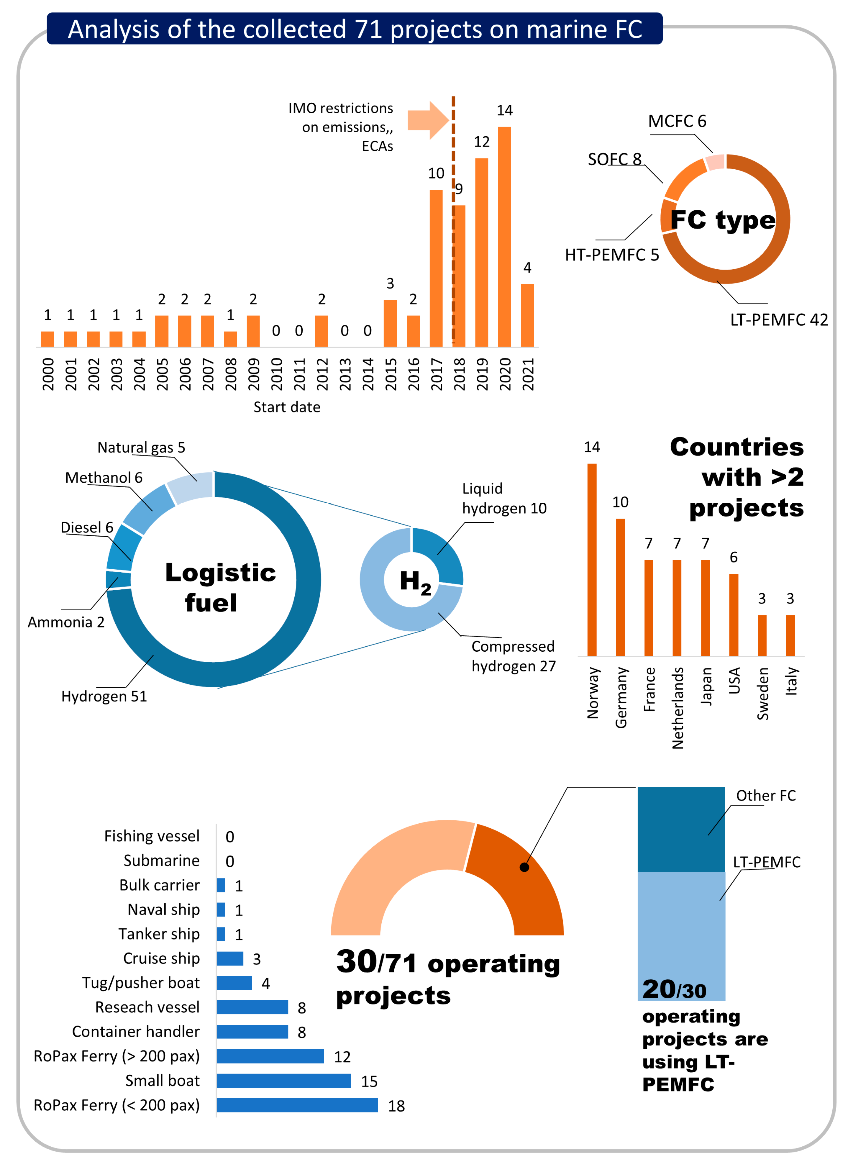
- Projects on fuel cell ships. The current focus of projects in the field of fuel cell ships is primarily on the installation of PEMFCs on small- and medium-sized vessels. The preferred method of hydrogen storage for these projects is compressed hydrogen, although liquid hydrogen storage is gaining traction for larger vessels. It is expected that future projects will involve the installation of fuel cell systems on larger vessels and an increase in the installed power of fuel cell systems.
- Hydrogen storage. One of the main challenges facing the implementation of FC ships is the storage of hydrogen on board. This includes technical, economic, and safety considerations not only for onboard storage but for the entire hydrogen supply chain, from production to bunkering facilities. Currently, hydrogen carriers are not a viable option for PEMFC/energy storage system (ESS) ship propulsion systems, but they may be promising for other types of powertrains such as solid oxide fuel cells (SOFC). Advances in technology for both PEMFC and reforming/cracking units may change this trend.
- Powertrain. Hybrid PEMFC/ESS powertrains are still more expensive than conventional ship propulsion systems. Additionally, the degradation of PEMFCs and ESSs over time can result in shorter lifespans and higher costs. As such, researching ways to optimize the health-conscious management of these systems and using data-driven approaches for real-time optimization are important areas of study. Additionally, future studies should also explore the possibility of recovering heat from PEMFCs to increase the overall plant energy efficiency.
- Onshore infrastructure. Onshore infrastructure for hydrogen and hydrogen carrier supply chains is a crucial area of research not only for academia but also for industry. Future studies should also focus on analysing the onshore power supply infrastructure for vessels at berth, with a specific emphasis on renewable energy systems.
- Regulatory framework. The lack of international rules and standards for PEMFC and hydrogen use in shipping is a significant barrier to the widespread adoption of these technologies. However, guidelines are starting to become available and significant advancements in this area are expected in the coming years.
Supplementary Materials
Author Contributions
Funding
Data Availability Statement
Conflicts of Interest
Nomenclature
| ABS | American Bureau of Shipping |
| AC | Alternating Current |
| ATEX | ATmosphere EXplosive |
| BoP | Balance of Plant |
| BV | Bureau Veritas |
| CcH2 | Cryo-compressed hydrogen |
| CH2 | Compressed hydrogen |
| CO2 | Carbon dioxide |
| DC | Direct Current |
| DMFC | Direct Methanol Fuel Cells |
| DNV-GL | Det Norske Veritas—Germanischer Lloyd |
| DOD | Depth Of Discharge |
| EMS | Energy Management Strategy |
| EMSA | European Maritime Safety Agency |
| ESS | Energy Storage System |
| FC | Fuel Cells |
| FCHEA | Fuel Cell and Hydrogen Energy Association |
| GB | Gearbox |
| GHG | Greenhouse Gas |
| H2 | Hydrogen |
| HFO | Heavy Fuel Oil |
| HT-PEMFC | High-Temperature Polymer Electrolyte Membrane Fuel Cells |
| ICE | Internal Combustion Engine |
| IGF | International Code of Safety for Ships using Gases or other Low-flashpoint Fuels |
| IMO | International Maritime Organization |
| LFP | Lithium iron phosphate |
| LH2 | Liquid hydrogen |
| LIB | Lithium-Ion Batteries |
| LNG | Liquified Natural Gas |
| LOHC | Liquid Organic Hydrogen Carriers |
| LR | Lloyd’s Register |
| LTO | Lithium Titanate Oxide |
| LT-PEMFC | Low-Temperature Polymer Electrolyte Membrane Fuel Cells |
| MCFC | Molten Carbonate Fuel Cells |
| MeOH | Methanol |
| MH | Metal Hydrides |
| NCA | Nickel Cobalt Aluminium |
| NG | Natural Gas |
| NH3 | Ammonia |
| NMC | Nickel Manganese Cobalt |
| NOx | Nitrogen oxides |
| Pax | Passengers |
| PBU | Pressure-Building Unit |
| PEMFC | Proton Exchange Membrane Fuel Cells |
| SC | Supercapacitors |
| SEI | Solid Electrolyte Interface |
| SOC | State Of Charge |
| SOFC | Solid Oxide Fuel Cells |
| SOLAS | International Convention for the Safety of Life at SEA |
References
- European Commission Reducing Emissions from the Shipping Sector. Available online: https://ec.europa.eu/clima/eu-action/transport-emissions/reducing-emissions-shipping-sector_en (accessed on 14 February 2022).
- Fourth Greenhouse Gas Study 2020. Available online: https://www.imo.org/en/OurWork/Environment/Pages/Fourth-IMO-Greenhouse-Gas-Study-2020.aspx (accessed on 23 February 2022).
- International Maritime Organization. Initial IMO Strategy on Reduction of GHG Emissions from Ships; International Maritime Organization: London, UK, 2018. [Google Scholar]
- Lion, S.; Vlaskos, I.; Taccani, R. A review of emissions reduction technologies for low and medium speed marine Diesel engines and their potential for waste heat recovery. Energy Convers. Manag. 2020, 207, 112553. [Google Scholar] [CrossRef]
- Ahmadzadehtalatapeh, M.; Mousavi, M. A Review on the Drag Reduction Methods of the Ship Hulls for Improving the Hydrodynamic Performance. Int. J. Marit. Technol. 2015, 4, 51–64. [Google Scholar]
- Molland, A.F.; Turnock, S.R.; Hudson, D.A.; Utama, I.K.A.P. Reducing ship emissions: A review of potential practical improvements in the propulsive efficiency of future ships. Trans. R. Inst. Nav. Archit. Part A Int. J. Marit. Eng. 2014, 156, 175–188. [Google Scholar] [CrossRef]
- Yu, H.; Fang, Z.; Fu, X.; Liu, J.; Chen, J. Literature review on emission control-based ship voyage optimization. Transp. Res. Part D Transp. Environ. 2021, 93, 102768. [Google Scholar] [CrossRef]
- Ancona, M.A.; Baldi, F.; Bianchi, M.; Branchini, L.; Melino, F.; Peretto, A.; Rosati, J. Efficiency improvement on a cruise ship: Load allocation optimization. Energy Convers. Manag. 2018, 164, 42–58. [Google Scholar] [CrossRef]
- Azzara, A.; Rutherford, D.; Wang, H. Feasibility of IMO Annex VI Tier III implementation using Selective Catalytic Reduction. Int. Counc. Clean Transp. 2014, 4, 1–9. [Google Scholar]
- Burel, F.; Taccani, R.; Zuliani, N. Improving sustainability of maritime transport through utilization of Liquefied Natural Gas (LNG) for propulsion. Energy 2013, 57, 412–420. [Google Scholar] [CrossRef]
- Al-Enazi, A.; Okonkwo, E.C.; Bicer, Y.; Al-Ansari, T. A review of cleaner alternative fuels for maritime transportation. Energy Rep. 2021, 7, 1962–1985. [Google Scholar] [CrossRef]
- Van Hoecke, L.; Laffineur, L.; Campe, R.; Perreault, P.; Verbruggen, S.W.; Lenaerts, S. Challenges in the use of hydrogen for maritime applications. Energy Environ. Sci. 2021, 14, 815–843. [Google Scholar] [CrossRef]
- van Biert, L.; Godjevac, M.; Visser, K.; Aravind, P.V. A review of fuel cell systems for maritime applications. J. Power Sources 2016, 327, 345–364. [Google Scholar] [CrossRef] [Green Version]
- Tronstad, T.; Høgmoen, H.; Gerd, Å.; Haugom, P.; Langfeldt, L. Study on the Use of Fuel Cells in Shipping; EMSA European Maritime Safety Agency: Lisbon, Portugal, 2017.
- Reusser, C.A.; Pérez Osses, J.R. Challenges for Zero-Emissions Ship. J. Mar. Sci. Eng. 2021, 9, 1042. [Google Scholar] [CrossRef]
- Dall’Armi, C.; Micheli, D.; Taccani, R. Comparison of different plant layouts and fuel storage solutions for fuel cells utilization on a small ferry. Int. J. Hydrogen Energy 2021, 46, 13878–13897. [Google Scholar] [CrossRef]
- Balestra, L.; Schjølberg, I. Modelling and simulation of a zero-emission hybrid power plant for a domestic ferry. Int. J. Hydrogen Energy 2021, 46, 10924–10938. [Google Scholar] [CrossRef]
- Wu, P.; Partridge, J.; Bucknall, R. Cost-effective reinforcement learning energy management for plug-in hybrid fuel cell and battery ships. Appl. Energy 2020, 275, 115258. [Google Scholar] [CrossRef]
- Wu, P.; Partridge, J.; Anderlini, E.; Liu, Y.; Bucknall, R. Near-optimal energy management for plug-in hybrid fuel cell and battery propulsion using deep reinforcement learning. Int. J. Hydrogen Energy 2021, 46, 40022–40040. [Google Scholar] [CrossRef]
- Han, J.; Charpentier, J.F.; Tang, T. An Energy Management System of a Fuel Cell/Battery Hybrid Boat. Energies 2014, 7, 2799–2820. [Google Scholar] [CrossRef] [Green Version]
- Balestra, L.; Schjølberg, I. Energy management strategies for a zero-emission hybrid domestic ferry. Int. J. Hydrogen Energy 2021, 46, 38490–38503. [Google Scholar] [CrossRef]
- Pivetta, D.; Dall’Armi, C.; Taccani, R. Multi-objective optimization of hybrid PEMFC/Li-ion battery propulsion systems for small and medium size ferries. Int. J. Hydrogen Energy 2021, 46, 35949–35960. [Google Scholar] [CrossRef]
- Dall’armi, C.; Pivetta, D.; Taccani, R. Health-Conscious Optimization of Long-Term Operation for Hybrid PEMFC Ship Propulsion Systems. Energies 2021, 14, 3813. [Google Scholar] [CrossRef]
- Inal, O.B.; Charpentier, J.F.; Deniz, C. Hybrid power and propulsion systems for ships: Current status and future challenges. Renew. Sustain. Energy Rev. 2022, 156, 111965. [Google Scholar] [CrossRef]
- Sürer, M.G.; Arat, H.T. Advancements and current technologies on hydrogen fuel cell applications for marine vehicles. Int. J. Hydrogen Energy 2022, 47, 19865–19875. [Google Scholar] [CrossRef]
- De-Troya, J.J.; Álvarez, C.; Fernández-Garrido, C.; Carral, L. Analysing the possibilities of using fuel cells in ships. Int. J. Hydrogen Energy 2016, 41, 2853–2866. [Google Scholar] [CrossRef]
- ShipFC Project Website—European Commission. Available online: https://cordis.europa.eu/project/id/875156 (accessed on 23 February 2022).
- Rivard, E.; Trudeau, M.; Zaghib, K. Hydrogen Storage for Mobility: A Review. Materials 2019, 12, 1973. [Google Scholar] [CrossRef] [Green Version]
- Barthélémy, H. Hydrogen storage—Industrial prospectives. Int. J. Hydrogen Energy 2012, 37, 17364–17372. [Google Scholar] [CrossRef]
- Barthelemy, H.; Weber, M.; Barbier, F. Hydrogen storage: Recent improvements and industrial perspectives. Int. J. Hydrogen Energy 2017, 42, 7254–7262. [Google Scholar] [CrossRef]
- Wang, Z.; Wang, Y.; Afshan, S.; Hjalmarsson, J. A review of metallic tanks for H2 storage with a view to application in future green shipping. Int. J. Hydrogen Energy 2021, 46, 6151–6179. [Google Scholar] [CrossRef]
- Stolten, D.; Emonts, B. Hydrogen Science and Engineering, 2 Volume Set: Materials, Processes, Systems, and Technology; John Wiley & Sons: Hoboken, NJ, USA, 2016. [Google Scholar]
- Taccani, R.; Malabotti, S.; Dall’armi, C.; Micheli, D. High energy density storage of gaseous marine fuels: An innovative concept and its application to a hydrogen powered ferry. Int. Shipbuild. Prog. 2020, 67, 33–56. [Google Scholar] [CrossRef]
- NGV Technology-Type 4 Cylinders. Available online: http://ngvtechnology.com/type-4.html (accessed on 10 January 2022).
- Hexagon Purus. Hydrogen High-Pressure Type 4 Cylinders. Available online: https://hexagonpurus.com/our-solutions/hydrogen-systems/hydrogen-type-4-cylinders (accessed on 10 January 2022).
- Cryofab Website. Available online: https://www.cryofab.com/wp-content/uploads/2019/08/Cryofab_CLH_Series_Specs_400.pdf (accessed on 10 January 2022).
- NGV Technology-Type 2 Cylinders. Available online: http://ngvtechnology.com/type-2.html (accessed on 10 January 2022).
- Worthington Industries Website. Available online: https://worthingtonindustries.com/getmedia/26ed37f0-590c-4666-99b7-fce44f40c59c/Hydrogen-Type-3-Spec-sheet_040717_web.pdf?ext=.pdf (accessed on 10 January 2022).
- Pivetta, D.; Dall’armi, C.; Taccani, R. Multi-Objective Optimization of a Hydrogen Hub for the Decarbonization of a Port Industrial Area. J. Mar. Sci. Eng. 2022, 10, 231. [Google Scholar] [CrossRef]
- Hyde, K.; Ellis, A. DUAL Ports De-Carbonising Port Business Today Feasibility of Hydrogen Bunkering; ITM Power: Sheffield, UK, 2019. [Google Scholar]
- Galassi, M.C.; Baraldi, D.; Acosta Iborra, B.; Moretto, P. CFD analysis of fast filling scenarios for 70 MPa hydrogen type IV tanks. Int. J. Hydrogen Energy 2012, 37, 6886–6892. [Google Scholar] [CrossRef]
- Heitsch, M.; Baraldi, D.; Moretto, P. Numerical investigations on the fast filling of hydrogen tanks. Int. J. Hydrogen Energy 2011, 36, 2606–2612. [Google Scholar] [CrossRef]
- Norwegian Centres of Expertise (NCE). Maritime CleanTech Norwegian Future Value Chains for Liquid Hydrogen; Norwegian Centres of Expertise (NCE): Oslo, Norwegian, 2019. [Google Scholar]
- Kawasaki Heavy Industries, Ltd. Available online: https://global.kawasaki.com/en/ (accessed on 14 January 2022).
- Baird Maritime HYDRA—Norled Takes Delivery of Ferry Designed to Run on Liquid Hydrogen. Available online: https://www.bairdmaritime.com/ (accessed on 11 January 2022).
- Norled and Partners in FLAGSHIPS Receives EU-Funding. Available online: https://www.norled.no/en/ (accessed on 2 March 2022).
- Klebanoff, L.E.; Pratt, J.W.; Madsen, R.T.; Caughlan, S.A.M.; Leach, T.S.; Appelgate, T.B.; Kelety, S.Z.; Wintervoll, H.-C.; Haugom, G.P.; Teo, A.T.Y. Feasibility of the Zero-V: A Zero-Emission, Hydrogen Fuel-Cell, Coastal Research Vessel Leonard; Sandia National Lab.: Livermore, CA, USA, 2018. [Google Scholar]
- Klebanoff, L.E.; Pratt, J.W.; LaFleur, C.B. Comparison of the safety-related physical and combustion properties of liquid hydrogen and liquid natural gas in the context of the SF-BREEZE high-speed fuel-cell ferry. Int. J. Hydrogen Energy 2017, 42, 757–774. [Google Scholar] [CrossRef] [Green Version]
- Pratt, J.W.; Klebanoff, L.E. Feasibility of the SF-BREEZE: A Zero-Emission, Hydrogen Fuel Cell, High-Speed Passenger Ferry. 2017. Available online: https://rosap.ntl.bts.gov/view/dot/51783 (accessed on 12 February 2023).
- Rødne E-Maran: Report Fase 2—Konsortiet Rødne Trafikk AS (in Norwegian). 2019. Available online: https://www.skyss.no/globalassets/om-skyss/strategiar-og-fagstoff/fagrapportar-og-utgreiingar/2021/utgreiing-av-kollektivtransport-til-sjos_asplan-viak_030321-4.pdf (accessed on 12 February 2023).
- DNV-GL. Assessment of Selected Alternative Fuels and Technologies in Shipping; DNV-GL: Bayrum, Norway, 2019. [Google Scholar]
- Barron, R.F.; Nellis, G.F. Cryogenic Heat Transfer; CRC Press: Boca Raton, FL, USA, 2016. [Google Scholar]
- Aceves, S.M.; Berry, G.D.; Martinez-Frias, J.; Espinosa-Loza, F. Vehicular storage of hydrogen in insulated pressure vessels. Int. J. Hydrogen Energy 2006, 31, 2274–2283. [Google Scholar] [CrossRef] [Green Version]
- FuelCellsWorks Website—Norse Group Announces Launch of MF Hydra, World’s First LH2 Driven Ferry Boat. Available online: https://fuelcellsworks.com/news/norse-group-announces-launch-of-mf-hydra-worlds-first-lh2-driven-ferry-boat/ (accessed on 25 February 2022).
- World’s First Liquid Hydrogen Bunkering Facility for Fuelling Zero-Emission Ships Revealed—Offshore Energy. Available online: https://www.offshore-energy.biz/worlds-first-liquid-hydrogen-bunkering-facility-for-fuelling-zero-emission-ships-revealed/ (accessed on 23 February 2022).
- HESC Project Website—Hydrogen Energy Supply Chain. Available online: https://www.hydrogenenergysupplychain.com/ (accessed on 24 January 2023).
- Cryostar Website. Available online: https://cryostar.com/hydrogen/ (accessed on 17 January 2022).
- Linde Engineering. Available online: https://www.linde-engineering.com/en/ (accessed on 17 January 2022).
- HySTRA—CO2-Free Hydrogen Energy Supply-Chain Technology Research Association. Available online: http://www.hystra.or.jp/en/ (accessed on 14 January 2022).
- REShiP: Renewable Energy Ship Propulsion. Available online: https://www.lr.org/en/latest-news/reship-renewable-energy-ship-propulsion/ (accessed on 9 February 2023).
- HyShip—Web Page. Available online: https://hyship.eu/ (accessed on 9 February 2023).
- Klier, J.; Rattey, M.; Kaiser, G.; Klupsch, M.; Kade, A.; Schneider, M.; Herzog, R. A new cryogenic high-pressure H2 test area: First results. In Proceedings of the 12th Cryogenics 2012 IIR International Conference, Dresden, Germany, 11–14 September 2012. [Google Scholar]
- Ahluwalia, R.K.; Peng, J.-K.; Hua, T.Q. Cryo-compressed hydrogen storage. Compend. Hydrog. Energy 2016, 2, 119–145. [Google Scholar] [CrossRef]
- Meneghelli, B.; Tamburello, D.; Fesmire, J.; Swanger, A.; Manager, D.; Adams, J. Integrated Insulation System for Automotive Cryogenic Storage Tanks. In DOE Hydrogen and Fuel Cells Program FY 2017 Annual Progress Report; United States Department of Energy: Washington, DC, USA, 2017. [Google Scholar]
- Ahluwalia, R.K.; Peng, J.K.; Roh, H.S.; Hua, T.Q.; Houchins, C.; James, B.D. Supercritical cryo-compressed hydrogen storage for fuel cell electric buses. Int. J. Hydrogen Energy 2018, 43, 10215–10231. [Google Scholar] [CrossRef]
- Ahluwalia, R.K.; Hua, T.Q.; Peng, J.K.; Lasher, S.; McKenney, K.; Sinha, J.; Gardiner, M. Technical assessment of cryo-compressed hydrogen storage tank systems for automotive applications. Int. J. Hydrogen Energy 2010, 35, 4171–4184. [Google Scholar] [CrossRef]
- Aceves, S.M.; Petitpas, G.; Espinosa-Loza, F.; Matthews, M.J.; Ledesma-Orozco, E. Safe, long range, inexpensive and rapidly refuelable hydrogen vehicles with cryogenic pressure vessels. Int. J. Hydrogen Energy 2013, 38, 2480–2489. [Google Scholar] [CrossRef]
- Kunze, K.; Kircher, O. Cryo-Compressed Hydrogen Storage. Available online: https://stfc.ukri.org/stfc/cache/file/F45B669C-73BF-495B-B843DCDF50E8B5A5.pdf (accessed on 28 February 2022).
- Reed, R.P.; Golda, M. Cryogenic properties of unidirectional composites. Cryogenics 1994, 34, 909–928. [Google Scholar] [CrossRef]
- Cavo, M.; Gadducci, E.; Rivarolo, M.; Magistri, L.; Dellacasa, A.; Romanello, M.; Borgogna, G.; Davico, C. Thermal integration of PEM Fuel Cells and metal hydrides storage system for Zero Emission Ultimate Ship (ZEUS). E3S Web Conf. 2022, 334, 04004. [Google Scholar] [CrossRef]
- Lototskyy, M.V.; Tolj, I.; Pickering, L.; Sita, C.; Barbir, F.; Yartys, V. The use of metal hydrides in fuel cell applications. Prog. Nat. Sci. Mater. Int. 2017, 27, 3–20. [Google Scholar] [CrossRef] [Green Version]
- Rusman, N.A.A.; Dahari, M. A review on the current progress of metal hydrides material for solid-state hydrogen storage applications. Int. J. Hydrogen Energy 2016, 41, 12108–12126. [Google Scholar] [CrossRef]
- Bellosta von Colbe, J.; Ares, J.R.; Barale, J.; Baricco, M.; Buckley, C.; Capurso, G.; Gallandat, N.; Grant, D.M.; Guzik, M.N.; Jacob, I.; et al. Application of hydrides in hydrogen storage and compression: Achievements, outlook and perspectives. Int. J. Hydrogen Energy 2019, 44, 7780–7808. [Google Scholar] [CrossRef]
- Netskina, O.V.; Tayban, E.S.; Prosvirin, I.P.; Komova, O.V.; Simagina, V.I. Hydrogen storage systems based on solid-state NaBH4/Co composite: Effect of catalyst precursor on hydrogen generation rate. Renew. Energy 2020, 151, 278–285. [Google Scholar] [CrossRef]
- Kumar, R.; Karkamkar, A.; Bowden, M.; Autrey, T. Solid-state hydrogen rich boron–nitrogen compounds for energy storage. Chem. Soc. Rev. 2019, 48, 5350–5380. [Google Scholar] [CrossRef]
- Zhang, J.; Li, Z.; Wu, Y.; Guo, X.; Ye, J.; Yuan, B.; Wang, S.; Jiang, L. Recent advances on the thermal destabilization of Mg-based hydrogen storage materials. RSC Adv. 2018, 9, 408–428. [Google Scholar] [CrossRef] [PubMed] [Green Version]
- Zacharia, R.; Rather, S.U. Review of solid state hydrogen storage methods adopting different kinds of novel materials. J. Nanomater. 2015, 2015, 1–18. [Google Scholar] [CrossRef] [Green Version]
- Zhang, J.; Zhu, Y.; Yao, L.; Xu, C.; Liu, Y.; Li, L. State of the art multi-strategy improvement of Mg-based hydrides for hydrogen storage. J. Alloy. Compd. 2019, 782, 796–823. [Google Scholar] [CrossRef]
- Shang, Y.; Pistidda, C.; Gizer, G.; Klassen, T.; Dornheim, M. Mg-based materials for hydrogen storage. J. Magnes. Alloy. 2021, 9, 1837–1860. [Google Scholar] [CrossRef]
- Zhang, X.; Zhang, Q.; Xu, B.; Liu, X.; Zhang, K.; Fan, G.; Jiang, W. Efficient Hydrogen Generation from the NaBH4 Hydrolysis by Cobalt-Based Catalysts: Positive Roles of Sulfur-Containing Salts. ACS Appl. Mater. Interfaces 2020, 12, 9376–9386. [Google Scholar] [CrossRef]
- Fiori, C.; Dell’Era, A.; Zuccari, F.; Santiangeli, A.; D’Orazio, A.; Orecchini, F. Hydrides for submarine applications: Overview and identification of optimal alloys for air independent propulsion maximization. Int. J. Hydrogen Energy 2015, 40, 11879–11889. [Google Scholar] [CrossRef]
- Chabane, D.; Ibrahim, M.; Harel, F.; Djerdir, A.; Candusso, D.; Elkedim, O. Energy management of a thermally coupled fuel cell system and metal hydride tank. Int. J. Hydrogen Energy 2019, 44, 27553–27563. [Google Scholar] [CrossRef]
- Wang, Y.; Wright, L.A.; Bergman, M. A Comparative Review of Alternative Fuels for the Maritime Sector: Economic, Technology, and Policy Challenges for Clean Energy Implementation. World 2021, 2, 456–481. [Google Scholar] [CrossRef]
- Hansson, J.; Fridell, E.; Brynolf, S. On the Potential of Ammonia as Fuel for Shipping: A Synthesis of Knowledge. 2020. Available online: https://trid.trb.org/view/1706562 (accessed on 12 February 2023).
- Zhang, H.; Wang, L.; Van Herle, J.; Maréchal, F.; Desideri, U. Techno-economic comparison of green ammonia production processes. Appl. Energy 2020, 259, 114135. [Google Scholar] [CrossRef]
- Kim, K.; Roh, G.; Kim, W.; Chun, K. A Preliminary Study on an Alternative Ship Propulsion System Fueled by Ammonia: Environmental and Economic Assessments. J. Mar. Sci. Eng. 2020, 8, 183. [Google Scholar] [CrossRef] [Green Version]
- McKinlay, C.J.; Turnock, S.R.; Hudson, D.A. Route to zero emission shipping: Hydrogen, ammonia or methanol? Int. J. Hydrogen Energy 2021, 46, 28282–28297. [Google Scholar] [CrossRef]
- Soto, H.J.; Lee, W.K.; Van Zee, J.W.; Murthy, M. Effect of transient ammonia concentrations on PEMFC performance. Electrochem. Solid-State Lett. 2003, 6, A133. [Google Scholar] [CrossRef]
- Trivyza, N.L.; Cheliotis, M.; Boulougouris, E.; Theotokatos, G. Safety and Reliability Analysis of an Ammonia-Powered Fuel-Cell System. Safety 2021, 7, 80. [Google Scholar] [CrossRef]
- Sheldon, D. Methanol production-a technical history. Johns. Matthey Technol. Rev. 2017, 61, 172–182. [Google Scholar] [CrossRef]
- Alvarado, M. The changing face of the global methanol industry. IHS Chem. Bull. 2016, 3, 10–11. [Google Scholar]
- Svanberg, M.; Ellis, J.; Lundgren, J.; Landälv, I. Renewable methanol as a fuel for the shipping industry. Renew. Sustain. Energy Rev. 2018, 94, 1217–1228. [Google Scholar] [CrossRef]
- International Maritime Organization. Methanol as Marine Fuel: Environmental Benefits, Technology Readiness, and Economic Feasibility; International Maritime Organization: London, UK, 2016. [Google Scholar]
- Aakko-Saksa, P.T.; Cook, C.; Kiviaho, J.; Repo, T. Liquid organic hydrogen carriers for transportation and storing of renewable energy—Review and discussion. J. Power Sources 2018, 396, 803–823. [Google Scholar] [CrossRef]
- Teichmann, D.; Arlt, W.; Wasserscheid, P. Liquid Organic Hydrogen Carriers as an efficient vector for the transport and storage of renewable energy. Int. J. Hydrogen Energy 2012, 37, 18118–18132. [Google Scholar] [CrossRef]
- Preuster, P.; Alekseev, A.; Wasserscheid, P. Hydrogen Storage Technologies for Future Energy Systems. Annu. Rev. Chem. Biomol. Eng. 2017, 8, 445–471. [Google Scholar] [CrossRef] [PubMed]
- Preuster, P.; Fang, Q.; Peters, R.; Deja, R.; Nguyen, V.N.; Blum, L.; Stolten, D.; Wasserscheid, P. Solid oxide fuel cell operating on liquid organic hydrogen carrier-based hydrogen—Making full use of heat integration potentials. Int. J. Hydrogen Energy 2018, 43, 1758–1768. [Google Scholar] [CrossRef]
- Luschtinetz, T.; Sklarow, A.; Gulden, J. Degradation effects on PEM fuel cells supplied with hydrogen from a LOHC system. Appl. Mech. Mater. 2016, 839, 165–169. [Google Scholar] [CrossRef]
- Hydrogenious LOHC Maritime. Available online: https://www.hydrogenious-maritime.net/ (accessed on 9 February 2023).
- Shi, W.; Yi, B.; Hou, M.; Shao, Z. The effect of H2S and CO mixtures on PEMFC performance. Int. J. Hydrogen Energy 2007, 32, 4412–4417. [Google Scholar] [CrossRef]
- Micoli, L.; Coppola, T.; Turco, M. A Case Study of a Solid Oxide Fuel Cell Plant on Board a Cruise Ship. J. Mar. Sci. Appl. 2021, 20, 524–533. [Google Scholar] [CrossRef]
- Bloom SOFC to power Korean LNG ship. Fuel Cells Bull. 2021, 2021, 8. [CrossRef]
- International Energy Agency Global Hydrogen Review 2021; OECD Publishing: Paris, France, 2021.
- Dias, V.; Pochet, M.; Contino, F.; Jeanmart, H. Energy and Economic Costs of Chemical Storage. Front. Mech. Eng. 2020, 6, 21. [Google Scholar] [CrossRef]
- Thounthong, P.; Chunkag, V.; Sethakul, P.; Davat, B.; Hinaje, M. Comparative study of fuel-cell vehicle hybridization with battery or supercapacitor storage device. IEEE Trans. Veh. Technol. 2009, 58, 3892–3904. [Google Scholar] [CrossRef]
- Geertsma, R.D.; Negenborn, R.R.; Visser, K.; Hopman, J.J. Design and control of hybrid power and propulsion systems for smart ships: A review of developments. Appl. Energy 2017, 194, 30–54. [Google Scholar] [CrossRef]
- Manoharan, Y.; Hosseini, S.E.; Butler, B.; Alzhahrani, H.; Senior, B.T.F.; Ashuri, T.; Krohn, J. Hydrogen Fuel Cell Vehicles; Current Status and Future Prospect. Appl. Sci. 2019, 9, 2296. [Google Scholar] [CrossRef] [Green Version]
- Bosich, D.; Giadrossi, G.; Pastore, S.; Sulligoi, G. Weighted Bandwidth Method for Stability Assessment of Complex DC Power Systems on Ships. Energies 2021, 15, 258. [Google Scholar] [CrossRef]
- Prenc, R.; Cuculić, A.; Baumgartner, I. Advantages of using a DC power system on board ship. Pomor. Zb. 2016, 52, 83–97. [Google Scholar] [CrossRef] [Green Version]
- Wu, P.; Bucknall, R. Hybrid fuel cell and battery propulsion system modelling and multi-objective optimisation for a coastal ferry. Int. J. Hydrogen Energy 2020, 45, 3193–3208. [Google Scholar] [CrossRef]
- Innes, A.; Monios, J. Identifying the unique challenges of installing cold ironing at small and medium ports—The case of aberdeen. Transp. Res. Part D Transp. Environ. 2018, 62, 298–313. [Google Scholar] [CrossRef]
- Gutierrez-Romero, J.E.; Esteve-Pérez, J.; Zamora, B. Implementing Onshore Power Supply from renewable energy sources for requirements of ships at berth. Appl. Energy 2019, 255, 113883. [Google Scholar] [CrossRef]
- Ulstein Website—SX190 Zero Emission DP2. Available online: https://ulstein.com/vessel-design/sx190 (accessed on 24 February 2022).
- NCE Maritime CleanTech Website -ZeFF: Towards Zero Emission Fast Ferries. Available online: https://maritimecleantech.no/2019/01/15/zeff-towards-zero-emission-fast-ferries/ (accessed on 24 February 2022).
- Ahmadi, N.; Dadvand, A.; Rezazadeh, S.; Mirzaee, I. Analysis of the operating pressure and GDL geometrical configuration effect on PEM fuel cell performance. J. Braz. Soc. Mech. Sci. Eng. 2016, 38, 2311–2325. [Google Scholar] [CrossRef]
- Xing, H.; Stuart, C.; Spence, S.; Chen, H. Fuel Cell Power Systems for Maritime Applications: Progress and Perspectives. Sustainability 2021, 13, 1213. [Google Scholar] [CrossRef]
- Sasank, B.V.; Rajalakshmi, N.; Dhathathreyan, K.S. Performance analysis of polymer electrolyte membrane (PEM) fuel cell stack operated under marine environmental conditions. J. Mar. Sci. Technol. 2016, 21, 471–478. [Google Scholar] [CrossRef]
- Yan, W.M.; Wang, X.D.; Mei, S.S.; Peng, X.F.; Guo, Y.F.; Su, A. Effects of operating temperatures on performance and pressure drops for a 256 cm2 proton exchange membrane fuel cell: An experimental study. J. Power Sources 2008, 185, 1040–1048. [Google Scholar] [CrossRef]
- Nguyen, H.Q.; Shabani, B. Proton exchange membrane fuel cells heat recovery opportunities for combined heating/cooling and power applications. Energy Convers. Manag. 2020, 204, 112328. [Google Scholar] [CrossRef]
- Pietra, A.; Gianni, M.; Zuliani, N.; Malabotti, S.; Taccani, R. Experimental characterization of a PEM fuel cell for marine power generation. E3S Web Conf. 2022, 334, 05002. [Google Scholar] [CrossRef]
- The Future of Hydrogen-Analysis-IEA. Available online: https://www.iea.org/reports/the-future-of-hydrogen (accessed on 23 February 2022).
- Zhao, J.; Tu, Z.; Chan, S.H. Carbon corrosion mechanism and mitigation strategies in a proton exchange membrane fuel cell (PEMFC): A review. J. Power Sources 2021, 488, 229434. [Google Scholar] [CrossRef]
- EMSA European Maritime Safety Agency. Study on Electrical Energy Storage for Ships; European Maritime Safety Agency: Lisbon, Portugal, 2020.
- Vogler, F.; Würsig, G. Fuel cells in maritime applications. Challenges, chances and experiences. In Proceedings of the International Conference on Hydrogen Safety, San Francisco, CA, USA, 12–14 September 2011. [Google Scholar]
- NemoH2—Web Page. Available online: http://www.opr-advies.nl/fuelcellboat/efcbabout.html (accessed on 9 February 2023).
- González, A.; Goikolea, E.; Barrena, J.A.; Mysyk, R. Review on supercapacitors: Technologies and materials. Renew. Sustain. Energy Rev. 2016, 58, 1189–1206. [Google Scholar] [CrossRef]
- Ongaro, F.; Saggini, S.; Mattavelli, P. Li-Ion battery-supercapacitor hybrid storage system for a long lifetime, photovoltaic-based wireless sensor network. IEEE Trans. Power Electron. 2012, 27, 3944–3952. [Google Scholar] [CrossRef]
- Williams, N.G.; Lu, D.; McVey, J.R.; Cavagnaro, R.J. A Comparative Analysis of Lithium-Ion Battery Chemistries for Cold-Climate Maritime Applications; Pacific Northwest National Lab. (PNNL): Richland, WA, USA, 2021. [Google Scholar] [CrossRef]
- Manthiram, A. An Outlook on Lithium Ion Battery Technology. ACS Cent. Sci. 2017, 3, 1063–1069. [Google Scholar] [CrossRef] [Green Version]
- Leclanché Website—E-Marine. Available online: https://www.leclanche.com/solutions/e-transport-solutions/e-marine/ (accessed on 23 February 2022).
- Reddy, N.P.; Zadeh, M.K.; Thieme, C.A.; Skjetne, R.; Sorensen, A.J.; Aanondsen, S.A.; Breivik, M.; Eide, E. Zero-emission autonomous ferries for urban water transport: Cheaper, cleaner alternative to bridges and manned vessels. IEEE Electrif. Mag. 2019, 7, 32–45. [Google Scholar] [CrossRef]
- XALT Energy Website—Marine. Available online: https://www.xaltenergy.com/marine/ (accessed on 23 February 2022).
- Kim, K.; An, J.; Park, K.; Roh, G.; Chun, K. Analysis of a Supercapacitor/Battery Hybrid Power System for a Bulk Carrier. Appl. Sci. 2019, 9, 1547. [Google Scholar] [CrossRef] [Green Version]
- Wu, P.; Bucknall, R. Marine propulsion using battery power. In Proceedings of the Shipping in Changing Climates Conference, Newcastle, UK, 10–11 November 2016. [Google Scholar]
- Wu, J.; Yuan, X.Z.; Martin, J.J.; Wang, H.; Zhang, J.; Shen, J.; Wu, S.; Merida, W. A review of PEM fuel cell durability: Degradation mechanisms and mitigation strategies. J. Power Sources 2008, 184, 104–119. [Google Scholar] [CrossRef]
- Mayur, M.; Gerard, M.; Schott, P.; Bessler, W.G. Lifetime Prediction of a Polymer Electrolyte Membrane Fuel Cell under Automotive Load Cycling Using a Physically-Based Catalyst Degradation Model. Energies 2018, 11, 2054. [Google Scholar] [CrossRef] [Green Version]
- Lorenzo, C.; Bouquain, D.; Hibon, S.; Hissel, D. Synthesis of degradation mechanisms and of their impacts on degradation rates on proton-exchange membrane fuel cells and lithium-ion nickel–manganese–cobalt batteries in hybrid transport applications. Reliab. Eng. Syst. Saf. 2021, 212, 107369. [Google Scholar] [CrossRef]
- Oyarce, A.; Zakrisson, E.; Ivity, M.; Lagergren, C.; Ofstad, A.B.; Bodén, A.; Lindbergh, G. Comparing shut-down strategies for proton exchange membrane fuel cells. J. Power Sources 2014, 254, 232–240. [Google Scholar] [CrossRef]
- Brightman, E.; Hinds, G. In situ mapping of potential transients during start-up and shut-down of a polymer electrolyte membrane fuel cell. J. Power Sources 2014, 267, 160–170. [Google Scholar] [CrossRef]
- Péron, J.; Nedellec, Y.; Jones, D.J.; Rozière, J. The effect of dissolution, migration and precipitation of platinum in Nafion®-based membrane electrode assemblies during fuel cell operation at high potential. J. Power Sources 2008, 185, 1209–1217. [Google Scholar] [CrossRef]
- Franck-Lacaze, L.; Bonnet, C.; Choi, E.; Moss, J.; Pontvianne, S.; Poirot, H.; Datta, R.; Lapicque, F. Ageing of PEMFC’s due to operation at low current density: Investigation of oxidative degradation. Int. J. Hydrogen Energy 2010, 35, 10472–10481. [Google Scholar] [CrossRef]
- Fletcher, T.; Thring, R.; Watkinson, M. An Energy Management Strategy to concurrently optimise fuel consumption & PEM fuel cell lifetime in a hybrid vehicle. Int. J. Hydrogen Energy 2016, 41, 21503–21515. [Google Scholar] [CrossRef] [Green Version]
- Wang, G.; Huang, F.; Yu, Y.; Wen, S.; Tu, Z. Degradation behavior of a proton exchange membrane fuel cell stack under dynamic cycles between idling and rated condition. Int. J. Hydrogen Energy 2018, 43, 4471–4481. [Google Scholar] [CrossRef]
- Zhang, X.; Yang, D.; Luo, M.; Dong, Z. Load profile based empirical model for the lifetime prediction of an automotive PEM fuel cell. Int. J. Hydrogen Energy 2017, 42, 11868–11878. [Google Scholar] [CrossRef]
- Cleghorn, S.J.C.; Mayfield, D.K.; Moore, D.A.; Moore, J.C.; Rusch, G.; Sherman, T.W.; Sisofo, N.T.; Beuscher, U. A polymer electrolyte fuel cell life test: 3 years of continuous operation. J. Power Sources 2006, 158, 446–454. [Google Scholar] [CrossRef]
- Fowler, M.W.; Mann, R.F.; Amphlett, J.C.; Peppley, B.A.; Roberge, P.R. Incorporation of voltage degradation into a generalised steady state electrochemical model for a PEM fuel cell. J. Power Sources 2002, 106, 274–283. [Google Scholar] [CrossRef]
- Yue, M.; Jemei, S.; Gouriveau, R.; Zerhouni, N. Review on health-conscious energy management strategies for fuel cell hybrid electric vehicles: Degradation models and strategies. Int. J. Hydrogen Energy 2019, 44, 6844–6861. [Google Scholar] [CrossRef]
- Redondo-Iglesias, E.; Venet, P.; Pelissier, S. Calendar and cycling ageing combination of batteries in electric vehicles. Microelectron. Reliab. 2018, 88–90, 1212–1215. [Google Scholar] [CrossRef] [Green Version]
- Wang, J.; Liu, P.; Hicks-Garner, J.; Sherman, E.; Soukiazian, S.; Verbrugge, M.; Tataria, H.; Musser, J.; Finamore, P. Cycle-life model for graphite-LiFePO4 cells. J. Power Sources 2011, 196, 3942–3948. [Google Scholar] [CrossRef]
- Han, X.; Lu, L.; Zheng, Y.; Feng, X.; Li, Z.; Li, J.; Ouyang, M. A review on the key issues of the lithium ion battery degradation among the whole life cycle. eTransportation 2019, 1, 100005. [Google Scholar] [CrossRef]
- Shahjalal, M.; Roy, P.K.; Shams, T.; Fly, A.; Chowdhury, J.I.; Ahmed, M.R.; Liu, K. A review on second-life of Li-ion batteries: Prospects, challenges, and issues. Energy 2022, 241, 122881. [Google Scholar] [CrossRef]
- Zhang, Y.C.; Briat, O.; Delétage, J.Y.; Martin, C.; Chadourne, N.; Vinassa, J.M. Efficient state of health estimation of Li-ion battery under several ageing types for aeronautic applications. Microelectron. Reliab. 2018, 88–90, 1231–1235. [Google Scholar] [CrossRef]
- Pelletier, S.; Jabali, O.; Laporte, G.; Veneroni, M. Battery degradation and behaviour for electric vehicles: Review and numerical analyses of several models. Transp. Res. Part B Methodol. 2017, 103, 158–187. [Google Scholar] [CrossRef]
- Oz, A.; Gelman, D.; Goren, E.; Shomrat, N.; Baltianski, S.; Tsur, Y. A novel approach for supercapacitors degradation characterization. J. Power Sources 2017, 355, 74–82. [Google Scholar] [CrossRef]
- Oukaour, A.; Tala-Ighil, B.; Alsakka, M.; Gualous, H.; Gallay, R.; Boudart, B. Calendar ageing and health diagnosis of supercapacitor. Electr. Power Syst. Res. 2013, 95, 330–338. [Google Scholar] [CrossRef]
- Kreczanik, P.; Venet, P.; Hijazi, A.; Clerc, G. Study of supercapacitor aging and lifetime estimation according to voltage, temperature, and RMS current. IEEE Trans. Ind. Electron. 2014, 61, 4895–4902. [Google Scholar] [CrossRef]
- Azaïs, P.; Duclaux, L.; Florian, P.; Massiot, D.; Lillo-Rodenas, M.A.; Linares-Solano, A.; Peres, J.P.; Jehoulet, C.; Béguin, F. Causes of supercapacitors ageing in organic electrolyte. J. Power Sources 2007, 171, 1046–1053. [Google Scholar] [CrossRef]
- Zhu, M.; Weber, C.J.; Yang, Y.; Konuma, M.; Starke, U.; Kern, K.; Bittner, A.M. Chemical and electrochemical ageing of carbon materials used in supercapacitor electrodes. Carbon 2008, 46, 1829–1840. [Google Scholar] [CrossRef]
- El Mejdoubi, A.; Oukaour, A.; Chaoui, H.; Gualous, H.; Sabor, J.; Slamani, Y. Prediction Aging Model for Supercapacitor’s Calendar Life in Vehicular Applications. IEEE Trans. Veh. Technol. 2016, 65, 4253–4263. [Google Scholar] [CrossRef]
- Naseri, F.; Karimi, S.; Farjah, E.; Schaltz, E. Supercapacitor management system: A comprehensive review of modeling, estimation, balancing, and protection techniques. Renew. Sustain. Energy Rev. 2022, 155, 111913. [Google Scholar] [CrossRef]
- Liu, C.; Li, Q.; Wang, K. State-of-charge estimation and remaining useful life prediction of supercapacitors. Renew. Sustain. Energy Rev. 2021, 150, 111408. [Google Scholar] [CrossRef]
- Sulaiman, N.; Hannan, M.A.; Mohamed, A.; Majlan, E.H.; Wan Daud, W.R. A review on energy management system for fuel cell hybrid electric vehicle: Issues and challenges. Renew. Sustain. Energy Rev. 2015, 52, 802–814. [Google Scholar] [CrossRef]
- Bassam, A.M.; Phillips, A.B.; Turnock, S.R.; Wilson, P.A. An improved energy management strategy for a hybrid fuel cell/battery passenger vessel. Int. J. Hydrogen Energy 2016, 41, 22453–22464. [Google Scholar] [CrossRef] [Green Version]
- Zhu, L.; Han, J.; Peng, D.; Wang, T.; Tang, T.; Charpentier, J.F. Fuzzy logic based energy management strategy for a fuel cell/battery/ultra-capacitor hybrid ship. In Proceedings of the 2014 First International Conference on Green Energy ICGE 2014, Sfax, Tunisia, 25–27 March 2014; pp. 107–112. [Google Scholar] [CrossRef] [Green Version]
- Tang, D.; Zio, E.; Yuan, Y.; Zhao, J.; Yan, X. The energy management and optimization strategy for fuel cell hybrid ships. In Proceedings of the 2017 2nd International Conference on System Reliability and Safety (ICSRS), Milan, Italy, 20–22 December 2017; pp. 277–281. [Google Scholar] [CrossRef] [Green Version]
- Rivarolo, M.; Rattazzi, D.; Magistri, L. Best operative strategy for energy management of a cruise ship employing different distributed generation technologies. Int. J. Hydrogen Energy 2018, 43, 23500–23510. [Google Scholar] [CrossRef]
- Chen, H.; Zhang, Z.; Guan, C.; Gao, H. Optimization of sizing and frequency control in battery/supercapacitor hybrid energy storage system for fuel cell ship. Energy 2020, 197, 117285. [Google Scholar] [CrossRef]
- Letafat, A.; Rafiei, M.; Sheikh, M.; Afshari-Igder, M.; Banaei, M.; Boudjadar, J.; Khooban, M.H. Simultaneous energy management and optimal components sizing of a zero-emission ferry boat. J. Energy Storage 2020, 28, 101215. [Google Scholar] [CrossRef]
- Rivarolo, M.; Rattazzi, D.; Lamberti, T.; Magistri, L. Clean energy production by PEM fuel cells on tourist ships: A time-dependent analysis. Int. J. Hydrogen Energy 2020, 45, 25747–25757. [Google Scholar] [CrossRef]
- Banaei, M.; Ghanami, F.; Khooban, M.H.; Boudjadar, J. Cost-effective control of Roll-on/Roll-off Emission-Free Ships. In Proceedings of the 2021 25th International Conference on Methods and Models in Automation and Robotics (MMAR) 2021, Międzyzdroje, Poland, 23–26 August 2021; Volume 2021, pp. 315–320. [Google Scholar] [CrossRef]
- Dall’Armi, C.; Pivetta, D.; Taccani, R. Uncertainty analysis of the optimal health-conscious operation of a hybrid PEMFC coastal ferry. Int. J. Hydrogen Energy 2021, 47, 11428–11440. [Google Scholar] [CrossRef]
- Hasanvand, S.; Rafiei, M.; Gheisarnejad, M.; Khooban, M.H. Reliable Power Scheduling of an Emission-Free Ship: Multiobjective Deep Reinforcement Learning. IEEE Trans. Transp. Electrif. 2020, 6, 832–843. [Google Scholar] [CrossRef]
- Vafamand, N.; Boudjadar, J.; Khooban, M.H. Model predictive energy management in hybrid ferry grids. Energy Rep. 2020, 6, 550–557. [Google Scholar] [CrossRef]
- Zhang, Z.; Guan, C.; Liu, Z. Real-Time Optimization Energy Management Strategy for Fuel Cell Hybrid Ships Considering Power Sources Degradation. IEEE Access 2020, 8, 87046–87059. [Google Scholar] [CrossRef]
- Rezk, H.; Nassef, A.M.; Abdelkareem, M.A.; Alami, A.H.; Fathy, A. Comparison among various energy management strategies for reducing hydrogen consumption in a hybrid fuel cell/supercapacitor/battery system. Int. J. Hydrogen Energy 2021, 46, 6110–6126. [Google Scholar] [CrossRef]
- Bassam, A.M.; Phillips, A.B.; Turnock, S.R.; Wilson, P.A. Development of a multi-scheme energy management strategy for a hybrid fuel cell driven passenger ship. Int. J. Hydrogen Energy 2017, 42, 623–635. [Google Scholar] [CrossRef] [Green Version]
- DNV-GL. Handbook for Hydrogen-Fuelled Vessels; DNV-GL: Bayrum, Norway, 2021. [Google Scholar]
- Bourne, C.; Nietsch, T.; Griffiths, D.; Morley, J. Application of Fuel Cells in Surface Ships; United States Department of Energy: Washington, DC, USA, 2001.
- International Maritime Organization Sub-Committee on Carriage of Cargoes and Containers, 7th Session (CCC 7), 6–10 September 2021. Available online: https://www.imo.org/en/MediaCentre/MeetingSummaries/Pages/CCC-7th-session.aspx (accessed on 28 January 2022).
- International Maritime Organization. MSC.1/Circ.1455—Guidelines for the Approval of Alternatives and Equivalents as Provided for in Various IMO Instruments; International Maritime Organization: London, UK, 2013. [Google Scholar]
- Lloyd’s Register Large Battery Installation Guidance: A Risk-Based Approach. 2015. Available online: https://www.lr.org/en/latest-news/lr-issues-new-guidance-on-large-battery-installations/ (accessed on 12 February 2023).
- Fuel Cells and Hydrogen Joint Undertaking HyLAW Online Database. Available online: https://www.hylaw.eu/database (accessed on 28 January 2022).
- Fuel Cells and Hydrogen Energy Association Hydrogen Fuel Cell Codes & Standards. Available online: http://www.fuelcellstandards.com/ (accessed on 28 January 2022).
- Data and Assumptions—The Future of Hydrogen—Analysis—IEA. Available online: https://www.iea.org/reports/the-future-of-hydrogen/data-and-assumptions (accessed on 23 February 2022).
- American Bureau of Shipping. Guide for Fuel Cell Power Systems for Marine and Offshore Applications; American Bureau of Shipping: Houston, TX, USA, 2019. [Google Scholar]
- Bureau Veritas. Ships Using Fuel Cells; Bureau Veritas: Antwerp, Belgium, 2022. [Google Scholar]
- DNV-GL. Rules for Classification of Ships Part 6 Additional Class Notations Chapter 2 Propulsion, Power Generation and Auxiliary Systems; DNV-GL: Bayrum, Norway, 2019. [Google Scholar]
- Korean Register of Shipping. Guidance for Fuel Cell Systems on Board of Ships; Korean Register of Shipping: Busan, Republic of Korea, 2015. [Google Scholar]
- American Bureau of Shipping. Guide for Use of Lithium-Ion Batteries in the Marine and Offshore Industries; American Bureau of Shipping: Houston, TX, USA, 2022. [Google Scholar]
- Bureau Veritas. Rules for the Classification of Steel Ships; Bureau Veritas: Antwerp, Belgium, 2021. [Google Scholar]


| Type | Materials | Maximum Pressure (bar) | Energy Density | Cost (EUR/kgH2) | Technological Maturity | |
|---|---|---|---|---|---|---|
| (kWh/l) | (kWh/kg) | |||||
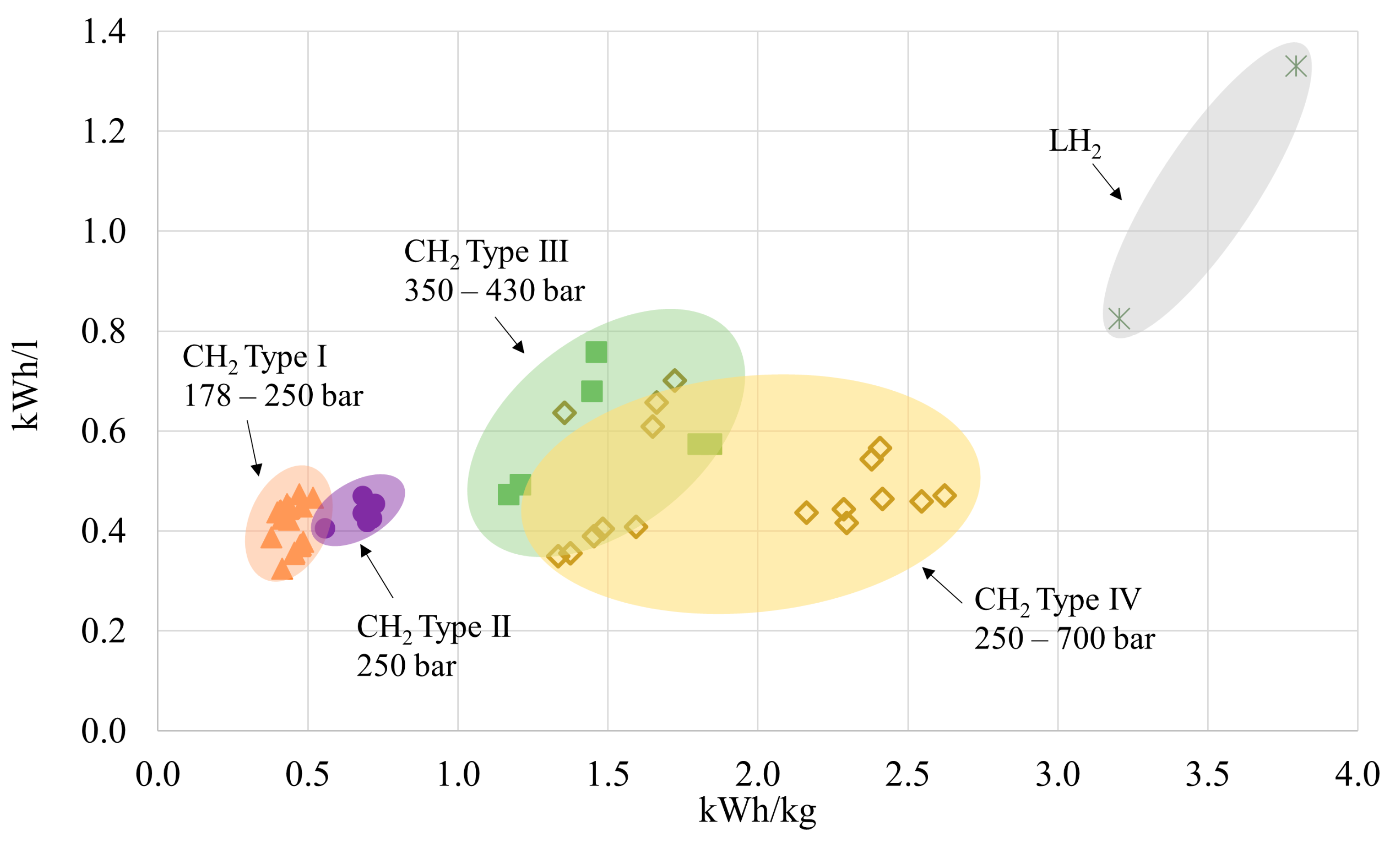
| I | All-metal, usually austenitic steels or aluminium alloys | ≤300 | 0.3 ÷ 0.5 | 0.3 ÷ 0.6 | 83 | ++ |
| II | Load-bearing metal liner hoop wrapped with resin-impregnated filament | ≤700 | 0.4 ÷ 0.5 | 0.5 ÷ 0.8 | 86 | + |
| III | Non-load-bearing metal liner axial and hoop wrapped with resin-impregnated filament | ≤700 | 0.3 ÷ 0.8 | 1.1 ÷ 1.9 | 700 | − |
| IV | Non-load-bearing non-metal liner axial and hoop wrapped with resin-impregnated filament | ≤1000 | 0.3 ÷ 0.7 | 1.4 ÷ 2.7 | 600–700 | −− |
| H2 Storage Type | Storage Pressure (bar) | T (K) | H2 Content (%wt) | Energy Density (kWh/L) | Cost Range (EUR/kg) | Remarks | Refs. |
|---|---|---|---|---|---|---|---|
| CH2 | 200–1000 | 293 | 100 | 0.3–0.8 | 0.9–8.4 | In total, 10% energy loss in the compression process. Limited energy density, suitable only for short-range shipping. | [28,30,31,32,33,34,35,36,37,38,103,104] |
| LH2 | 1–12 | 20 | 100 | 2.3 | 2.4–9.9 | Up to 40% energy loss in the liquefaction process. Limited availability. Suitable for medium–long-range shipping. Boil-off management required. | [12,31,103,104] |
| CcH2 | 150–350 | 40–80 | 100 | 2.6 (@38 K and 300 bar) | 2.4–9.9 | Requires strict insulation. Suitable for medium–long-range shipping. | [31,103,104] |
| MH | 20–150 | 260–425 | >8 | 35–40 | 0.5–8 * | Requires thermal management. Could be coupled with heat recovery from PEMFCs. | [28,72,103] |
| LOHC | 1 | 293 | 6–7 | 2 | <1 ** | Highly endo/exothermal processes. Large volumes required on board. PEMFC poisoning with current technology for dehydrogenation. | [28,94,98] |
| NH3 | 10–17 | 293 | 17.6 | 3–4 | 0.7–0.8 ** | Suitable for medium–long-distance shipping. Requires cracking process to obtain hydrogen for feeding PEMFCs. Typical cracker efficiency 75%. Main issues: toxic substance, possible poisoning of PEMFCs if no adequate hydrogen purification. | [84,86,94] |
| LNG | 1–1.2 | −162 | 25 | 6–7 | 0.4–0.5 ** | Reforming process required for obtaining hydrogen to feed PEMFCs. Typical reformer efficiency 75%. Main issues: zero emission is not guaranteed, methane slip, PEMFC CO poisoning. | [10] |
| MeOH | 1–81 | 293 | 12 | 3.64–3.92 | 0.4–1.2 ** | Possible to use directly in HT-PEMFCs. For the use in LT-PEMFCs, reforming is required (efficiency 75%). No zero emissions, PEMFC CO poisoning. | [83,94,104] |
| Hybrid Powertrain Architecture | Configuration | Legend | |
|---|---|---|---|
| Series |  |  | DC/DC Converter |
 | AC/DC Inverter | ||
 | Electric generator | ||
 | Electric motor | ||
 | DC bus | ||
 | Shaft | ||
| Parallel |  | ||
| Series-parallel |  | ||
| LHV Maximum Design Efficiency (%) | Investment Cost (EUR/kW) | Lifetime (Operating Hours) | Refs. |
|---|---|---|---|
| 50–55 | 830–2500 | 2000–10,000 | [22,121,122] |
| ESS | Energy Density (Wh/kg) | Power Density (W/kg) | Capital Cost (EUR/kWh) | Life (Cycles) | Marine Applications (-) | Refs. | |
|---|---|---|---|---|---|---|---|
| LIB | NMC | 150–220 | 520 | 475–960 | 1000–12,000 | Currently the most largely used type of LIB in shipping, especially thanks to adjustable power and energy density. | [123,131,132,134] |
| LFP | 90–120 | 200 | 475–960 | 1000–12,000 | Relatively low specific energy but good safety feature and resiliency to temperature characteristics; together with NMC is among the most largely used LIB in shipping. | [123,134] | |
| LTO | 50–80 | 70 | 960–1920 | 6000–20,000 | Suitable especially for applications where high power or large number of cycles are required. | [123,130,134] | |
| SC | 0.01–15 | 500–5000 | 96–475 * | >500,000 | Suitable for applications where high power density is needed but low energy capacity is required, e.g., offshore drilling unit. | [123,133,134] | |
| Ref. | Authors | Year | EMS Proposed | Degradation Considered | ||
|---|---|---|---|---|---|---|
| Rule-Based | Optimization-Based | PEMFC | ESS | |||
| [20] | Han, J., et al. | 2014 | ● | ○ | ○ | ○ |
| [164] | Zhu, L., et al. | 2014 | ● | ○ | ○ | ○ |
| [163] | Bassam A.M., et al. | 2016 | ● | ○ | ● | ● |
| [176] | Bassam A.M., et al. | 2017 | ● | ○ | ● | ● |
| [165] | Tang, D., et al. | 2017 | ○ | ● | ○ | ○ |
| [166] | Rivarolo, M., et al. | 2018 | ○ | ● | ○ | ○ |
| [167] | Chen, H., et al. | 2020 | ○ | ● | ○ | ● |
| [172] | Hasanvand, S., et al. | 2020 | ○ | ● | ○ | ● |
| [168] | Letafat, A., et al. | 2020 | ○ | ● | ○ | ○ |
| [169] | Rivarolo, M., et al. | 2020 | ○ | ● | ○ | ○ |
| [33] | Taccani, R., et al. | 2020 | ● | ○ | ○ | ○ |
| [173] | Vafamand, N., et al. | 2020 | ○ | ● | ○ | ○ |
| [110] | Wu, P., et al. | 2020 | ○ | ● | ● | ● |
| [174] | Zhang, Z., et al. | 2020 | ○ | ● | ● | ● |
| [17] | Balestra, L., et al. | 2021 | ● | ○ | ● | ● |
| [21] | Balestra, L., et al. | 2021 | ● | ○ | ● | ○ |
| [170] | Banaei, M., et al. | 2021 | ○ | ● | ○ | ● |
| [16] | Dall’Armi, C., et al. | 2021 | ● | ○ | ○ | ○ |
| [22] | Pivetta, D., et al. | 2021 | ○ | ● | ● | ● |
| [23] | Dall’Armi, C., et al. | 2021 | ○ | ● | ● | ● |
| [171] | Dall’Armi, C., et al. | 2021 | ○ | ● | ● | ● |
| [18] | Wu, P., et al. | 2021 | ○ | ● | ● | ● |
| [19] | Wu, P., et al. | 2021 | ○ | ● | ● | ● |
| Institution | Document | Year | Notes | Refs. |
|---|---|---|---|---|
| Fuel cells | ||||
| ABS | Guide for fuel cell power systems for marine and offshore applications | 2019 | \ | [185] |
| BV | Ships using Fuel cells | 2022 | \ | [186] |
| DNV-GL | Rules for classification of ships: Part 6 Ch. 2 Sec. 3 Fuel cell installation—FC | 2019 | \ | [187] |
| KS | Guidance for fuel cell systems on board of ships | 2015 | \ | [188] |
| Batteries and ESS | ||||
| ABS | Guide for the use of lithium batteries in the marine and offshore industries | 2022 | \ | [189] |
| BV | Rules for classification of steel ships | 2021 | Pt. F Ch. 11 Sec. 22, Electric hybrid | [190] |
| DNV-GL | Rules for classification of ships | 2019 | Pt. 6, Ch. 2 Sec. 1, Battery power | [187] |
| LR | Large battery installations | 2015 | \ | [181] |
| Standard Number/Series | Title | Year | Notes |
|---|---|---|---|
| PEMFC and hydrogen technologies | |||
| ISO/TC 197 | Hydrogen technologies | n.a. | Cover hydrogen production, storage, transportation, measurement, and use. Note yet used in the maritime sector, but packages under development (ISO 19885 series) on hydrogen fuelling could be useful for bunkering of maritime vessels. Packages of ISO/TC 197 considered particularly relevant also for maritime applications are reported in the following lines. |
| ISO 19880 | Gaseous hydrogen—Fueling stations | 2020 (Pt.1) 2018 (Pt.3) 2019 (Pt.5) u.d. (Pt.6) 2019 (Pt.8) | Part of ISO/TC 197. Part 1 (General requirements). Part 3 (Valves). Part 5 (Dispenser hoses and hose assemblies). Part 6 (Fittings). Part 8 (Fuel quality control). |
| ISO 16110 | Hydrogen generators using fuel processing technologies | 2007 (Pt.1) 2010 (Pt.2) | Part of ISO/TC 197. Part 1 (Safety). Part 2 (Test methods for performance). |
| ISO/TR 15916 | Basic considerations for the safety of hydrogen systems | 2018 | Part of ISO/TC 197. Includes considerations on hydrogen embrittlement, material compatibility, low-temperature hydrogen effects on materials. |
| ISO 26142 | Hydrogen detection apparatus—Stationary applications. | 2010 | Part of ISO/TC 197. Standard intended to be used for certification purposes. Covers hydrogen detection apparatus, useful for the requirements in terms of hydrogen leaks detection. |
| ISO 14687 | Hydrogen fuel—product specification | 2019 | Part of ISO/TC 197. Part 3 (Proton exchange membrane (PEM) fuel cell applications for stationary appliances). |
| ISO 19881 | Gaseous hydrogen—Land vehicle fuel containers | 2018 | Part of ISO/TC 197. Referred to compressed hydrogen cylinders for land vehicles. Volume up to 1000 L and pressure up to 70 MPa. Only cylinders permanently attached to the vehicles are addressed. |
| ISO 19882 | Gaseous hydrogen—Thermally activated pressure relief devices for compressed hydrogen vehicle fuel containers | 2018 | Part of ISO/TC 197. Minimum requirements for pressure relief devices of hydrogen vehicles compliant with ISO 19881, IEC 62282-4-101, ANSI HGV 2, CSA B51 Part 2, EC79/EU406, SAE J2579, or the UN GTR No. 13. |
| ISO 19884 | Gaseous hydrogen—Cylinders and tubes for stationary storage | u.d. | Part of ISO/TC 197. Information can also be found at the previously available ISO 15399:2012—“Gaseous hydrogen. Cylinders and tubes for stationary storage” for cylinders and tubes up to 110 MPa, 10,000 L. |
| IEC 62282 | Fuel cell technologies | n.a. | IEC 62282-2-100:2020 “Fuel cell modules—Safety” IEC 62282-3-100:2019 “Stationary fuel cell power systems—Safety” IEC 62282-3-200:2015 “Stationary fuel cell power systems—Performance test methods” IEC 62282-3-300:2012 “Stationary fuel cell power systems—Installations” IEC 62282-3-400:2016 “Small stationary fuel cell power systems with combined heat and power output” IEC 62282-7-1:2017 “Single cell test methods for polymer electrolyte fuel cell (PEFC)” IEC 62282-8-101:2020 “Energy storage systems using fuel cell modules in reverse mode” |
| IEC 60050-485 | International Electrochemical Vocabulary (IEV)—Part 485: Fuel cell technologies. | 2020 | Replaces the withdrawn IEC 62282-1:2013 “Terminology”. |
| ISO/TC 220 | Cryogenic vessels | n.a. | Land-based cryogenic vessels (vacuum or non-vacuum). Could be useful for the maritime as it addresses also design and safety of the cryogenic vessels, gas/materials compatibility, insulation, operational requirements. Packages of ISO/TC 220 also considered particularly relevant for maritime applications are reported in the following lines. |
| ISO 20421 | Cryogenic vessels—Large transportable vacuum-insulated vessels | 2019 (Pt.1) 2017 (Pt.2) | Part of ISO/TC 220. Part 1 (Design, fabrication, inspection and testing). Part 2 (Operational requirements). Static vessels regulation available in ISO 21009. |
| ISO 21011 | Cryogenic vessels—Valves for cryogenic service | 2008 | Part of ISO/TC 220. Manufacturing and tests of valves for rated temperatures < −40 °C. |
| ISO 21029 | Cryogenic vessels—Transportable vacuum insulated vessels of not more than 1000 L volume | 2018 (Pt. 1) 2015 (Pt. 2) | Part of ISO/TC 220. Part 1 (Design, fabrication, inspection, and tests). Part 2 (Operational requirements). |
| ISO 24490 | Cryogenic vessels—Pumps for cryogenic service. | 2016 | Applicable to centrifugal pumps but could be applied also to other types of cryogenic pumps, e.g., reciprocating pumps. |
| ISO/TC 58 | Gas cylinders | n.a. | Technical committee for the standardization of gas cylinders. Of relevance for hydrogen cylinders is the package ISO 11114. |
| ISO 15649 | Petroleum and Natural gas industry | 2001 | Often used as a guidance in hydrogen piping systems. |
| UNI EN 13480 | Industrial metallic piping | 2020 | Specifies design and calculation methods for industrial piping systems and relative supports. |
| ISO 23273 | Fuel cell road vehicles—Safety specifications—Protection against hydrogen hazards for vehicles fuelled with compressed hydrogen | 2013 | Part 2 (Protection against hydrogen hazards for vehicles fuelled with compressed hydrogen). Part 3 (Protection of persons against electric shock, etc.). |
| NFPA 2 | Hydrogen Technologies Code | 2016 | Fundamentals for generation, installation, storage, piping, use, and handling of compressed and cryogenic hydrogen. |
| NFPA 55 | Compressed Gases and Cryogenic Fluids Code | 2020 | Guidelines for protection against physiological, explosive, over-pressurization, and flammability hazards associated with compressed and cryogenic gases. |
| NFPA 221 | Standard for High Challenge Fire Walls, Fire Walls, and Fire Barrier Walls | 2021 | Prescriptions for design and construction of fire protection structures for use in protecting life and property from fire. |
| NFPA 853 | Standard for the Installation of Stationary Fuel Cell Power Systems | 2020 | Related to stationary systems, provides fire prevention and proception measures for the safeguarding of life and buildings. |
| SAE J2578 | Recommended Practice for General Fuel Cell Vehicle Safety | 2014 | Related to the design, construction, operation, and maintenance of fuel cell vehicles. |
| SAE J2579 | Standard for Fuel Systems in Fuel Cell and Other Hydrogen Vehicles | 2018 | Design, construction, operational, and maintenance requirements of hydrogen fuel storage and handling systems (road vehicles). |
| SAE J2600 | Compressed Hydrogen Surface Vehicle Fueling Connection Devices | 2015 | Design and testing of fuelling connectors, nozzles, and receptacles. |
| SAE J2601/2 | Fuelling Protocol for Gaseous Hydrogen Powered Heay Duty Vehicles | 2014 | Independent document from SAE J2601 related to light-duty vehicles. Provides performance requirements for hydrogen-dispensing systems for heavy-duty vehicles with hydrogen storage pressures up to 35 MPa. |
| EN 1626 | Cryogenic vessels—Valves for cryogenic service | 2008 | Design, fabrication, and testing of valves for cryogenic use. Valid for valves diameters up to DN150. |
| EN 60079 | Explosive atmosphere | n.a. | Regulation series for explosive atmospheres (ATmosphere EXplosive—ATEX). |
| Batteries and ESS | |||
| EN 50110 | Operation of electrical installations | 2013 | Part 1—General requirements (documentation for batteries and electrical testing). |
| IEC 61508 | Functional safety of electrical/electronic/programmable electronic safety-related systems | 2010 | \ |
| IEC 61511 | Safety instrumented systems for the process industry sector | 2016 (2017 amd.) | Amendment 1: 2017. Prescription on requirements for specification, design, installation, operation, and maintenance of Safety Instrumented Systems (SIS). |
| IEEE 45 | Recommended practice for electrical installation on shipboard | 2017 (Pt.1) 2020 (Pt.2) | Part 1 (Design of electrical power generation, distribution, propulsion, loafs systems, and equipment on merchant, commercial, and naval vessels). Part 2 (Controls, control applications, control apparatus, automation on shipboards). |
| IEC 62619 | Secondary cells and batteries containing alkaline or other non-acid electrolytes—Safety requirements for secondary lithium cells and batteries, for use in industrial applications | 2017 | Requirements and tests or safe operation of secondary lithium cells and batteries in industrial applications, including marine applications. |
| IEC 62620 | Secondary cells and batteries containing alkaline or other non-acid electrolytes—Secondary lithium cells and batteries for use in industrial applications | 2014 | Marking, tests, and requirements of secondary lithium cells and batteries in industrial applications, including marine applications. |
| DOT/UN 38.3 | UN Manual of tests and criteria, Transport of Dangerous goods | 2019 | Chapter on lithium metal and lithium-ion batteries. |
| IEC 62281 | Safety of primary and secondary lithium cells and batteries during transport | 2019 (2021 amd.) | Test methods and requirements for batteries (rechargeable and non-rechargeable) for safety during transport. |
| UL 9540 | Energy storage systems and equipment | 2020 | Safety standard for grid connected or standalone ESS (battery system safety, fire detection and suppression, environmental performance, etc.). |
| IEC 60529 | Degrees of protection provided by enclosures (IP Code) | 2020 | \ |
| IEC 60092 | Electrical installations in ships | 2022 | Part 504: Special features—control and instrumentation. |
| IEC 62061 | Safety of machinery—Functional safety of safety-related control systems. | 2021 | Year 2021 version still not harmonized. The harmonized version is still the one of 2015. |
Disclaimer/Publisher’s Note: The statements, opinions and data contained in all publications are solely those of the individual author(s) and contributor(s) and not of MDPI and/or the editor(s). MDPI and/or the editor(s) disclaim responsibility for any injury to people or property resulting from any ideas, methods, instructions or products referred to in the content. |
© 2023 by the authors. Licensee MDPI, Basel, Switzerland. This article is an open access article distributed under the terms and conditions of the Creative Commons Attribution (CC BY) license (https://creativecommons.org/licenses/by/4.0/).
Share and Cite
Dall’Armi, C.; Pivetta, D.; Taccani, R. Hybrid PEM Fuel Cell Power Plants Fuelled by Hydrogen for Improving Sustainability in Shipping: State of the Art and Review on Active Projects. Energies 2023, 16, 2022. https://0-doi-org.brum.beds.ac.uk/10.3390/en16042022
Dall’Armi C, Pivetta D, Taccani R. Hybrid PEM Fuel Cell Power Plants Fuelled by Hydrogen for Improving Sustainability in Shipping: State of the Art and Review on Active Projects. Energies. 2023; 16(4):2022. https://0-doi-org.brum.beds.ac.uk/10.3390/en16042022
Chicago/Turabian StyleDall’Armi, Chiara, Davide Pivetta, and Rodolfo Taccani. 2023. "Hybrid PEM Fuel Cell Power Plants Fuelled by Hydrogen for Improving Sustainability in Shipping: State of the Art and Review on Active Projects" Energies 16, no. 4: 2022. https://0-doi-org.brum.beds.ac.uk/10.3390/en16042022