
As-Textured As-Built BIM Using Sensor Fusion, Zee Ain Historical Village as a Case Study


1
Department of Conservation Science, Queen Rania Faculty of Tourism and Heritage, The Hashemite University, P.O. Box 330127, Zarqa 13133, Jordan
2
Geomatics Department, Architecture and Planning Faculty, King Abdulaziz University, Jeddah 21589, Saudi Arabia
*
Author to whom correspondence should be addressed.
Remote Sens. 2021, 13(24), 5135; https://0-doi-org.brum.beds.ac.uk/10.3390/rs13245135
Submission received: 17 November 2021
/
Revised: 6 December 2021
/
Accepted: 14 December 2021
/
Published: 17 December 2021
(This article belongs to the Special Issue Photogrammetry and Remote Sensing for Survey and 3D Reconstruction of Historical Built Landscapes)
Abstract
:The work described in the paper emphasizes the importance of integrating imagery and laser scanner techniques (TLS) to optimize the geometry and visual quality of Heritage BIM. The fusion-based workflow was approached during the recording of Zee Ain Historical Village in Saudi Arabia. The village is a unique example of traditional human settlements, and represents a complex natural and cultural heritage site. The proposed workflow divides data integration into two levels. At the basic level, UAV photogrammetry with enhanced mobility and visibility is used to map the ragged terrain and supplement TLS point data in upper and unaccusable building zones where shadow data originated. The merging of point clouds ensures that the building’s overall geometry is correctly rebuilt and that data interpretation is improved during HBIM digitization. In addition to the correct geometry, texture mapping is particularly important in the area of cultural heritage. Constructing a realistic texture remains a challenge in HBIM; because the standard texture and materials provided in BIM libraries do not allow for reliable representation of heritage structures, mapping and sharing information are not always truthful. Thereby, at the second level, the workflow proposed true orthophoto texturing method for HBIM models by combining close-range imagery and laser data. True orthophotos have uniform scale that depicts all objects in their respective planimetric positions, providing reliable and realistic mapping. The process begins with the development of a Digital Surface Model (DSM) by sampling TLS 3D points in a regular grid, with each cell uniquely associated with a model point. Then each DSM cell is projected in the corresponding perspective imagery in order to map the relevant spectral information. The methods allow for flexible data fusion and image capture using either a TLS-installed camera or a separate camera at the optimal time and viewpoint for radiometric data. The developed workflows demonstrated adequate results in terms of complete and realistic textured HBIM, allowing for a better understanding of the complex heritage structures.
1. Introduction
Recently, BIM applications in heritage have been identified in a variety of areas, including conservation and restoration activities [1,2,3], structural analysis and monitoring [4,5,6], facility management [7,8,9], virtual and augmented reality (VR) [10,11], etc. However, implementing BIM in the field of heritage is a difficult task since parametric objects in BIM software libraries are incapable of adapting to the morphological irregularities that are common in historic buildings [12]. This can only be achieved by providing new features and materials for more adaptive BIM libraries. Such features require precise recording and detailed surveys that can be appropriately interpreted and modeled on the BIM platform [13]. Modern 3D survey techniques, such as terrestrial laser scanning (TLS) and photogrammetry, were recently proposed in different lectures as possible methods for reconstructing heritage geometry in BIM, the remotely sensed point cloud acquisition technique called Scan-to-BIM [14,15,16,17].
While much emphasis has been placed on improving the quality and quantity of HBIM input data, 3D laser scanning remains the best technology for delivering high-resolution scans in real time [18,19]. The scanner either uses the time-of-flight (TOF) concept or measures the waveform between emitted and returned signals to calculate the distance between the scanner and the scene surface. Due to the object’s shape, scale, and occlusion, several scans from different positions are frequently required to cover the whole surface area [20]. The data processing step begins with the alignment of scans into a single reference system to produce a unified point cloud of the entire site. The registration of scans is typically performed manually or automatically in pairs using targets or homologue features. After the alignment, the redundant data from overlapping scans and the potential errors caused by the device’s position and signal reflection in certain materials, such as gilded facades, should be removed [21]. Then, a polygonal model is built from the point clouds to create the best graphic representation of the scene. Many terrestrial laser scanner systems can simultaneously collect high-resolution digital photographs via a mounted camera. Color data extracted from the images are applied to the point cloud. Color data acquired by terrestrial scanners may not always be of adequate quality, and the ideal conditions for their use may not always be compatible with the positioning of scanners [22]. Regardless of the previous TLS’s potential, the data produced by these technologies cannot be used solely for complete 3D modeling of historical applications [23]. Complexity of some elements, self-occlusions, or gaps in surveying might all provide challenges. Missing parts, such as roofs, upper parts, and slope surfaces of a monument, may result from the lack of high platforms for a higher location of data acquisition [24]. Furthermore, transportability and accessibility problems occur in certain field campaigns conducted in rugged terrain [25].
This is where photogrammetry can help. Image-based 3D reconstruction technology is cost effective, flexible, fast, and capable of producing accurate models of complex objects in terms of point density and quality [26]. The data could be collected using portable cameras or cameras attached to an unmanned aerial vehicle (UAV) [27]. With recent advancements in photogrammetry algorithms and computer vision automated methods, the processing pipeline has developed into a robust and valuable solution for 3D reconstruction [28]. The main challenge with the available automated software is the significant constraints on the quality of required images and camera network [29]. The use of a UAV nadir photo network for 2D objects (such as roofs) is fairly straightforward because only a few requirements must be met, which frequently include the percentage of imagery overlaps and ground sample distances (GSDs). When dealing with 3D objects that need a convergent network with oblique photographs (such as building facades), the problem becomes considerably more challenging [30]. Imaging scaling, inclination angle, shadow, and lighting variations can all have an impact on metric quality [31,32]. Combining TLS and photogrammetric techniques to overcome the bottlenecks of each proved to be the most effective way to record the geometry of large and complex heritage sites for accurate HBIM applications [33,34,35].
In addition to the correct geometry, texture mapping is particularly important in the area of cultural heritage [36]. Texture can represent the structure condition, decay of the material, decorative variety, and phases of rebuilding. Additionally, color image information is also indispensable for features such as frescos, decorative elements, and mosaics, and considered as a requirement application for visualization and animation purposes [37]. This is not an issue with current BIM platforms because the primary objective is to manage a new structure, so visual effects are less important. Texturing in HBIM parametric modeling is often addressed by either using standard texture provided by the software [38,39] or by customized texture based on object images [40]. Others store the images or orthophoto with BIM surfaces as complementary data to support heritage conservation [41]. Different research discussed mapping the material component and decay in BIM environment using a color legend [42,43,44]. A photogrammetric survey was also carried out to produce 3D orthophotos from the collected images block; the results are attached to the HBIM as the basis for a detailed analysis of the related portion of the building [45]. Banfi et al. [46] also proposed a BIM texture method in extended reality (XR) environment derives from synchronization of multiple modeling software. The method requires the use of several immersive photogrammetric photos, and UV mapping was used to address the problem of representing a texture in 3D rendering.
Hence, the article proposed As-Textured As-Built BIM workflow using multi-sensor survey combines TLS with UAV and close-range photogrammetry. The proposed workflow, depicted in Figure 1, was approached during the recording of Zee Ain Historical Village in Saudi Arabia. The village has been nominated for involvement in the UNESCO World Heritage list and represents an important example of complex natural and historical heritage. As a result, advanced 3D modeling skills are required to have the accurate geometrical and morphological data during the digitization process. TLS data is complemented with a carefully designed nadir and convergent UAV camera network with abundant GCPs to ensure complete coverage of the village topography, roofs, and inaccessible facades. Both datasets were registered using the ICP algorithm and georeferenced using the Ain al bed’s local coordinate. The registered point cloud was then used to improve the digitization of the geometry in the BIM environment by including complete mapping information. The article also proposed a method for efficient texture mapping of HBIM using orthophoto produced from the laser scanner camera or an independent camera which captured the imagery at optimum time and place for spectral information. The procedure entails sampling 3D points in a regular grid, with each cell uniquely associated to the model point, then the registered images are used to map the spectral information in the corresponding cell (orthophoto pixel). Data customers (e.g., engineers, architects, conservators, and virtual tourists) can benefit from warping true orthophotos at a uniform scale across the BIM geometry.
Briefly, this paper provided the following main contributions:
- Fusion of TLS and UAV photogrammetry data to enhance digitizing HBIM with complete mapping information.
- A flexible method for photorealistic texture mapping of HBIM using True orthophoto generated from laser point and close-range imagery.
- Developed digital content of Zee Ain historical village to help satisfy UNESCO’s World Heritage nomination file requirements.
The article is organized as follows: Section 2 describes the history of Zee Ain village. Section 3 discusses data collection and sensor configuration. TLS and photogrammetric data fusion are presented in Section 4. BIM implementation of the village discussed in Section 5. Section 6 discusses HBIM texture mapping with true orthophoto. Section 6 and Section 7 discuss the results and draw conclusions.
2. Zee Ain Heritage Village
Zee Ain, depicted in Figure 2, is a historical settlement on the top of a white mountain known for its agricultural products. It is approximately 20 km from the province of Al-Makhwat and 24 km from the city of Al-Baha. The ancient village is an exceptional example of a typical community that are well adapted to their surroundings as well as their social and economic functions. Land use and fortification shape the settlement and its landscape setting. The 400-year-old town was recently proposed for inclusion on the list of UNESCO World Heritage Sites. It has 49 residences, nine of them with only one floor, nineteen buildings with two floors, eleven have three floors, and ten buildings have four floors. The settlement was constructed utilizing the “Medamik” bearing wall course technology, with wall thicknesses varying from 0.7 to nearly 0.9 m and structures roofed with Sider wood. The large chambers are roofed with “Al-zafer” columns, and above the Sedir wood are mud-covered “Salat” stones. The lower levels serve as reception and living areas, while the top levels serve as bedroom areas. Some of the structures have been maintained, while others have been partially or totally demolished. The settlement is also distinguished by its permanent water supply and defensive fortress, which is encircled on three sides by mountains [47].
3. Data Collection
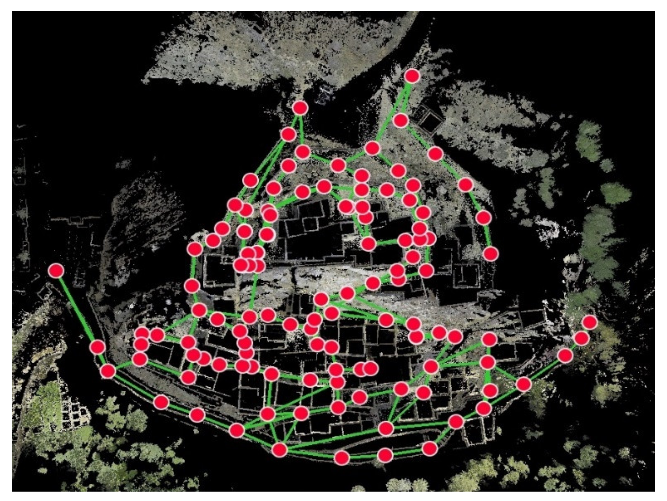
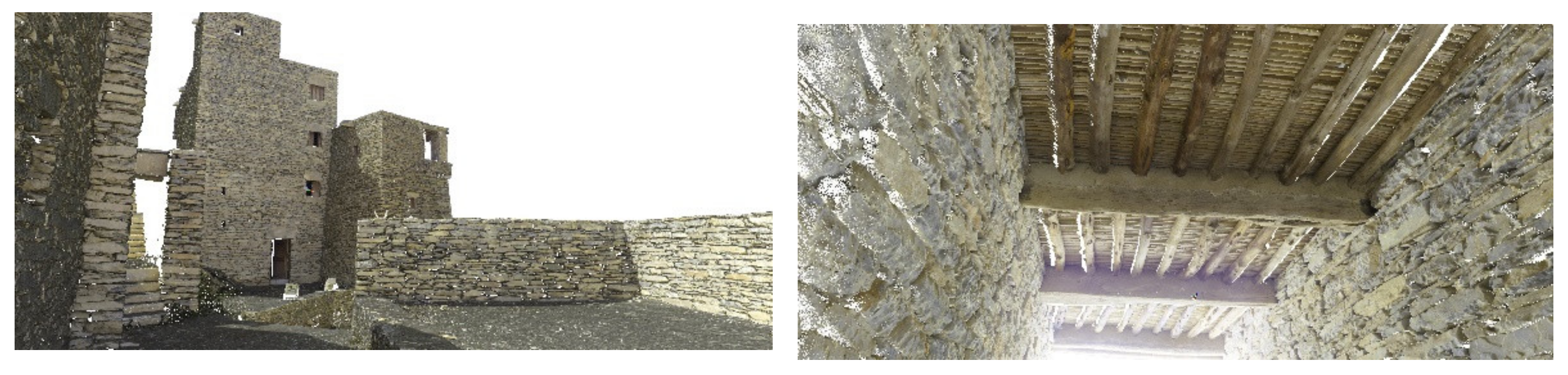
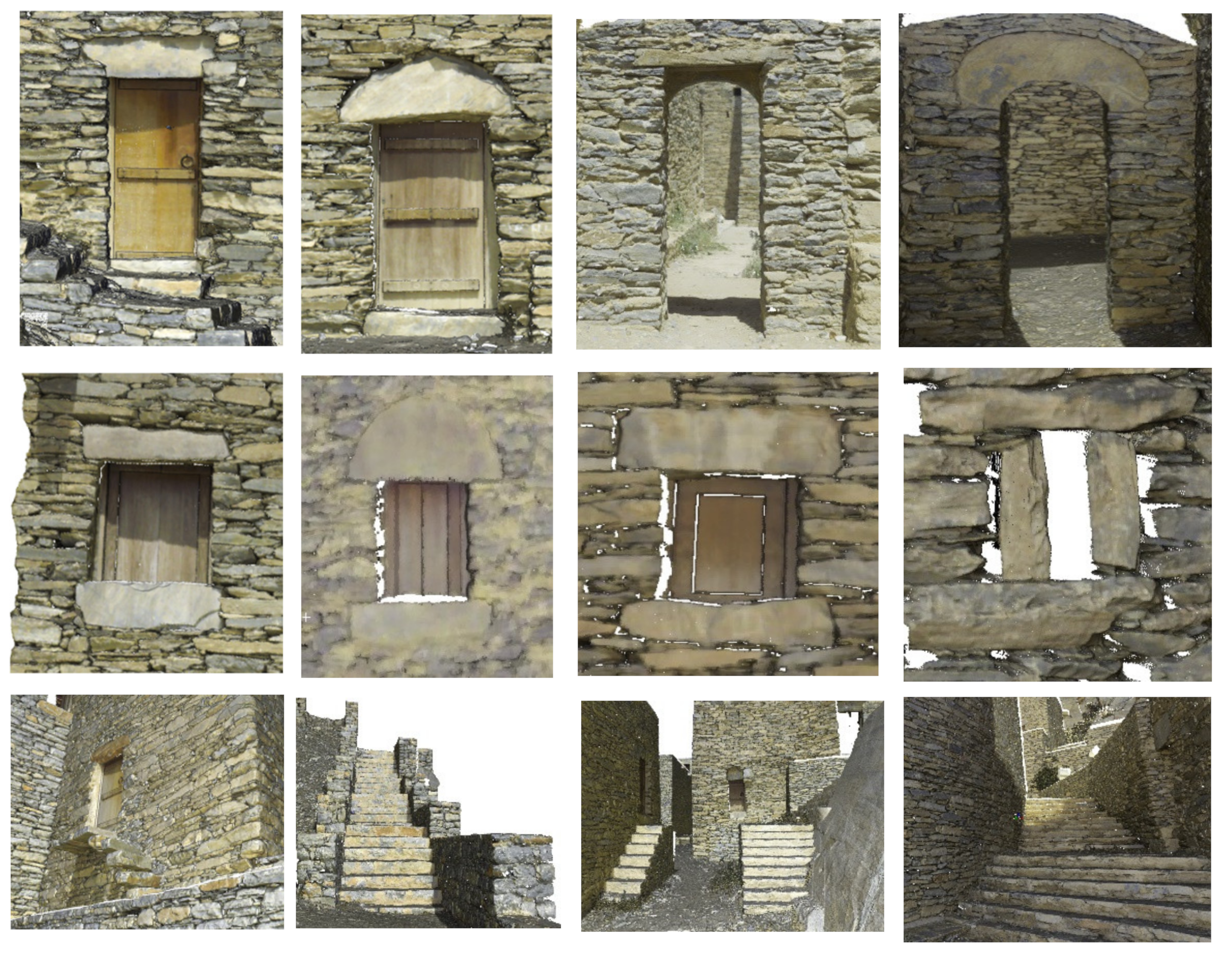
The survey of the village buildings was carried out using a TLS for the facades and a photogrammetric UAV platform for the upper part of the structures. The study area was mapped in two separate campaigns; the scanning campaign, which included the TLS position planning phase, took seven days. The UAV campaign, on the other hand, was completed in a single day. Five people were responsible for transporting the instruments and carrying out the field work. Weather was also considered during the planning process. We were looking for a clear sky. In the first campaign, the surface point clouds were acquired using a Leica RTC360 3D laser scanner. The time of flight (TOF) laser scanner with HDR image processing can measure colored point clouds at speeds of up to 2 million, ranges of 0.5 to 130 m and has a 360° × 300° field of view. The video-enhanced inertial measurement system tracks the single scanner positions in real time, enabling automated field registration without targets. The system equipped with a 36 MP camera system captures a calibrated 360° × 300° spherical image to color the produced point cloud. The work on the site was preceded by careful planning to ensure that point clouds from two adjacent sites were spatially overlapped adequately; orthoimagery on Google Earth was utilized to make a preliminary evaluation of visibility for ideal laser scanner placement. The scanner’s subsequent position took terrain roughness and accessibility into consideration. The complexity of the architectural layout requires a large number of positions to avoid occlusions in the model; the scanning work plan is depicted in Figure 3. TLS was performed from a total of 123 positions using high-density scanning. The final model, depicted in Figure 4, has 10.6 billion points. Figure 5 shows examples of interior and exterior 3D colored point clouds, while Figure 6 shows the most common architectural features of Zee Ain village. Ground Control Points (GCP) should be georeferenced using the local reference system (Ain el abed UTM 36 North). Leica GNSS Viva GS15 receivers with 3 mm + 0.5 ppm accuracy are used in conjunction with a Leica Total Station TCR 1201 (0.3 mgon, 1 mm + 1.5 ppm). Geometric leveling with a Leica Runner 24 level (double-run leveling/2.0 mm per km) was used to obtain the GCPs orthometric height.
The viability of TLS for surveying the whole structures of the village is quite limited due to the geological nature and the narrow corridors between the buildings. As shown in Figure 7, most roof and upper zone building facades are beyond the range of terrestrial scanning capabilities. For these reasons, another survey campaign was performed using UAV. The UAV-SfM approach gives a novel vertical to subvertical viewing angle, which improves mapping capacity in places of substantial vertical relief occluded from TLS and where data shadows occurred.
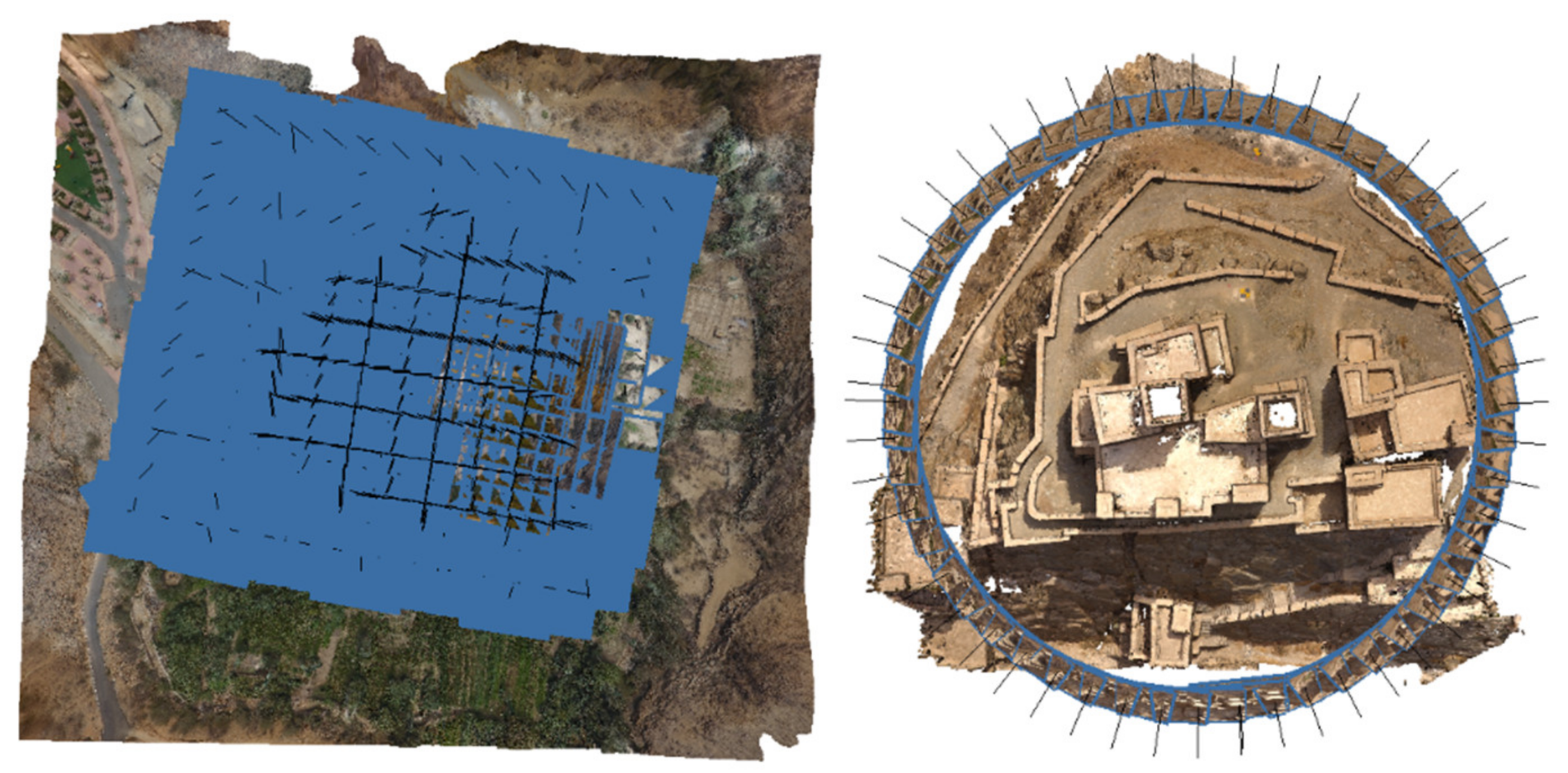
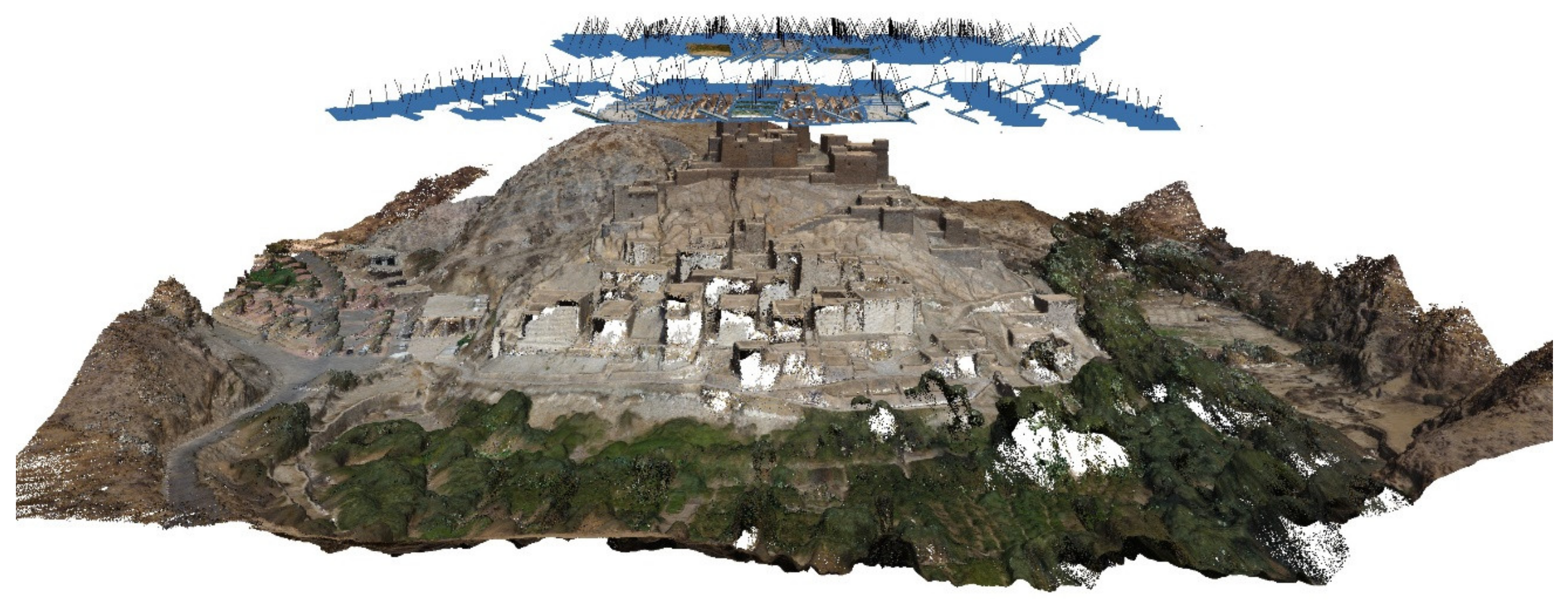
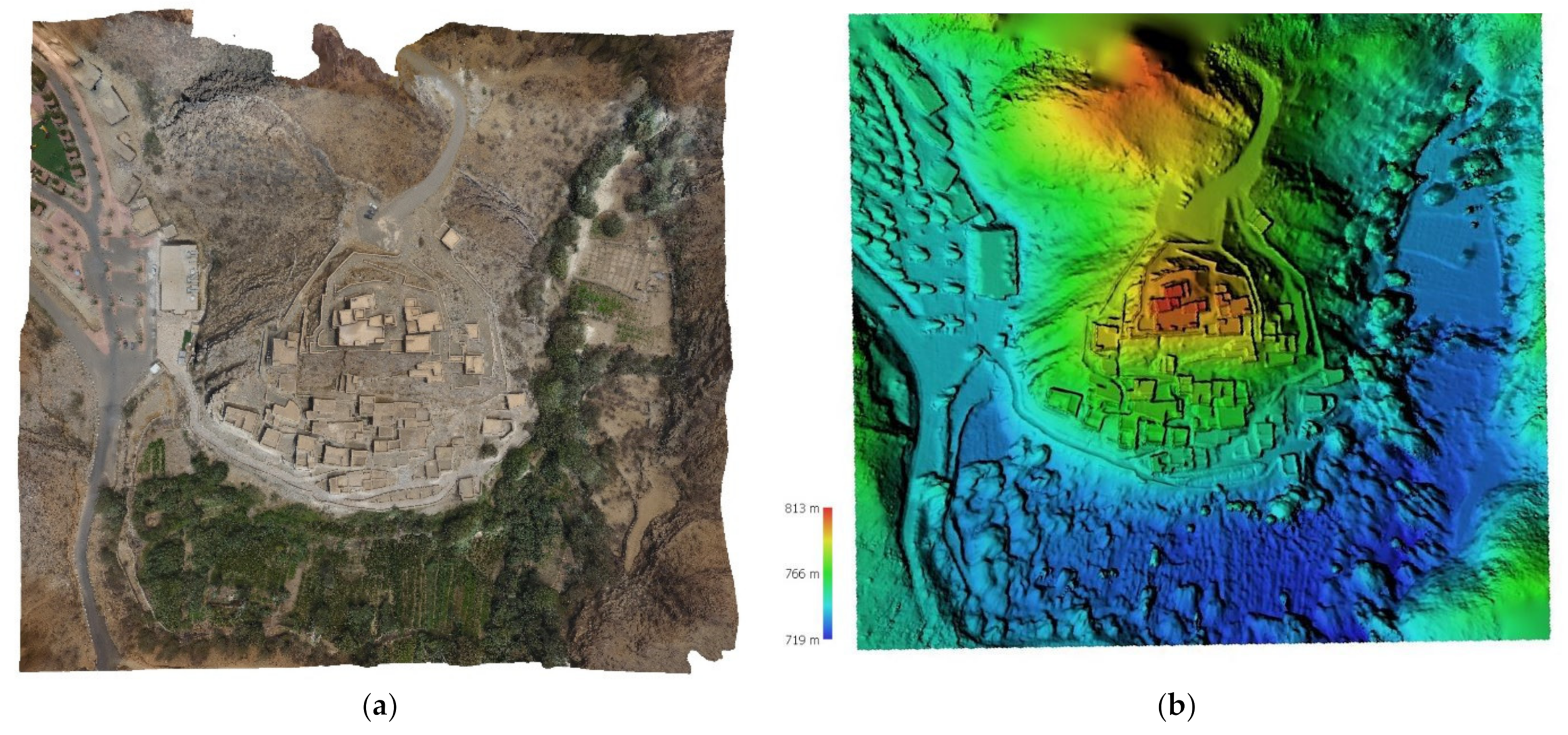
A DJI Phantom 4 multi-copter rotary wing drone (shown in Figure 8a) was used for aerial surveys. Takeoffs and landings in limited spaces are possible thanks to the rotary wings. It has a 12 Mega pixel digital camera with 35 mm focal length wide-angle lenses, weighs 1380 g, and travels at a speed of 20 m per s. The camera network and image blocks that represent the object’s geometry have a significant impact on subsequent photogrammetric processing. It is highly preferred in Zee Ain Village to create a complete 3D representation of natural and architectural heritage, which necessitates the use of both oblique and nadir imagery networks. The nadir network’s concept was to create a general map of the village and its surroundings. Images were taken with a GSD of about 3 cm covering 0.21 square km, taking into account the maximum height of the towers in the uphill areas. GCPs were used during the bundle adjustment to georeference 3D data. Figure 8b depicts the nadir camera network, which takes 712 photographs and is linked to nine ground reference points. Additional UAV images of the building were obtained at close range with oblique images to produce high-resolution photos useful for detecting façade geometry and materials, Figure 9 depicts the UAV nadir and oblique photo trajectories. The convergent camera network took 100 pictures for the interest region. The camera focal length should be fixed to facilitate bundle adjustment and self-calibration. Typically, the production pipeline is divided into different phases. First, the camera’s parameters are determined by matching the corresponding features within the overlapping regions. The bundle adjustment procedure is used to increase the precision of camera trajectory estimation, eliminate prediction errors and avoid camera tracking error accumulation. The SfM method tries to retrieve camera parameters and the scene’s sparse point cloud, then pixel wise matching is created by the dense point cloud. The image processing was carried out using Agisoft Metashape photogrammetry software; Figure 10 and Figure 11 show the 3D point cloud for both oblique and nadir image blocks. It can be seen that the missing and occluded areas of the TLS are sampled with UAV point clouds. The village photogrammetric orthophoto and Digital Surface Model (DSM) with a 6.8 cm/pixel resolution is shown in Figure 12.
4. TLS and UAV Data Fusion
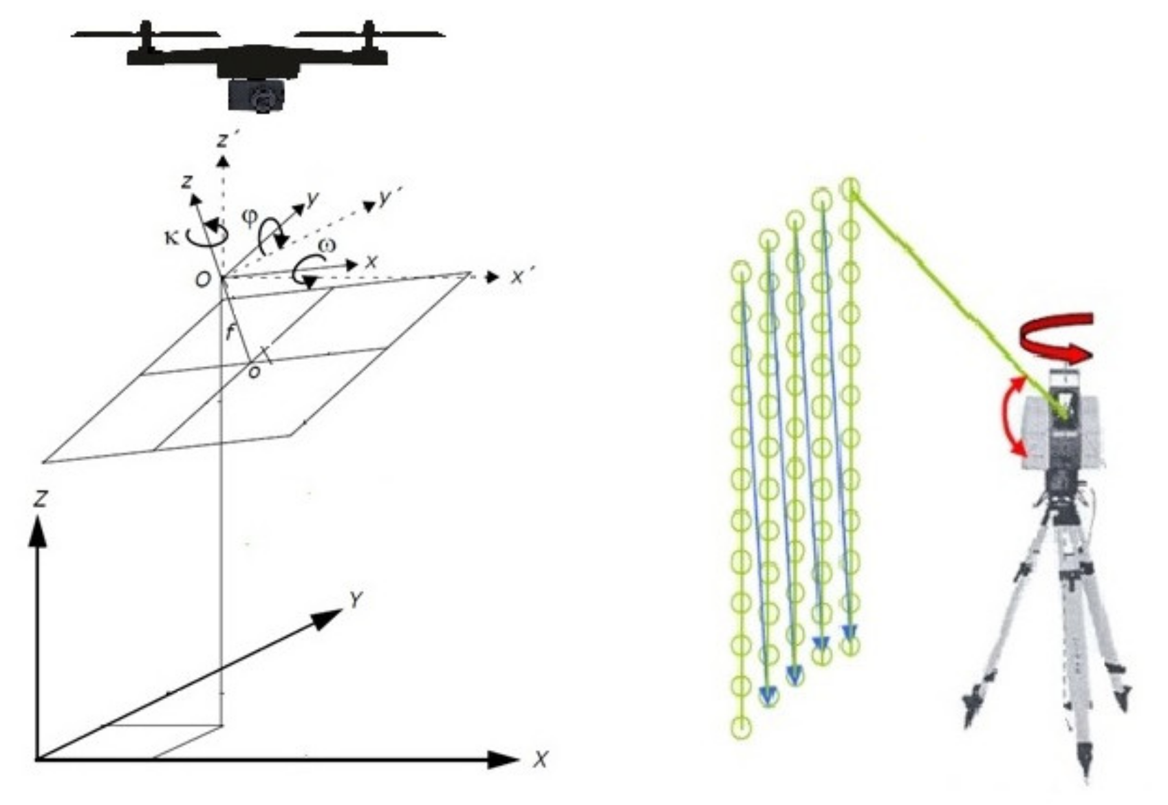
The most challenging aspect of multi-sensor data fusion is aligning and converting all point cloud data to the same coordinate system, i.e., the two datasets should be associated with the same spatial location. That is, laser scanning projects that used scanner position coordinates will be combined with the georeferenced UAV project. Besl and McKay [48] developed the Iterative Closest Point (ICP) algorithm, which is a common approach of dataset registration. The basic principle of ICP is to consider the nearest point to be a correlated point in the other cloud. It is carried out by iteratively converting and rotating a free dataset to a fixed one with six degrees of freedom until the data transformation change converges within the required tolerance. The registration form is of a non-target nature that completely automates the process. The scans, on the other hand, should be positioned in a reasonable manner for the process to converge efficiently and quickly. In this case, the corresponding points are manually identified in order to calculate the initial motion of the two clouds. The translation and rotation parameters (Tx, Ty, Tz, ω, φ, κ) between TLS coordinate systems and image models are depicted in Figure 13. The ICP can then be completed as a fine or as a local registration process. The procedure was repeated until all of the point clouds from the sensors were precisely registered. Figure 14 depicts the result of data integration, combining UAV photogrammetric data with TLS data.
5. BIM Implementation
In the BIM environment, the integrated point cloud was used for parametric modeling with the Autodesk Revit package. The HBIM model of the historical village was divided into three parts. The first part is concerned with the modeling of regular structures, such as walls, floors, roofs, towers, and stairs. The second part is concerned with developing new families, building blocks that share a common set of properties (parameters), for repetitive architectural elements such as doors and windows. In the third section, we model the environmental context and terrain, inserting utility spaces, passageways and tree masses.
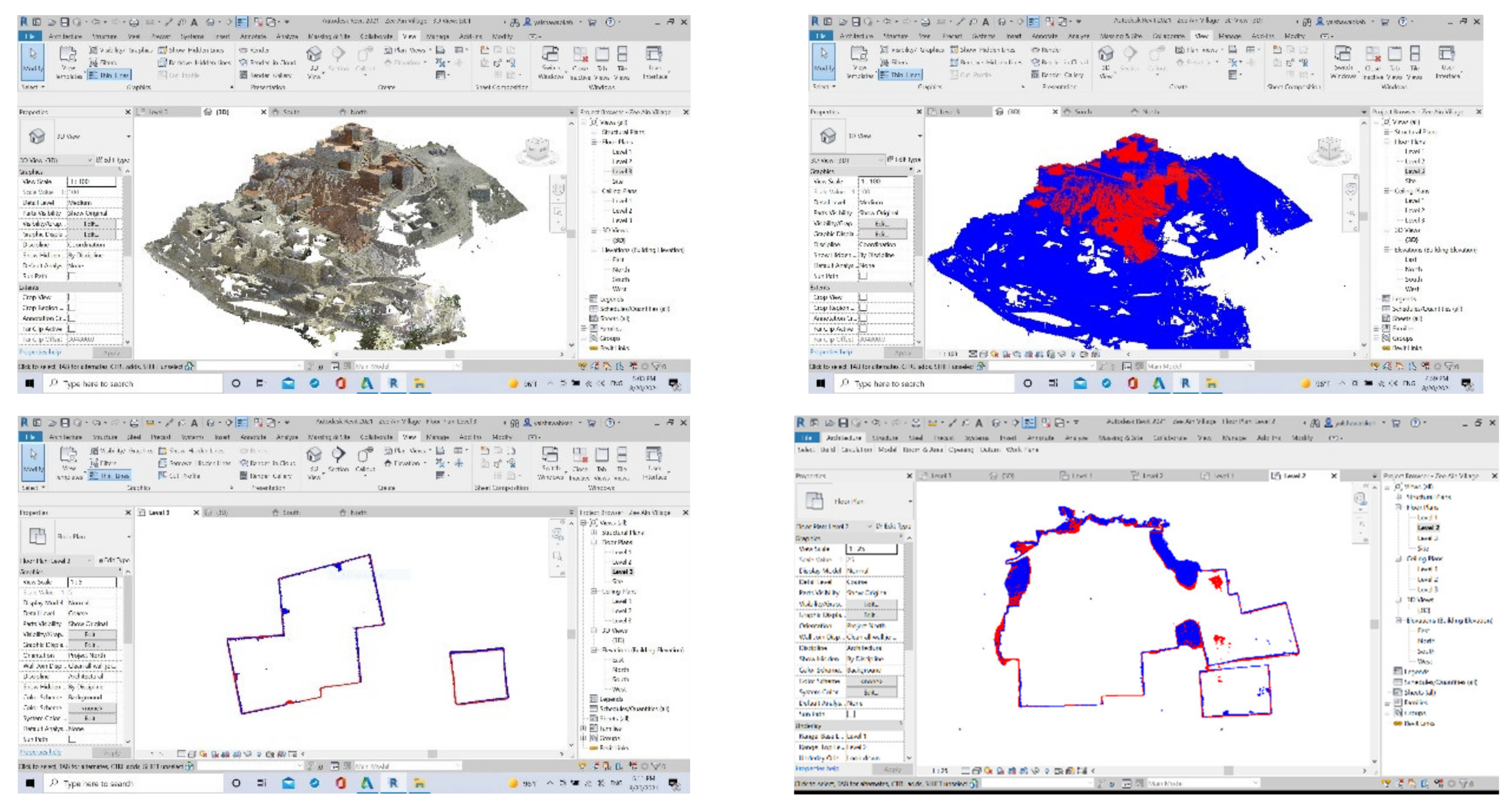
The point cloud was managed with Recap software before being converted to rcp format. The point cloud was imported into Revit while remaining in the survey’s reference system. The point cloud was segmented to provide sections and elevations as a map for finding different library objects, such as walls, towers, arches, floors, and other accessibility and interior features. The point cloud was characterized by closed polygons to be used as a guide for modeling the various regular architectural elements. It is clear that the combination of TLS and UAV point clouds provides complete geometry and enhances the digitization, tracing, and plotting of the perimeter building surfaces as depicted in Figure 15. In the tower modeling example, it was essential to incorporate length, depth, internal and external height, base dimensions, and external and upper widths in order to create the profile of the walls with the right inclination and provide the parametric function that could modify all the tower components. The thickness of the walls was determined by taking direct measurements with a tape. Another unique feature was the staircase. The investigation started with the development of the exact 3D contour of the structure and was then transformed into 3D elements for each step of the stairs, taking into consideration the height increments; the resultant model is shown in Figure 16.
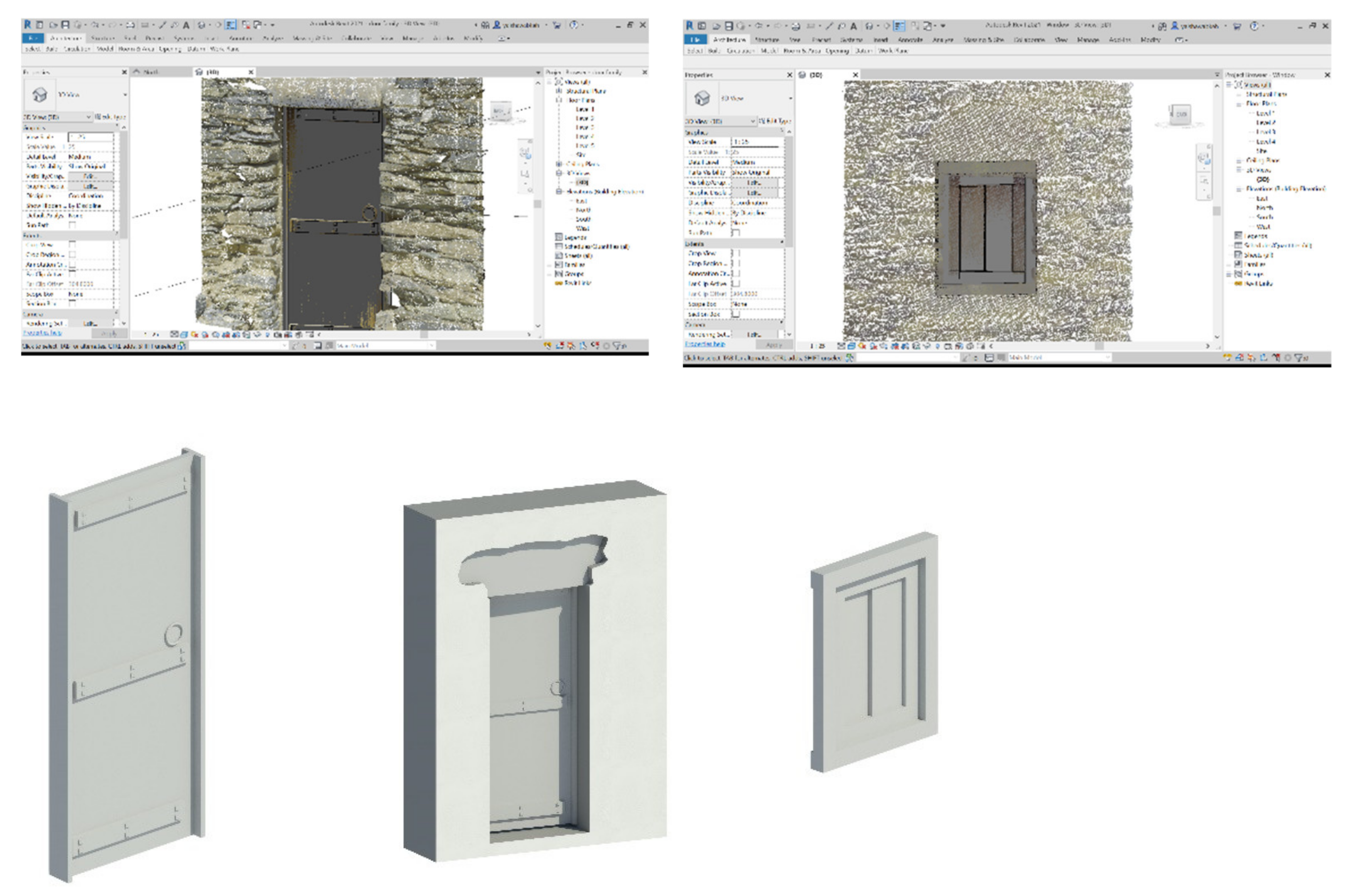
Many elements had distinct shapes that were not found in standard BIM libraries. As a result, new families for architectural elements such as doors and windows have been created. These components were modeled using the precise dimensions from the point cloud. The library was linked to the different elements’ database, thus enabling users to modify the shape of the architectural elements by adjusting the corresponding parameters. This library is regarded as a practical solution for repetitive 3D modeling of a wide range of buildings with similar forms without the need to start from scratch. It has been necessary in some cases, such as the main entrance door, to add the lintel stone above the door, as shown in Figure 17.
Aside from the structures, the surrounding topography and well-defined landscape features such as passageways, utility areas, and plants aid stakeholders in understanding a planned project and make operation management much easier [49]. High-resolution UAV data are required for modeling landscape elements and surrounding topography at the village project site. As shown in Figure 18, more than 200 thousand points of the generated DSM are imported into Revit. Because all of the data were already georeferenced, the village’s Historic Building Information Modeling was combined with geographic data (terrain and infrastructure), as shown in Figure 19.
6. As-Textured As-Built BIM
Engineers, conservators, architects, and virtual tourists will benefit greatly from an HBIM database that combines parametric geometry and color information. Texture is typically addressed in HBIM instances by either using the software’s standard texture or by creating a new customized texture based on perspective images of the object, in which case the visual effect is not realistic. Our proposed method emphasized the importance of combining laser scanning and photogrammetry in producing accurate orthophotography that can be used for realistic and reliable HBIM texturing. Texture mapping with true orthophoto at a uniform scale will provide useful information that will allow the user to position objects decay and quantify deterioration in heritage structures. Orthophotography requires the use of a reference image, a digital 3D model, and image sensor internal and external parameters. As shown in Figure 20, the method begins by transforming the TLS point data into a regular gridded Digital Surface Model (DSM) in which each cell is uniquely associated to the model point. Then, each DSM cell is projected in the corresponding perspective imagery, and the relevant color information is mapped to its associated cell in the ortho plan (orthophoto pixel).
The proposed method allows for the acquisition of input-colored images using a TLS-installed camera or images taken by an independent camera at the optimal time and viewpoint for radiometric information. While the geometry-color registration parameters are already known for the images collected from TLS camera, the registration parameters of the independent imagery with TLS model are a prerequisite for color projective. The manual method entails defining conjugate pixel-model coordinates as input data and then solving camera resection using collinearity condition equations. As shown in Figure 21, these equations are derived from the central projection of an object point via the sensor plane to the camera’s perspective center (PC). The resulting parameters are represented by a 3 × 3 rotation matrix and a translation vector within the equations (Equation (1)). The image coordinates are (xa, ya), while the object coordinates are (XA, YA, ZA). The rotation matrix elements rij are obtained from the angular parameters (ω, ɸ, ƙ). (X0, Y0, Z0) are the coordinates of the camera, c is the focal length of the camera, and (x0, y0) are the principal point coordinates.
The pixels of a source image that correspond to visible points are used to produce the true orthoimage, whereas invalid pixels that belong to the shadow (occluded area with no DSM data) are recognized and marked in white, as illustrated in Figure 22. The Figure depicts color photos acquired from a TLS-installed camera and a separate Canon EOS camera (12 Mega pixels). These images were processed to generate true orthophoto with ground sampling distance (GSD) of 1 mm used in texturing the BIM model as depicted in Figure 23. Since the orthophoto will have the same dimension as the corresponding HBIM surfaces, their warping will be accurate and reliable. Figure 24a depicts a large-scale true orthophoto (2 cm GSD) processed using TLS camera. The orthophoto was warped in HBIM of the village buildings and walls as depicted in Figure 24b. Figure 24c depicts As-Textured HBIM of the buildings using true orthophotos projected from different locations. It can be seen that some facades lack texture information. This is due to the fact that these facades are obscured from TLS stations and are unsampled, as shown in Figure 7.
7. Discussion
The key challenges in the building information modeling of existing building components are the uniqueness of their artifacts and their complexity, which has a major impact on the 3D data acquisition and organization. Historic Zee Ain Village surveys have gained access with portable and effective methods that offer broad coverage of the site. The workflow presented here combines TLS data with SFM-UAV data from oblique and nadir camera networks. The precision and completeness of the 3D model enabled the development of reliable geometry of the Building Information Modeling. HBIM was also combined with geographical data (topography and infrastructure), allowing for large-scale visualization, assessment, and management. Historical structures, as compared to newly constructed buildings, require a 3D color mapping phase to communicate their distinct structure, texture, and decorative characteristics. The textures in the BIM libraries are not always truthful and therefore sharing and mapping the information does not allow for an accurate representation of the structure. As a result, the article proposed a method for efficient HBIM texture mapping based on true orthophoto produced from the laser scanner point cloud and close-range imagery. The method is flexible because it allows images to be captured using either the TLS installed camera or an independent camera. Following the definition and evaluation of the proposed methods, it is necessary to compare their contribution to other state-of-the-art HBIM workflows.
- As stated in Section 2, several methods have been developed within the scientific community to improve the interpretation and plotting of occluded objects in laser point clouds using non-metric images [13,37]. Tracing object features in 2D images with no scale information will not ensure accurate tracing and positioning of object shapes in the corresponding laser data; instead, the proposed method identifies complex and irregular objects in the context of a scaled dense point cloud acquired using nadir and oblique point clouds that are effectively blended with TLS data. These elements were not only geometrically reconstructed in detail, but they were also located in their correct position in the architectural framework, with their corresponding topological information, which also improves the tracing of the parametric objects in the BIM platform, as seen in Figure 15 and Figure 16.
- Banfi et al. [46] developed a novel web-immersive texture mapping method based on a synchronized mapping technique of multiple modeling software in an extended reality platform. The orthophotos used for web immersive texture mapping were generated by photogrammetric survey using different convergent images. Brumana et al. [45] used a 3D photogrammetric orthoimage to accurately determine the surface profile and thickness of laser scanning data. The main challenge in producing orthophotos of complex buildings using photogrammetry image blocks are the texture less elements that affect the efficiency of the processing SFM algorithms used for building the DSM. In addition, close-spaced images have to be successfully matched, and that can be difficult in large and complex structures. Error propagation and noisy point clouds result from long image sequences of large-scale structure. Furthermore, radiometric variation in different images can result in matching failures [32,50]. Our proposed method, on the other hand, makes use of a true orthophoto generated from a dense laser point cloud. The dense DSM generated by a laser scanner device is the best solution for a complete and accurate 3D representation of a complex structure, allowing for high-resolution sampling of the produced true orthophoto. The method is flexible, since images can be taken from the TLS internal camera or external camera, as can be depicted in Figure 23, with accuracy up to 1 mm, where single or multiple images can be used for orthophoto production and HBIM texturing as can be depicted in Figure 24.
Multiple-perspective laser scanning, which is required to capture large and complex site, is still time consuming. Large time intervals between scans in outdoor applications may also result in different lighting and shadow conditions affecting the images captured by the mounted TLS camera, as shown in Figure 22b. The fact that our TLS internal cameras have a resolution of 32 MPixel, allowing 360 × 270 vision, produce low-resolution images used for orthophoto and texture mapping HBIM. The proposed methods enable flexible data fusion and image capture for radiometric data at the optimal time and location. The availability of independent imagery that is nearly orthogonal to the main surface plane of the object surface increases subsequent processing, minimizes occlusions, and allows for better interpretation of the fine details of the HBIM model, as shown in Figure 25. Since the orthophoto will have the same dimension of the corresponding HBIM surfaces, their warping will be also accurate and reliable over the HBIM geometry, as can be depicted in Figure 15.
8. Conclusions
The paper presents a workflow using both TLS and imagery datasets to enhance the digitization of built heritage sites for the detailed HBIM. The topography at the project site in Zee Ain Village changes in height, demonstrating the limitations of modeling the village structures using only TLS. The combination of TLS and low-cost unmanned aerial vehicles (UAVs) algorithms enables the recording of architectural heritage by increasing flexibility and coverage. Metric accuracy is ensured by a properly constructed convergent UAV camera network with sufficient GCPs. Furthermore, the village’s HBIM was integrated with topographic data from the surrounding area for larger-scale visualization and management. A practical method is also proposed to incorporate high-quality 3D digital point cloud survey together with 2D imagery taken from an internal or external camera in order to produce true orthophoto with uniform scale for reliable as-textured HBIM. The proposed method allows for multisensory documentation of the state of conservation of the village buildings. The HBIM texture information also enables us to understand material decay, monitor the structure’s health and reconstruct a realistic virtual reality of the built heritage. Future work will emphasize the improvement of method and tools for automatic true orthophoto mapping into H-BIM parametric surfaces.
Author Contributions
Conceptualization, Y.A. and A.B.; methodology, Y.A., A.B. and A.F.; software, Y.A.; validation, Y.A., A.B. and A.F.; formal analysis, Y.A.; investigation, Y.A. and A.B.; resources, A.B. and A.F.; data curation, Y.A.; writing—original draft preparation, Y.A., A.B., and A.F.; writing—review and editing, Y.A. All authors have read and agreed to the published version of the manuscript.
Funding
This research received no external funding.
Institutional Review Board Statement
Not applicable.
Informed Consent Statement
Not applicable.
Data Availability Statement
The data presented in this study are available on request from the corresponding author.
Acknowledgments
The authors express their gratitude to Saudi Geological Survey for their support and assistance with this research.
Conflicts of Interest
The authors declare no conflict of interest.
References
- Conti, A.; Fiorini, L.; Massaro, R.; Santoni, C.; Tucci, G. HBIM for the preservation of a historic infrastructure: The Carlo III bridge of the Carolino Aqueduct. Appl. Geomat. 2020, 1–11. [Google Scholar] [CrossRef]
- Trizio, I.; Savini, F.; Giannangeli, A.; Boccabella, R.; Petrucci, G. The Archaeological Analysis of Masonry for the Restoration Project in Hbim. In Proceedings of the 8th Intl. Workshop 3D-ARCH “3D Virtual Reconstruction and Visualization of Complex Architectures”, Bergamo, Italy, 6–8 February 2019; pp. 715–722. [Google Scholar] [CrossRef] [Green Version]
- Costantino, D.; Pepe, M.; Restuccia, A. Scan-to-HBIM for conservation and preservation of Cultural Heritage building: The case study of San Nicola in Montedoro church (Italy). Appl. Geomat. 2021, 1–15. [Google Scholar] [CrossRef]
- Bruno, S.; Musicco, A.; Fatiguso, F.; Dell’Osso, G.R. The Role of 4D Historic Building Information Modelling and Management in the Analysis of Constructive Evolution and Decay Condition within the Refurbishment Process. Int. J. Arch. Herit. 2019, 15, 1250–1266. [Google Scholar] [CrossRef]
- Tsilimantou, E.; Delegou, E.T.; Nikitakos, I.A.; Ioannidis, C.; Moropoulou, A. GIS and BIM as Integrated Digital Environments for Modeling and Monitoring of Historic Buildings. Appl. Sci. 2020, 10, 1078. [Google Scholar] [CrossRef] [Green Version]
- Pepe, M.; Costantino, D.; Restuccia Garofalo, A. An Efficient Pipeline to Obtain 3D Model for HBIM and Structural Analysis Purposes from 3D Point Clouds. Appl. Sci. 2020, 10, 1235. [Google Scholar] [CrossRef] [Green Version]
- Godinho, M.; Machete, R.; Ponte, M.; Falcão, A.P.; Gonçalves, A.; Bento, R. BIM as a resource in heritage management: An application for the National Palace of Sintra, Portugal. J. Cult. Herit. 2019, 43, 153–162. [Google Scholar] [CrossRef]
- Nieto-Julián, J.E.; Antón, D.; Moyano, J.J. Implementation and Management of Structural Deformations into Historic Building Information Models. Int. J. Arch. Herit. 2019, 14, 1384–1397. [Google Scholar] [CrossRef]
- Poux, F.; Billen, R.; Kasprzyk, J.-P.; Lefebvre, P.-H.; Hallot, P. A Built Heritage Information System Based on Point Cloud Data: HIS-PC. ISPRS Int. J. Geo-Inf. 2020, 9, 588. [Google Scholar] [CrossRef]
- Banfi, F. HBIM, 3D drawing and virtual reality for archaeological sites and ancient ruins. Virtual Archaeol. Rev. 2020, 11, 16–33. [Google Scholar] [CrossRef]
- Baik, A. The Use of Interactive Virtual BIM to Boost Virtual Tourism in Heritage Sites, Historic Jeddah. ISPRS Int. J. Geo-Inf. 2021, 10, 577. [Google Scholar] [CrossRef]
- Sampaio, A.; Pinto, A.; Gomes, A.; Sanchez-Lite, A. Generation of an HBIM Library regarding a Palace of the 19th Century in Lisbon. Appl. Sci. 2021, 11, 7020. [Google Scholar] [CrossRef]
- López, F.J.; Lerones, P.M.; Llamas, J.; Gómez-García-Bermejo, J.; Zalama, E. A Review of Heritage Building Information Modeling (H-BIM). Multimodal Technol. Interact. 2018, 2, 21. [Google Scholar] [CrossRef] [Green Version]
- Murphy, M.; McGovern, E.; Pavia, S. Historic building information modelling (HBIM). ISPRS J. Photogramm. Remote Sens. 2009, 27, 311–327. [Google Scholar] [CrossRef] [Green Version]
- Fryskowska, A.; Stachelek, J. A no-reference method of geometric content quality analysis of 3D models generated from laser scanning point clouds for hBIM. J. Cult. Herit. 2018, 34, 95–108. [Google Scholar] [CrossRef]
- Bagnolo, V.; Argiolas, R.; Cuccu, A. Hbim for archaeological sites: From sfm based survey to algorithmic modeling. ISPRS Ann. Photogramm. Remote Sens. Spat. Inf. Sci. 2019, 42, 57–63. [Google Scholar] [CrossRef] [Green Version]
- Andriasyan, M.; Moyano, J.; Nieto-Julián, J.E.; Antón, D. From Point Cloud Data to Building Information Modelling: An Automatic Parametric Workflow for Heritage. Remote Sens. 2020, 12, 1094. [Google Scholar] [CrossRef] [Green Version]
- Quattrini, R.; Malinverni, E.S.; Clini, P.; Nespeca, R.; Orlietti, E. From tls to hbim. high quality semantically-aware 3d modeling of complex architecturE. ISPRS-Int. Arch. Photogramm. Remote Sens. Spat. Inf. Sci. 2015, 40, 367–374. [Google Scholar] [CrossRef] [Green Version]
- López, F.J.; Lerones, P.M.; Llamas, J.; Gómez-García-Bermejo, J.; Zalama, E. A framework for using point cloud data of Heritage buildings towards geometry modeling in a BIM context: A case study on Santa Maria la Real de Mave Church. Int. J. Arch. Herit. 2017, 11, 965–986. [Google Scholar] [CrossRef]
- Barrile, V.; Fotia, A.; Bilotta, G. Geomatics and augmented reality experiments for the cultural heritage. Appl. Geomat. 2018, 10, 569–578. [Google Scholar] [CrossRef]
- Remondino, F. Heritage Recording and 3D Modeling with Photogrammetry and 3D Scanning. Remote Sens. 2011, 3, 1104–1138. [Google Scholar] [CrossRef] [Green Version]
- Dostal, C.; Yamafune, K. Photogrammetric texture mapping: A method for increasing the Fidelity of 3D models of cultural heritage materials. J. Archaeol. Sci. Rep. 2018, 18, 430–436. [Google Scholar] [CrossRef]
- Gines, J.L.C.; Cervera, C.B. Toward Hybrid Modeling and Automatic Planimetry for Graphic Documentation of the Archaeological Heritage: The Cortina Family Pantheon in the Cemetery of Valencia. Int. J. Arch. Herit. 2019, 14, 1210–1220. [Google Scholar] [CrossRef]
- Chiabrando, F.; Sammartano, G.; Spanò, A.; Spreafico, A. Hybrid 3D Models: When Geomatics Innovations Meet Extensive Built Heritage Complexes. ISPRS Int. J. Geo-Inf. 2019, 8, 124. [Google Scholar] [CrossRef] [Green Version]
- Šašak, J.; Gallay, M.; Kaňuk, J.; Hofierka, J.; Minár, J. Combined Use of Terrestrial Laser Scanning and UAV Photogrammetry in Mapping Alpine Terrain. Remote Sens. 2019, 11, 2154. [Google Scholar] [CrossRef] [Green Version]
- Moyano, J.; Nieto-Julián, J.E.; Bienvenido-Huertas, D.; Marín-García, D. Validation of Close-Range Photogrammetry for Architectural and Archaeological Heritage: Analysis of Point Density and 3d Mesh Geometry. Remote Sens. 2020, 12, 3571. [Google Scholar] [CrossRef]
- Themistocleous, K.; Agapiou, A.; Hadjimitsis, D. 3D documentation and bim modeling of cultural heritage structures using uavs: The case of the foinikaria church. ISPRS-Int. Arch. Photogramm. Remote Sens. Spat. Inf. Sci. 2016, 42, 45–49. [Google Scholar] [CrossRef] [Green Version]
- Mikita, T.; Balková, M.; Bajer, A.; Cibulka, M.; Patočka, Z. Comparison of Different Remote Sensing Methods for 3D Modeling of Small Rock Outcrops. Sensors 2020, 20, 1663. [Google Scholar] [CrossRef] [PubMed] [Green Version]
- Tscharf, A.; Rumpler, M.; Fraundorfer, F.; Mayer, G.; Bischof, H. On The Use Of uavs in mining and archaeology-geo-accurate 3d reconstructions using various platforms and terrestrial views. ISPRS Ann. Photogramm. Remote Sens. Spat. Inf. Sci. 2015, 2, 15–22. [Google Scholar] [CrossRef] [Green Version]
- Sun, Z.; Zhang, Y. Using Drones and 3D Modeling to Survey Tibetan Architectural Heritage: A Case Study with the Multi-Door Stupa. Sustainability 2018, 10, 2259. [Google Scholar] [CrossRef] [Green Version]
- Arza-García, M.; Gil-Docampo, M.; Ortiz, J. A hybrid photogrammetry approach for archaeological sites: Block alignment issues in a case study (the Roman camp of A Cidadela). J. Cult. Herit. 2019, 38, 195–203. [Google Scholar] [CrossRef]
- Schonberger, J.L.; Frahm, J.-M. Structure-from-Motion Revisited. In Proceedings of the IEEE Conference on Computer Vision and Pattern Recognition (CVPR), Las Vegas, NV, USA, 27–30 June 2016; pp. 4104–4113. [Google Scholar]
- Alshawabkeh, Y.; Baik, A.; Miky, Y. Integration of Laser Scanner and Photogrammetry for Heritage BIM Enhancement. ISPRS Int. J. Geo-Inf. 2021, 10, 316. [Google Scholar] [CrossRef]
- Rocha, G.; Mateus, L.; Fernández, J.; Ferreira, V. A Scan-to-BIM Methodology Applied to Heritage Buildings. Heritage 2020, 3, 47–67. [Google Scholar] [CrossRef] [Green Version]
- Castilla, F.; Ramón, A.; Adán, A.; Trenado, A.; Fuentes, D. 3D Sensor-Fusion for the Documentation of Rural Heritage Buildings. Remote Sens. 2021, 13, 1337. [Google Scholar] [CrossRef]
- Alshawabkeh, Y. Color and Laser Data as a Complementary Approach for Heritage Documentation. Remote Sens. 2020, 12, 3465. [Google Scholar] [CrossRef]
- Sztwiertnia, D.; Ochałek, A.; Tama, A.; Lewińska, P. HBIM (heritage Building Information Modell) of the Wang Stave Church in Karpacz–Case Study. Int. J. Arch. Herit. 2019, 15, 713–727. [Google Scholar] [CrossRef]
- Martín-Lerones, P.; Olmedo, D.; López-Vidal, A.; Gómez-García-Bermejo, J.; Zalama, E. BIM Supported Surveying and Imaging Combination for Heritage Conservation. Remote Sens. 2021, 13, 1584. [Google Scholar] [CrossRef]
- Brutto, M.L.; Iuculano, E.; Giudice, P.L. Integrating topographic, photogrammetric and laser scanning techniques for a scan-to-bim process. Int. Arch. Photogramm. Remote Sens. Spat. Inf. Sci. 2021, 43, 883–890. [Google Scholar] [CrossRef]
- Banfi, F.; Previtali, M.; Stanga, C.; Brumana, R. A layered-web interface based on hbim and 360° panoramas for historical, material and geometric analysis. In Proceedings of the 8th International Workshop on 3D Virtual Reconstruction and Visualization of Complex Architectures, Bergamo, Italy, 6–8 February 2019; pp. 73–80. [Google Scholar] [CrossRef] [Green Version]
- Fregonese, L.; Taffurelli, L.; Adami, A.; Chiarini, S.; Cremonesi, S.; Helder, J.; Spezzoni, A. Survey and modelling for the bim of basilica of san marco in venice. In Proceedings of the 2017 TC II and CIPA-3D Virtual Reconstruction and Visualization of Complex Architectures, Nafplio, Greece, 1–3 March 2017; pp. 303–310. [Google Scholar] [CrossRef] [Green Version]
- Malinverni, E.S.; Mariano, F.; Di Stefano, F.; Petetta, L.; Onori, F. Modelling in hbim to document materials decay by a thematic mapping to manage the cultural heritage: The case of “chiesa della pietà” in fermo. ISPRS Ann. Photogramm. Remote Sens. Spat. Inf. Sci. 2019, 42, 777–784. [Google Scholar] [CrossRef] [Green Version]
- Santagati, C.; Papacharalambous, D.; Sanfilippo, G.; Bakirtzis, N.; Laurini, C.; Hermon, S. HBIM approach for the knowledge and documentation of the St. John the Theologian cathedral in Nicosia (Cyprus). J. Archaeol. Sci. Rep. 2021, 36, 102804. [Google Scholar] [CrossRef]
- Lanzara, E.; Scandurra, S.; Musella, C.; Palomba, D.; di Luggo, A.; Asprone, D. Documentation of structural damage and material decay phenomena in h-bim systems. Int. Arch. Photogramm. Remote Sens. Spat. Inf. Sci. 2021, XLVI-M-1-2021, 375–382. [Google Scholar] [CrossRef]
- Brumana, R.; Condoleo, P.; Grimoldi, A.; Banfi, F.; Landi, A.G.; Previtali, M.; Brumana, R.; Condoleo, P.; Grimoldi, A.; Banfi, F.; et al. HR LOD Based HBIM to Detect Influences on Geometry and Shape by Stere-otomic Construction Techniques of Brick Vaults. Appl. Geomat. 2018, 10, 529–543. [Google Scholar] [CrossRef]
- Banfi, F.; Mandelli, A. Computer Vision Meets Image Processing and UAS PhotoGrammetric Data Integration: From HBIM to the eXtended Reality Project of Arco della Pace in Milan and Its Decorative Complexity. J. Imaging 2021, 7, 118. [Google Scholar] [CrossRef]
- Unesco Word Heritage Center. Available online: https://whc.unesco.org/en/tentativelists/6031/ (accessed on 17 August 2021).
- Besl, P.J.; McKay, N.D. A method for registration of 3-D shapes. IEEE Trans. Pattern Anal. Mach. Intell. 1992, 14, 239–256. [Google Scholar] [CrossRef]
- Fritsch, M.; Clemen, C.; Kaden, R. 3D landscape objects for building information models (bim). ISPRS Ann. Photogramm. Remote Sens. Spat. Inf. Sci. 2019, 4, 67–74. [Google Scholar] [CrossRef] [Green Version]
- Remondino, F.; Nocerino, E.; Toschi, I.; Menna, F. A critical review of automated photogrammetric processing of large datasets. In Proceedings of the 26th International CIPA Symposium 2017, Ottawa, ON, Canada, 28 August–1 September 2017; pp. 591–599. [Google Scholar] [CrossRef] [Green Version]
Figure 1.
As-textured As-Built BIM workflow.

Figure 2.
Zee Ain historical village.

Figure 3.
Scanning work plan.

Figure 4.
3D point cloud of Zee Ain Village.

Figure 5.
Examples show interior and exterior 3D colored point cloud.

Figure 6.
Common architecture elements in Zee Ain Village (colored point cloud).

Figure 7.
Unsampled roof and upper zone facades obscured from TLS.

Figure 8.
(a) DJI phantom drone; (b) ground control points (GCPs).

Figure 9.
Photo acquisition with UAVs (nadir and oblique trajectory).

Figure 10.
UAV-SFM 3D point cloud (oblique images block).

Figure 11.
The point cloud obtained using nadir and oblique UAV data.

Figure 12.
(a) Photogrammetric orthomosaic image; (b) UAV-SFM digital surface model.

Figure 13.
TLS-UAV registration parameters.

Figure 14.
Data fusion, UAV textured model with TLS point cloud (shaded).

Figure 15.
Import the integrated point cloud to enhance the digitization of the geometry for HBIM; TLS (Blue); UAV (Red).
Figure 15.
Import the integrated point cloud to enhance the digitization of the geometry for HBIM; TLS (Blue); UAV (Red).

Figure 16.
HBIM of Zee Ain buildings.

Figure 17.
From point clouds to HBIM models (create new families).

Figure 18.
Result of BIM terrain and landscape elements.

Figure 19.
HBIM modeling of the buildings’ geometry with the surrounding terrain.

Figure 20.
True orthophoto principle.

Figure 21.
(a) Collinearity projection model; (b) camera registration parameters.

Figure 22.
(a) DSM of the surface; in white areas no DSM data are available; (b) color image using TLS camera; (c) independent image using Canon EOS (12 Mega pixel).
Figure 22.
(a) DSM of the surface; in white areas no DSM data are available; (b) color image using TLS camera; (c) independent image using Canon EOS (12 Mega pixel).

Figure 23.
(a) True orthophoto (1 mm GSD) using TLS Camera (left) and independent Canon Camera (right), the occluded areas in white; (b) warping the orthoimage to the corresponding surfaces in Revit environment; (c) As-Texture HBIM using true orthophotos.
Figure 23.
(a) True orthophoto (1 mm GSD) using TLS Camera (left) and independent Canon Camera (right), the occluded areas in white; (b) warping the orthoimage to the corresponding surfaces in Revit environment; (c) As-Texture HBIM using true orthophotos.


Figure 24.
(a) Large scale true orthophoto (2 cm GSD) using TLS Camera, the occluded areas in white; (b) warping the orthoimage to the corresponding surfaces in Revit environment; (c) As-Texture HBIM using different true orthophotos.
Figure 24.
(a) Large scale true orthophoto (2 cm GSD) using TLS Camera, the occluded areas in white; (b) warping the orthoimage to the corresponding surfaces in Revit environment; (c) As-Texture HBIM using different true orthophotos.


Figure 25.
As-Textured HBIM using true orthophoto produced by (a) TLS cameram, (b) external camera.

Publisher’s Note: MDPI stays neutral with regard to jurisdictional claims in published maps and institutional affiliations. |
© 2021 by the authors. Licensee MDPI, Basel, Switzerland. This article is an open access article distributed under the terms and conditions of the Creative Commons Attribution (CC BY) license (https://creativecommons.org/licenses/by/4.0/).
Share and Cite
MDPI and ACS Style
Alshawabkeh, Y.; Baik, A.; Fallatah, A. As-Textured As-Built BIM Using Sensor Fusion, Zee Ain Historical Village as a Case Study. Remote Sens. 2021, 13, 5135. https://0-doi-org.brum.beds.ac.uk/10.3390/rs13245135
AMA Style
Alshawabkeh Y, Baik A, Fallatah A. As-Textured As-Built BIM Using Sensor Fusion, Zee Ain Historical Village as a Case Study. Remote Sensing. 2021; 13(24):5135. https://0-doi-org.brum.beds.ac.uk/10.3390/rs13245135
Chicago/Turabian StyleAlshawabkeh, Yahya, Ahmad Baik, and Ahmad Fallatah. 2021. "As-Textured As-Built BIM Using Sensor Fusion, Zee Ain Historical Village as a Case Study" Remote Sensing 13, no. 24: 5135. https://0-doi-org.brum.beds.ac.uk/10.3390/rs13245135
Note that from the first issue of 2016, this journal uses article numbers instead of page numbers. See further details here.