Article

NaGAN: Nadir-like Generative Adversarial Network for Off-Nadir Object Detection of Multi-View Remote Sensing Imagery

1
Space Engineering University, Beijing 101416, China
2
Beijing Institute of Remote Sensing, Beijing 100192, China
3
National Laboratory of Pattern Recognition, Institute of Automation, Chinese Academy of Sciences, Beijing 100190, China
4
College of Automation Engineering, Nanjing University of Aeronautics & Astronautics, Nanjing 210016, China
*
Author to whom correspondence should be addressed.
Submission received: 7 December 2021 / Revised: 29 January 2022 / Accepted: 4 February 2022 / Published: 16 February 2022
(This article belongs to the Special Issue Pattern Analysis in Remote Sensing)

Abstract

:
Detecting off-nadir objects is a well-known challenge in remote sensing due to the distortion and mutable representation. Existing methods mainly focus on a narrow range of view angles, and they ignore broad-view pantoscopic remote sensing imagery. To address the off-nadir object detection problem in remote sensing, a new nadir-like generative adversarial network (NaGAN) is proposed in this paper by narrowing the representation differences between the off-nadir and nadir object. NaGAN consists of a generator and a discriminator, in which the generator learns to transform the off-nadir object to a nadir-like one so that they are difficult to discriminate by the discriminator, and the discriminator competes with the generator to learn more nadir-like features. With the progressive competition between the generator and discriminator, the performances of off-nadir object detection are improved significantly. Extensive evaluations on the challenging SpaceNet benchmark for remote sensing demonstrate the superiority of NaGAN to the well-established state-of-the-art in detecting off-nadir objects.

1. Introduction

Generally, satellite imagery can be acquired by two broom methods, push-broom and sweep-broom, in which object detection is one of the most important applications. Off-nadir images by the sweep-broom satellite are very important for applications such as time-sensitive disaster scenes, war situational observations, and humanitarian response operations where the location of the event at the time of its first occurrence is often not in the region of the overhead (i.e., nadir). For example, all Landsat 8 satellites are sweep-broom-based sensors. However, detecting objects from off-nadir imagery is challenging.
For illustration, the two difficulties are elaborated below. At first, the foremost difficulty lies in viewpoint differences and imaging uncertainties. For the nadir imagery acquired at different times, the same object has similar features with respect to shape, edge, and texture. However, for the off-nadir imagery obtained by a sweep-broom satellite, the viewpoints are different, and the illumination and reflection conditions of the same object vary significantly. Moreover, the contents of the two-dimensional projection along different sightlines are different, which makes the features obtained from the same object different and the amount of information different. As shown in Figure 1, viewpoint differences and imaging uncertainties enlarge the intra-class differences, and object detection from off-nadir imagery is thus difficult.
The second difficulty lies in the label accuracy. To save the labeling cost, only nadir images are labeled, and labels of off-nadir images are usually copied from the nadir version. In consequence, the labels of off-nadir views are biased. As shown in Figure 2, the satellite flies from north to south, where the negative view corresponds to the northern view, and the positive view corresponds to the southern one. The view covered by the yellow line is called the nadir view where viewpoints range within 25°, whereas the green is the off-nadir view. During the flight, the viewpoints range from −32.5° to 54°, and 27 images with different viewpoints are obtained. The three images shown in the upper part of Figure 2 are taken from −32.5°, −7.8°, and 54°. The yellow box is the ground-truth for the viewpoint of −7.8°. As the other 26 images have no ground-truths, the ground-truth for the viewpoint −7.8° is shared for the other 26 images. It can be observed from Figure 2 that the biases between the actual location of the off-nadir object and the ground-truth vary with viewpoints, i.e., when the satellite is on the north side of the object, the object is on the lower left side of the ground-truth, and when the satellite is on the south side of an object, the object is on the upper right side of the ground-truth. Moreover, as the viewpoint increases, the deviation between the object position within the image and the ground-truth is larger. It is difficult for traditional object detection methods to automatically adjust the ground-truth, and they have weak adaptability to the off-nadir imagery. At present, more efforts are made toward object detection of nadir images, and studies on off-nadir satellite images are usually ignored. In this context, it is emergent to develop effective detectors for off-nadir images to meet the requirements from practical applications.
Regarding the above challenging difficulties, a promising method should be competent at representing off-nadir objects. In other words, the deformed representation cannot be used to improve the network performance until the intrinsic semantic correlation between off-nadir objects and nadir objects is found. In recent years, generative adversarial network (GAN) has dominated in data-generating domains, and utilizing GAN to generate training samples under complex imaging conditions (e.g., occlusion [1], distortion [2]) for object detection tasks is becoming popular. However, they are narrow-view approaches, and wide-view approaches are more challenging. In this context, this paper attempts to use GAN to generate a nadir-like representation for off-nadir objects.
In short, a novel nadir-like generative adversarial network is proposed for off-nadir object detection, which is named after NaGAN. Compared with traditional approaches, the contributes lie in the following three aspects:
(1)
A nadir-like representation is generated for the off-nadir object by the generator, and the intra-class similarity between the nadir-like representation and nadir feature is improved by the discriminator to “supervise” the generation process.
(2)
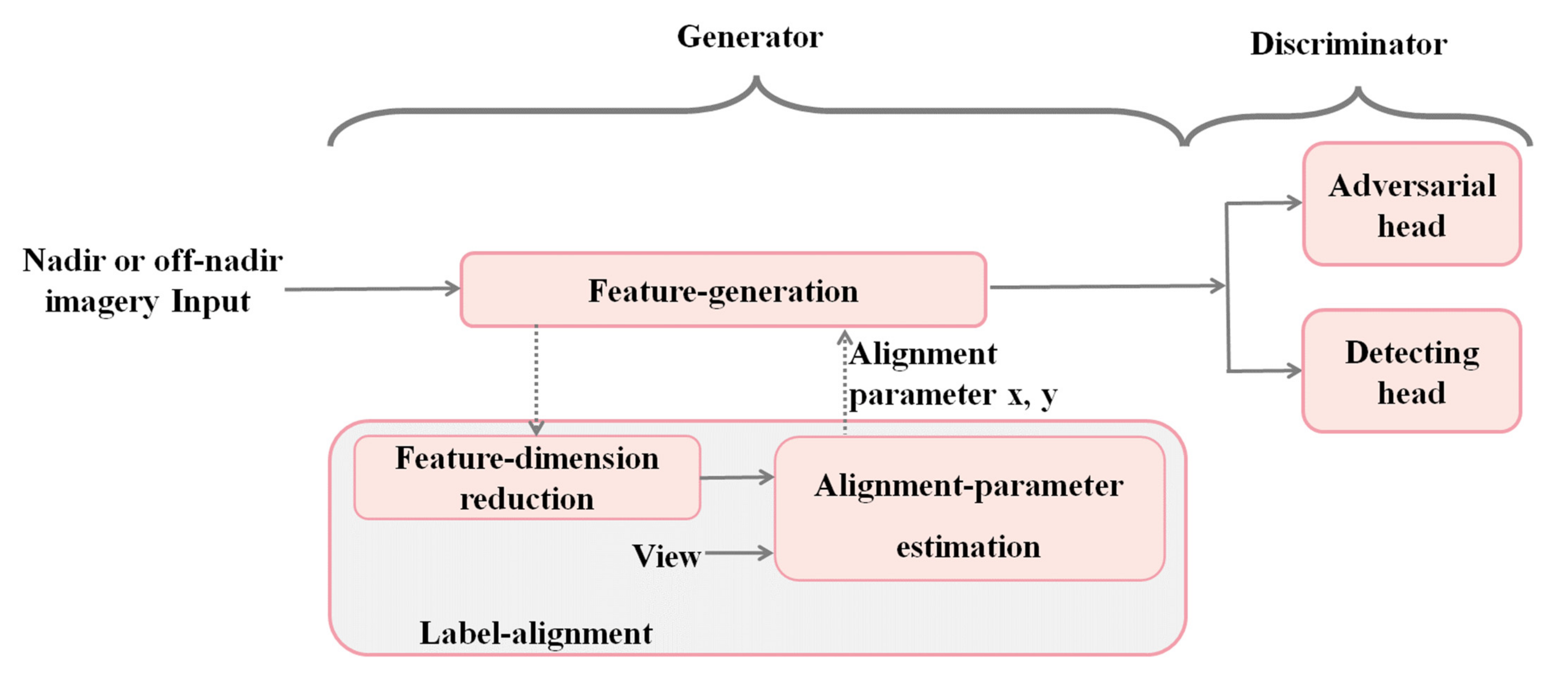
The generator consists of the feature generation and the label alignment. The feature-generation aims to generate the nadir-like representation for the off-nadir object. The label alignment aims to assist the feature generation, which aligns the feature map of the off-nadir object and aims to pertinently generate a nadir-like representation.
(3)
The discriminator consists of the adversarial head and the detecting head. The former aims to distinguish the nadir object and the off-nadir object, and the latter aims to accomplish the object detection task. Specifically, the discriminator is the multi-task collaborative learning between feature discrimination and object detection, rather than the single discrimination between the real nadir object and the generated one.
To the best of the authors knowledge, the NaGAN proposed in this paper is the first to apply the generative adversarial network to solve the challenge of multi-view object detection in the remote sensing domain.

2. Related Work

In the literature, image matching is widely used for viewpoint-invariant object detection [3], and viewpoint-invariant object detection methods usually concentrate on the following three aspects: feature description, feature matching, and feature learning.

2.1. Viewpoint-Invariant Object Detection by Image Matching

2.1.1. Feature Descriptor

A good feature descriptor is characterized by not only the invariance but also the distinguishability. Among various feature descriptors, the most widely used descriptors are SIFT (Scale-Invariant Feature Transform) [4], its variants, e.g., ASIFT [5], and SURF (Sped-Up Robust Features) [6]. SIFT is a landmark work in the research field of feature description and feature matching. SIFT and the more efficient SURF are powerful in terms of scale and rotation; however, they are limited in view-angle variance. ASIFT is adapted to viewpoint variation by simulating projections of different viewpoints.

2.1.2. Feature Matching

The shape features or geometrical structure of images are usually used for feature matching. In [7], the proposal was made to denote the structural attributes of images by a new feature descriptor, named the histogram of orientated phase congruency, and then the normalized cross-correlation was utilized for the similarity metric for template matching. In [8], a shape descriptor for image matching based on normalized cross-correlation and dense local self-similarity was presented. In [9], the shape context feature and SIFT feature were taken into account for remote sensing image matching. In [10], the position of the robot can be estimated by triangulating and matching the local submap of the autonomous robot using the method of maximizing the triangle similarity.
Deformable matching is an effective strategy for multi-view matching. For instance, the best-buddies-similarity (BBS) measure was proposed in [11] to improve matching performances impacted by occlusions, large deformation, and viewpoint variation. BBS relies only on a subset of points in the template, and it is more robust than previous methods. To reduce the drastic differences caused by viewpoint variation, [12] employed digital elevation models to acquire features for fast visual database inquiry. To seek the nearest neighbors for each query object, [13] developed an effective multiple nearest-neighbors matching method based upon dominant sets. The study of [14] was inspired by the classical thought of image registration to match images for different views. However, it stopped at matching without further object detection.

2.1.3. Feature Learning

The deep learning method can be applied for image matching and patch matching. In [15], a stacked auto-encoder was proposed to obtain unsupervised features for medical image registration. In [16], a Siamese network was presented in order to match image patches, which fetches patch-pair representations by coupled CNNs. In [17], the feature similarity between two image patches was measured by two of the same CNNs or two different CNNs. In [18], the traditional feature was substituted with the perspective-specific structural feature. In [19], a data augmentation method was proposed for multi-view image generation, making the detection model affine-invariant.
Unlike BBS, DDIS [20] employs the neural network and explicitly considers the deformation. Owing to its parameter-free merit, DDIS outperforms previous methods including BBS. OriCNN [21] enhances deep neural networks with the “commonsense” of orientation. Given a ground-level spherical panoramic image as a query input and a big georeferenced satellite image database, OriCNN utilizes a Siamese network to explicitly encode the orientation for each pixel.

2.2. Data Augmentation and Generation

Data augmentation generalizes the learning procedure of deep neural networks, and its goal is to improve the performance by augmenting the original dataset [22]. Currently, the mainstream data augmentation approach is on network-antagonistic augmentation. In [22], an approach named data augmentation optimized for GAN was proposed to enable the use of augmented data in GAN training to improve the learning capacity of the original distribution. The study of [23] was based on image conditional Generative Adversarial Networks to generate within-class data.
There are other ways to augment data besides GAN. In [24], data augmentation was applied for improving the federated learning approach. The proposed augmentation technique consists of image processing techniques, neural network architectures, and heuristic methods, and it improves the operation in federated learning by increasing the role of the server. In [25], data were augmented through image reconstruction to provide a better-quality image without any noise. The main idea was to find some important areas on an image by the heuristic algorithm and training network until a certain level of entropy within these areas was achieved.

3. The Proposed Approach

3.1. Overview of NaGAN

As shown in Figure 3, NaGAN comprises a generator and a discriminator. The generator aims to generate the nadir-like representation for the off-nadir object, and the discriminator aims to identify the quality of the generated features and detect objects on the nadir-like representations. Considering the difficulties in reducing the intra-class distance between off-nadir objects and nadir objects, the generator learns progressively and is adversarially constrained by the discriminator. With the iterated game, the detection accuracy for off-nadir objects is improved.

3.2. Modeling and Loss Function

3.2.1. Generator Modeling

The learning goal of the original GAN [26] is equivalent to a min-max two-player game, which is expressed as:
m i n G m a x D L D , G E x ~ p d a t a x log D x + E z ~ p z z log ( 1 D G z
where a generator G is trained to project data z from the noise distribution p z z to the distribution p d a t a x about data x , and a discriminator D estimates the probability of data originating from the distribution p d a t a x other than G . G aims to maximize the probability of D committing an error. E represents the mathematical expectation, and the objective function of GAN is defined as L D , G . In this paper, x and z are the representatives for nadir objects R n and off-nadir objects R o correspondingly. The generator function G is expected to convert the representations of the off-nadir object R o to the nadir-like one G R o , which is similar to the real one of the nadir object R n .
m i n G m a x D L D , G E R n ~ p d a t a R n log D R n + E R o ~ p R o z log ( 1 D G R o
For NaGAN, the generator consists of the feature generation and the label alignment. The former is used to generate the nadir-like representation for the off-nadir object with a convolutional network, and the latter aims to assist the former to generate more accurate nadir-like features.
(1) Feature generation
The generator network G Ψ g is trained with parameters Ψ g , i.e.,
Ψ g = arg m i n Ψ g L d i s G Ψ g R o
The loss function L d i s is the combination of the adversarial loss L d i s a d v and detection loss L d i s d t e produced by the discriminator, where L d i s is defined by formula (5), which provides feedback to the generator for further improving the feature generation performance.
(2) Label alignment
As the label used by the off-nadir object is the label of the nadir object, it is difficult to directly learn the representation G Ψ g R o for off-nadir objects to match the distribution of nadir object feature R n . For this reason, a new conditional-probability generator model called label alignment is introduced, which is conditioned on the additional supplementary semantic information, i.e., the view v and the high-level feature of the off-nadir object r , by which the generator is trained to learn features of the off-nadir object aligned to the nadir object via label alignment.
min G max D L ( D , G ) E R n ~ p d a t a ( R n ) log D ( R n ) + E R o ~ p R o ( z ) [ log ( 1 D ( G ( R o v , r a l i g n e d   f e a t u r e ) ) ]
By this way, the generator training is effective in learning the nadir-like representations for off-nadir objects. As a special case, if the input representation comes from the nadir object R n , the generator must only learn an equal mapping G Ψ g ( R n ) = R n .
The feature generation and label alignment have no loss functions. The training performance of the generator is determined by the adversarial head and the detecting head in the discriminator, then the losses of the two heads are used for gradient backpropagation. When the loss of the adversarial and detecting head is high enough for stopping the training procedure, it means that the generator does not generate a better nadir representation for the off-nadir object.

3.2.2. Modeling and Loss Function of Discriminator

As shown in Figure 4, to "supervise" the generator, the discriminator learns to not only distinguish the nadir-like representation of the off-nadir object and the real one of nadir object, but also to improve the detection performance by benefiting from the nadir-like features. The final loss function L d i s of the discriminator is defined as
L d i s = L d i s a d v + L d i s d t e
where L d i s a d v is the adversarial loss produced by the adversarial head, and L d i s d t e is the detecting loss by the detecting head.
(1) Adversarial head
The adversarial head aims to discriminate the nadir-like representation for the off-nadir object G Ψ g R o from the feature of the nadir object R n . The adversarial head D Ψ d i s a d v of the discriminator with the Ψ d i s a d v is obtained by the following optimization problem.
Ψ d i s a d v = arg min Ψ d i s a d v L d i s a d v ( G Ψ d i s a d v ( R o ) , R n )
Taking the real representation R n from each nadir object or the generated representation G Ψ g ( R o ) from each off-nadir object as the input, L d i s a d v is defined as
L d i s a d v = log D Ψ d i s a d v ( R n ) log ( 1 D Ψ d i s a d v ( G Ψ g ( R o ) ) )
(2) Detection head
To enhance the detecting accuracy by taking advantage of the generated nadir-like representation, the detecting head should be synchronously trained. The detecting head, D Ψ d i s d t e , parameterized by Ψ d i s d t e is obtained by optimizing the detection loss function L d i s d t e , i.e.,
Ψ d i s d t e = arg m i n Ψ d i s d t e L d i s d t e R n , R o
where L d i s d t e is the sum loss for bounding-box regression and classification.
Taking the nadir-like representation from each proposal as the input, the detecting head produces the class-level confidences p and the bounding-box regression offsets t u for each class, where the ground truth is the category u and the location v . L d i s d t e aims to improve the detecting accuracy for each object proposal with the help of the generated nadir-like representation:
L d i s d t e = L c l s p , u + 1 u 1 L r e g t u , v
where L c l s p , u = log p u is the log loss of ground truth class u for the classification, and L r e g is the smooth L 1 loss proposed in [27] for the bounding-box regression. The function u 1 is equal to 1 when u 1 , and 0 otherwise.

3.3. Network Architecture and Loss Design

Generator architecture. The purpose of the generator is to generate nadir-like representations for off-nadir objects. Thus, the generator augments the representations of nadir objects to nadir-like ones by feature-generation, and introduces more aligned details absent from the off-nadir object by label alignment. Before entering the generator, the ground truth of the off-nadir object shown by the green dotted bounding box in Figure 4 shares the same ground truth as the nadir object shown by the red dotted bounding box. After feature generation and label alignment, the generator generates the label alignment and nadir-like representation for the off-nadir object shown in the red dotted bounding box, and it continues to feed the generated nadir-like feature of the nadir object shown in the green dotted bounding box into the subsequent adversarial network.
The feature generation consists of the ResNet-50 [28] backbone network, FPN [29], and RPN [30]. The outputs of FPN are conv0~4. It can be informed from Figure 4 that the generator selects the conv4 feature as the input, which is extracted from the lower-level features layer by layer and includes the lower-level information.
The resulting features are then sent to the feature-dimension reduction, which consists of two FC layers F d 1 , F d 2 to decrease the dimension of the high-dimensional conv4 features, so the one-dimensional view information will not be submerged in the high-dimensional conv4 features. The following alignment-parameter estimation contains two FC layers F p 1 , F p 2 , aiming to regress two label-alignment parameters x, y along the horizontal and vertical direction, respectively. The feature generated is aligned according to the two parameters so that the label of the nadir object covers the off-nadir object, which assists the feature generation to pertinently generate a nadir-like representation for the off-nadir object. The output unit number of the four FC layers F d 1 , F d 2 , F p 1 , F p 2 are 512, 2, 3, and 2, respectively.
Discriminator architecture. The detection head follows the architecture of [28], which is comprised of two FC layers F d e t 1 , F d e t 2 and two sibling output layers F d e t 3 , F d e t 4 . The output unit numbers of 6 FC layers are 512, 512, 2048, 2048, 1, and 4, which represents 512, 1, and 4 dimensions embedding for adversarial, classification, and bounding-box regression tasks, respectively. To balance speed and performance, in the adversarial head, two fully connected layers F a d v 1 , F a d v 2 followed by sigmoid activation A s i g are used to learn the projection space from off-nadir object to nadir object.

4. Experiments

4.1. Experiments Setting

In the literature, there is little research on multi-view object detection of remote sensing imagery, and only one public dataset is available, SpaceNet [31]. To better reflect the visual heterogeneity of real-world imagery, the SpaceNet dataset includes various look directions and angles. In [31], Faster R-CNN [30] was analyzed. This method is different from NaGAN as it does not consider the discrimination between different perspectives.
The experiments were conducted on SpaceNet, which contains 27,486 overhead images over Atlanta, Georgia, USA on 22 December 2009. These images cover a 665 km2 geographic extent during 5 min. With 27 distinct looks from a wide range of viewing angles (−32.5° to 54.0°), the dataset was made during a single pass of the WorldView-2 satellite. The dataset covers different geographic locations, including industrial areas, suburbs, densely treed rural areas, and intensive urban regions. The view angle difference causes variations with respect to building appearance, size, and density [31]. Meanwhile, the dataset is disturbed by other complicating factors, e.g., changes in land-use, cloud cover, sun angle, or time-sensitive variables (such as seasonality), which enables careful assessment of the impact of the view on detection performance. The whole dataset was tiled into 900 pixels × 900 pixels tiles, and they were resampled to imitate a uniform resolution of 0.5 m/pixel.
The label of the most nadir imagery (−7.8°) was shared across all views. For structures occluded by trees, only the visible part was labeled. The average precision and average recall at IoU thresholds 0.5 and the averaged ones from 0.5 to 0.95 in steps of 0.05, i.e., [email protected], [email protected]:0.95 and [email protected], [email protected]:0.95, were used for measuring performance. [email protected] is also called the mean Average Precision (mAP).
The training, validation, and test set were split in 60/20/20 by randomly selecting geographic positions, and each split contained all views of the same scene. Each view was grouped into one of two classes: nadir (NADIR), | θ | 25 ° ; off-nadir (OFF), | θ | 25 ° . The image numbers corresponding to the above two groups were 11198 and 16288, correspondingly. This setting helped us evaluate a detector in different views. In all experiments, baselines were trained using all views (ALL), or OFF, or NADIR. In Figure 1, 27 views (-32.5° to 54.0°) on the test set were assessed separately.

4.2. Implementation Details

The implementation was based on 6 NVIDIA GeForce RTX 2080 Ti GPUs with 12GB memory. For a fair comparison, all ablation experiments were conducted within the MMDetection [32] toolbox built on the Pytorch platform with default parameters.
Hyperparameters. NaGAN was trained by stochastic gradient descent (abbreviated as SGD) with a momentum of 0.9, learning rate of 0.0025, and weight decay of 0.0002. When the discriminator was trained, each SGD batch contained 128 foreground candidate proposals. The RPN presented in [30] was used to produce object proposals.
Initialization and pretraining. The pretrained ResNet-50 model in [28] was used for initialization. For the generator and the discriminator, the parameters of additional FC layers and convolutional layers were initialized with "Xavier" [33]. Following [28], downsampling was performed straightly by convolutional layers with a stride of 2.
Activation strategy of label alignment at the testing stage. At the training stage, to align the object of the off-nadir imagery to the ground-truth bounding box of the nadir object, the label alignment was activated. At the testing stage, for observing mAP, the label alignment was still activated as the mAP measurement standard is also based on the ground truth of the nadir bounding box. For this reason, the label alignment was activated in Table 1, Table 2, Table 3, Table 4 and Table 5. In Figure 5, Figure 6, Figure 7 and Figure 8, to visualize the regression ability of the off-nadir object with NaGAN, the label alignment was inactivated.

4.3. Performance Analysis

Performances by different methods are listed in Table 1. For all methods, it can be observed from other views that [email protected] decreases gradually with the view from nadir −7.8° to other views. The reason is that the deformation of the off-nadir object increases the detection difficulty. The [email protected] descends to the lowest value at −32.5° and 54° views.
It can be observed from Table 1 that the proposed NaGAN outperforms other state-of-the-art methods on different views. Specifically, the presented approach NaGAN makes an obvious improvement, i.e., 1.4% on ALL subset and 1.6% on OFF subset over the sub-optimal performance, which demonstrates its superiority in detecting multi-view objects and off-nadir views. However, each of the other approaches makes a specific improvement on a particular bottleneck: Cascade increases the IOU threshold and improves the false positive sample quality stage by stage for better regression proposal; Retinanet and Libra focus on the sample, feature, or objective level imbalance to improve detection; Nas-fpn uses the neural architecture search method to find the best possible detection method; Htc improves detection performance by increasing the interaction between instance segmentation and detection. They treat the nadir and off-nadir objects equally as the same kind of object, so the intra-class differences result in a weaker performance than NaGAN. Fovea and Centripetal, respectively, improve over RetinaNet and CornerNet. However, they are inferior to NaGAN.
Table 1. Performance comparison for each view on SpaceNet in terms of [email protected] in %.
Model\View−32.5°−29.1°−25.4°−21.3°−16.9°−13.9°−10.5°−7.8°8.3°10.6°
Faster_r50 [30]52.155.658.562.363.465.766.167.367.367.2
Faster_r101 [30]41.449.654.859.361.163.865.266.666.566.3
Cascade_r50 [34]24.533.941.746.747.852.954.259.760.759.7
Cascade_r101 [34]26.035.646.852.656.059.159.861.760.063.0
Cascade_x101 [34]40.247.954.257.660.561.863.264.364.463.3
CornerNet [35]7.318.826.126.829.631.332.333.132.832.8
Fovea_r50 [36]19.638.144.750.153.058.059.561.261.861.1
Fovea_r101 [36]19.642.847.952.554.158.060.160.861.861.5
RetinaNet [37]37.846.751.355.858.160.962.463.464.463.4
Htc [38]32.644.951.156.359.463.264.565.865.965.6
Libra rcnn [39]25.935.647.955.760.362.363.865.065.965.3
Nas_fpn [40]13.329.547.953.157.258.860.361.361.761.2
Centripetal [41]5.520.747.455.358.563.364.766.166.267.0
NaGAN54.057.259.863.064.166.166.267.367.467.3
Model\View14.8°19.3°23.5°27.4°31.0°34.0°37.0°39.6°42.0°44.2°
Faster_r5066.965.564.462.059.057.756.051.849.139.8
Faster_r10166.364.763.561.157.954.650.844.643.534.1
Cascade_r5059.658.252.454.544.039.452.533.527.018.5
Cascade_r10157.856.657.853.151.250.353.635.134.328.3
Cascade_x10164.263.052.459.255.555.552.748.445.334.4
CornerNet32.831.931.731.029.728.125.621.421.619.8
Fovea_r5061.059.357.955.350.949.848.243.640.530.1
Fovea_r10161.959.659.457.353.651.448.944.043.434.3
RetinaNet_r5063.662.061.058.555.353.951.547.146.134.4
Htc65.864.262.960.355.655.552.848.345.635.1
Libra rcnn64.263.360.858.553.648.842.131.928.920.4
Nas_fpn61.460.859.657.254.353.550.847.044.931.3
Centripetal65.863.362.559.856.855.852.544.344.341.6
NaGAN67.265.864.862.559.658.456.752.650.040.8
Model\View46.1°47.8°49.3°50.9°52.2°53.4°54.0°ALLNADIROFF
Faster_r5036.940.937.226.926.711.47.552.764.743.7
Faster_r10127.533.228.420.619.87.02.148.063.635.4
Cascade_r5013.515.812.29.410.02.65.729.951.426.1
Cascade_r10115.015.819.510.68.53.36.931.359.120.9
Cascade_x10127.133.730.323.823.012.76.448.861.738.4
CornerNet17.517.815.69.610.73.41.023.431.017.8
Fovea_r5021.427.425.720.417.58.22.143.057.132.0
Fovea_r10126.732.929.620.421.311.44.345.258.035.5
RetinaNet_r5026.835.231.922.922.912.56.147.860.737.8
Htc26.532.029.122.320.511.23.548.262.136.9
Libra rcnn15.917.416.313.19.52.20.839.061.723.2
Nas_fpn21.932.431.118.917.53.41.143.058.631.4
Centripetal34.032.028.718.219.24.41.245.562.132.8
NaGAN38.142.338.728.528.413.29.454.165.145.3
Detailed comparisons of recall rate and precision rate curves in terms of [email protected]:0.95 and [email protected] are shown in Figure 5, which illustrates the performances of different approaches for each view. Note that the performances of negative (south-facing) views are poorer than those of positive (north-facing) angles. The underlying reason is the heterogeneity caused by the flight direction, lighting condition, and shadows. The proposed NaGAN exceeds all the existing methods and reaches the highest recall rate, which validates its superiority in detecting off-nadir objects. More importantly, performances of the off-nadir object and nadir object detection are improved at the same time, which demonstrates that NaGAN works for every view. In addition, as can be seen from Figure 5, the “Precision” performance decrease from the nadir to off-nadir view of NaGAN is slowest, which illustrates that NaGAN mitigates the negative impact of the off-nadir view on precision.
To better understand the novelty of the proposed approach, feature maps by Faster R-CNN and NaGAN are shown in Figure 6. In Figure 6, the above and below rows are, respectively, the bounding boxes and feature maps of Faster R-CNN and NaGAN in nadir and off-nadir images. By comparing the second row with the first row of the third column, it is easy to find that Faster R-CNN missed the off-nadir object on the left. As shown in the second and fourth column of the first row in Figure 6, as the off-nadir view and the nadir view on the left side of the house are quite different, only the right side of the house with the stronger feature is detected by Faster R-CNN. However, as can be seen from either the nadir or off-nadir view, the attention of NaGAN in the object area is significantly greater than that of Faster R-CNN, indicating that NaGAN has learned more discriminative features for the object. In addition, by comparing the second row with the first row, two feature maps from different views under NaGAN are more similar than that of Faster R-CNN. That is because NaGAN tends to generate nadir-like features for off-nadir objects.

4.4. The Effectiveness of the Label Alignment

In order to observe the changing trend of the label-alignment parameters with the satellite flight direction, the view from −32.5° to 54° is coded as 1~27. The view of 7° nadir is encoded as “8”, and its label-alignment parameter is set to 0 in each direction, which means the network does not adjust the feature map under this view. Figure 7 records label-alignment parameters of 5778 images (214 × 27 views) in the test dataset. The vertical axis is numbered for the view. The blue and red parts of the vertical axis are the label-alignment parameters, which correspond to the horizontal and vertical offset of the feature map. The offset ranges from −1.0 to 1.0, which means the offset is relative to the original feature map. The positive values in horizontal and vertical directions mean that the feature map is adjusted to the left and above, respectively, and vice versa. It can be inferred that the trend of vertical offsets from nadir to off-nadir along the flight direction is increasing, which demonstrates the effectiveness of label alignment.
“NaGAN for mAP” and “NaGAN” in two scenes are shown in Figure 8, where the views are −32.5°, −7.8°, and 54.0°. “NaGAN for mAP” and “NaGAN” denote the label alignment being active and inactive at the testing stage, respectively. Compared to Faster R-CNN, the bounding box in red by “NaGAN for mAP” is closer to “Ground Truth” in yellow, so the mAP of “NaGAN for mAP” is higher. “NaGAN” and “NaGAN for mAP” are the same training model, but the latter introduces inactive label alignment at the testing stage for better visualization. From Figure 8, NaGAN is better in classifying and localizing objects, which further justifies the proposed method. Feature maps of Faster R-CNN and NaGAN are shown below in the last two lines of Figure 8 for further comparison. Compared to Faster R-CNN, feature maps of NaGAN for nadir views −32.5 ° and −54.0° are more similar to the feature map for off-nadir view −7.8°, which shows that NaGAN has a better ability to learn nadir-like features for the off-nadir object than Faster R-CNN.

4.5. Comparison to Image Matching Method

In addition to the classical object detection methods in Section 4.3, some multi-view matching methods were used for comparison: template matching method DDIS and SIFT descriptor, and ASIFT descriptor. The template marked in green in Figure 9a is detected in the target imagery (Figure 9b) of 52° off-nadir using DDIS. In the corresponding matching likelihood maps (Figure 9c), the higher the peak position of the response, the more likely it is identified as the template. The green bounding box in Figure 9b is the matching ground truth, and the red is the matching result of DDIS. It can be seen that NaGAN in Figure 9 has a higher accuracy than DDIS. However, DDIS incorrectly located the object in the red bounding box. In fact, due to the limited adaptability to the variation in view, scale, and rotation, the template matching method is less reliable.
Moreover, due to the heterogeneity of multi-view remote sensing imagery, the variants of SIFT designed for general images are not effective. It is indicated from the result of SIFT and ASIFT [42] shown in Figure 10a and b that the 52° off-nadir imagery and −7.8° nadir imagery match 0 points by SIFT. The SIFT matching result shows that the off-nadir imagery cannot be matched with the referenced nadir imagery by the SIFT feature descriptor. ASIFT performs better with 119 matching points compared with SIFT. However, there are no matched points within the circular object, which is due to the large deformation within the target area, revealing that SIFT and ASIFT become unreliable for multi-view object detection. In conclusion, the matching methods in Section 2.1 are not good enough for multi-view object detection.

4.6. Ablation Studies

4.6.1. The Variant of Label Alignment

To demonstrate the necessity of the label alignment, the performance of NaGAN without label alignment is reported in Table 2. ”NaGAN w/o LAM” indicates the features generation without label alignment. Two additional experiments were implemented on the variant of label alignment. “NaGAN w/o IV” indicates the model of aligning the label for the off-nadir object without introducing the view. Another ablation experiment on the variant of label alignment about the feature-dimension reduction was implemented. “NaGAN w/o DD” means that the high-dimensional output features of FPN are directly sent to the alignment-parameter estimation without reducing the dimension by the feature-dimension reduction.
Table 2. Performance comparison about label alignment and its variant on SpaceNet. (R): [email protected], (P): [email protected]. (In %).
ModelOFF-NADIRALL
NaGAN w/o LAM(R)52.959.4
NaGAN w/o LAM(P)44.753.6
NaGAN w/o IV(R)53.059.7
NaGAN w/o IV(P)45.053.9
NaGAN w/o DD(R)52.959.7
NaGAN w/o DD(P)44.953.8
NaGAN(R)53.259.8
NaGAN(P)45.354.1
As can be seen from rows 1, 2 of Table 2, when using the label alignment, NaGAN obtains definite improvements in accuracy and recall over “NaGAN w/o LAM.” The recall and accuracy of NaGAN in off-nadir object detection are improved by 0.3% and 0.6%, respectively. In consequence, NaGAN enhances the generator by label alignment in compensating for the effect of the off-nadir view without the ground-truth label.
Comparing rows 3, 4 and 7, 8 in Table 2 shows that the label alignment without introducing the view, i.e., “NaGAN w/o IV,” can also regress the label-alignment parameters based on implicit information such as the shadow, illumination, and displacement of the building object, and make NaGAN perform better than other models. However, the introduction of the view in label alignment leads to a further performance promotion for NaGAN. Compared with not introducing the view, the recall and accuracy of NaGAN in off-nadir object detection increase by 0.2% and 0.3%, respectively. The reason is that the more the current view deviates from the nadir view, the greater the parameter of the label alignment needs to align with the ground truth. In this way, NaGAN helps the label alignment regress the label-alignment parameter.
From rows 5, 6 and 7, 8 in Table 2, the performance of “NaGAN w/o DD” is worse than that of NaGAN. Compared with not introducing feature-dimension reduction to label alignment, NaGAN improves the recall and accuracy of off-nadir object detection by 0.2% and 0.3%, respectively. The reason is that one-dimensional view information is submerged in the high-dimensional FPN features. Thus, NaGAN uses the feature-dimension reduction to make the dimension of the output features and the view introduced comparable in dimension, which is beneficial for the performance of NaGAN.

4.6.2. Different Layers of Feature Generation Utilized

The generator of NaGAN learns nadir-like representations of off-nadir objects from FPN higher-level layers. Especially, NaGAN selects the “Conv4” FPN layer of feature generation. In order to verify the optimization of this layer, three comparisons were conducted, employing features from Conv3 to Conv1 for learning the generator individually. It can be identified from Table 3 that the performance continuously declines by using features from other, higher layers. Compared with introducing Conv3 to Conv1 layers of FPN, the accuracy of off-nadir object detection is improved by 0.7%, 0.5%, and 0.2% with Conv4, respectively. In consequence, using high-level features from Conv4 shows the best performance.
Table 3. Performance comparisons on feature generation from different-level layers on SpaceNet. (R): [email protected], (P): [email protected] (in %).
ModelOFF-NADIRALL
NaGAN_Conv1(R)52.259.2
NaGAN_Conv1(P)44.653.7
NaGAN_Conv2(R)52.759.6
NaGAN_Conv2(P)44.853.8
NaGAN_Conv3(R)53.059.6
NaGAN_Conv3(P)45.154.0
NaGAN(R)53.259.8
NaGAN(P)45.354.1

4.6.3. Different Parameters for Label Alignment

The conversion used in the label alignment is a kind of affine transformation. The affine transformation needs to regress 6 parameters, and NaGAN needs to regress 2 parameters. In [43], the affine transformation was used for the classification task only. In the ablation experiment, the affine transform was applied to the object detection. It can be seen from Table 4 that the proposed label alignment method is superior to the affine transform method in which the accuracy and recall of off-nadir object detection are improved by 0.6% and 0.3%, respectively. “NaGAN_STN_6” and “NaGAN_LAM_2”, respectively, indicate in Table 4 that the alignment-parameter estimation predicts 6 parameters of STN, while the latter predicts two parameters.
Table 4. Performance comparison on NaGAN with STN or with the label alignment. (R): [email protected], (P): [email protected] (in %).
ModelOFF-NADIRALL
NaGAN_STN_6(R)52.659.5
NaGAN_STN_6(P)45.053.9
NaGAN_LAM_2(R)53.259.8
NaGAN_LAM_2(P)45.354.1

4.6.4. The Effectiveness of Adversarial Head

To verify the essentiality of the adversarial head, the performances of NaGAN with or without the adversarial head during training are reported in Table 5. “NaGAN_w/o AH” signifies NaGAN without the adversarial head optimization step. “NaGAN_AH” denotes adversarially training the original nadir feature and the nadir-like off-nadir representation. By comparing “NaGAN_with AH” with “NaGAN_w/o AH,” it can be observed that certain improvements can be gained with the adversarial head. Compared with not introducing the adversarial head, the recall and accuracy of off-nadir object detection in NaGAN are improved by 0.7% and 0.6%, respectively, which demonstrates that the adversarial head helps to enhance the performance of NaGAN.
Table 5. Performance comparison on adversarial head. (R): [email protected], (P): [email protected] (in %).
ModelOFF-NADIRALL
NaGAN_w/o AH(R)52.559.2
NaGAN_w/o AH(P)44.753.6
NaGAN_with AH(R)53.259.8
NaGAN_with AH(P)45.354.1

5. Conclusions

A novel generative adversarial network named NaGAN is proposed in this paper to solve the challenging issue of multi-view object detection. To enhance detection performance, NaGAN generates nadir-like representations for off-nadir objects by training the generator network and the discriminator network end-to-end. The generator aims to learn discriminative features from the label-aligned feature and to boost the nadir-like representations for off-nadir objects. Competition in the end-to-end optimization of both the generator and the discriminator promotes NaGAN to generate nadir-like representations for nadir objects for boosting detection performance. The experiments demonstrate the advantage of the proposed NaGAN in detecting off-nadir objects.
Generally, GAN generates an image that meets the human eye’s need for habits such as intelligibility and clarity. Compared to GAN, NaGAN aims to directly generate the view-invariant feature, i.e., nadir-like representation for off-nadir object, rather than images from different views. Thus, NaGAN is a specific model designed for off-nadir object detection under the guidance of the GAN methodology. In the future, it will be interesting to investigate whether GAN is capable of generating nadir view images from off-nadir view images. It will be very helpful in data augmentation.

Author Contributions

Conceptualization, Z.Z.; methodology, X.Z. and L.N.; software, L.N.; validation, X.Z.; formal analysis, X.Z., L.N. and C.H.; investigation, L.N., L.Z. and K.G.; writing—original draft preparation, L.N.; writing—review and editing, C.H., L.N. and X.Z.; visualization, L.N.; supervision, C.H.; project administration, P.W.; funding acquisition, C.H. and Z.Z. All authors have read and agreed to the published version of the manuscript.

Funding

This research was supported by National Natural Science Foundation of China under Grants 62071466 and Guangxi Natural Science Foundation under Grant No. 2018GXNSFBA281086.

Data Availability Statement

The data used in the manuscript are all public data. The data of SpaceNet were downloaded from the official website: https://spacenet.ai/off-nadir-building-detection/ (accessed on 25 November 2021).

Conflicts of Interest

The authors declare no conflict of interest.

References

  1. Ehsani, K.; Mottaghi, R.; Farhadi, A. Segan: Segmenting and generating the invisible. In Proceedings of the IEEE Conference on Computer Vision and Pattern Recognition, Salt Lake City, UT, USA, 18–23 June 2018; pp. 6144–6153. [Google Scholar]
  2. Liao, K.; Lin, C.; Zhao, Y.; Gabbouj, M. DR-GAN: Automatic Radial Distortion Rectification Using Conditional GAN in Real-Time. IEEE Trans. Circuits Syst. Video Technol. 2019, 30, 725–733. [Google Scholar] [CrossRef]
  3. Turner, D.; Lucieer, A.; Malenovský, Z.; King, D.H.; Robinson, S.A. Spatial Co-Registration of Ultra-High Resolution Visible, Multispectral and Thermal Images Acquired with a Micro-UAV over Antarctic Moss Beds. Remote Sens. 2014, 6, 4003–4024. [Google Scholar] [CrossRef] [Green Version]
  4. Ng, P.C.; Henikoff, S. SIFT: Predicting amino acid changes that affect protein function. Nucleic Acids Res. 2003, 31, 3812–3814. [Google Scholar] [CrossRef] [PubMed] [Green Version]
  5. Morel, J.-M.; Yu, G. ASIFT: A new framework for fully affine invariant image comparison. SIAM J. Imaging Sci. 2009, 2, 438–469. [Google Scholar] [CrossRef]
  6. Bay, H.; Tuytelaars, T.; Van Gool, L. Surf: Speeded up robust features. In Proceedings of the European Conference on Computer Vision, Graz, Austria, 7–13 May 2006; pp. 404–417. [Google Scholar]
  7. Ye, Y.; Shan, J.; Bruzzone, L.; Shen, L. Robust Registration of Multimodal Remote Sensing Images Based on Structural Similarity. IEEE Trans. Geosci. Remote Sens. 2017, 55, 2941–2958. [Google Scholar] [CrossRef]
  8. Ye, Y.; Shen, L.; Hao, M.; Wang, J.; Xu, Z. Robust Optical-to-SAR Image Matching Based on Shape Properties. IEEE Geosci. Remote Sens. Lett. 2017, 14, 564–568. [Google Scholar] [CrossRef]
  9. Yang, K.; Pan, A.; Yang, Y.; Zhang, S.; Ong, S.H.; Tang, H. Remote Sensing Image Registration Using Multiple Image Features. Remote Sens. 2017, 9, 581. [Google Scholar] [CrossRef] [Green Version]
  10. Li, Q.; Nevalainen, P.; Queralta, J.; Heikkonen, J.; Westerlund, T. Localization in Unstructured Environments: Towards Autonomous Robots in Forests with Delaunay Triangulation. Remote Sens. 2020, 12, 1870. [Google Scholar] [CrossRef]
  11. Dekel, T.; Oron, S.; Rubinstein, M.; Avidan, S.; Freeman, W.T. Best-Buddies Similarity for robust template matching. In Proceedings of the Computer Vision and Pattern Recognition, Boston, MA, USA, 7–12 June 2015; pp. 2021–2029. [Google Scholar]
  12. Saurer, O.; Baatz, G.; Köser, K.; Ladický, L.; Pollefeys, M. Image Based Geo-localization in the Alps. Int. J. Comput. Vis. 2016, 116, 213–225. [Google Scholar] [CrossRef]
  13. Tian, Y.; Chen, C.; Shah, M. Cross-View Image Matching for Geo-Localization in Urban Environments. In Proceedings of the IEEE Conference on Computer Vision and Pattern Recognition, Honolulu, HI, USA, 21–26 July 2017; pp. 1998–2006. [Google Scholar] [CrossRef] [Green Version]
  14. Park, J.-H.; Nam, W.-J.; Lee, S.-W. A Two-Stream Symmetric Network with Bidirectional Ensemble for Aerial Image Matching. Remote Sens. 2020, 12, 465. [Google Scholar] [CrossRef] [Green Version]
  15. Wu, G.; Kim, M.; Wang, Q.; Munsell, B.C.; Shen, D. Scalable High-Performance Image Registration Framework by Unsupervised Deep Feature Representations Learning. IEEE Trans. Biomed. Eng. 2016, 63, 1505–1516. Erratum in IEEE Trans. Biomed. Eng. 2017, 64, 250. [Google Scholar] [CrossRef] [PubMed] [Green Version]
  16. Han, X.; Leung, T.; Jia, Y.; Sukthankar, R.; Berg, A.C. Matchnet: Unifying feature and metric learning for patch-based matching. In Proceedings of the IEEE Conference on Computer Vision and Pattern Recognition, Boston, MA, USA, 7–12 June 2015; pp. 3279–3286. [Google Scholar]
  17. Zagoruyko, S.; Komodakis, N. Learning to compare image patches via convolutional neural networks. In Proceedings of the IEEE Conference on Computer Vision and Pattern Recognition, Boston, MA, USA, 7–12 June 2015; pp. 4353–4361. [Google Scholar]
  18. Zhang, X.; Liu, Y.; Huo, C.; Xu, N.; Wang, L.; Pan, C. PSNet: Perspective-sensitive convolutional network for object detection. Neurocomputing 2022, 468, 384–395. [Google Scholar] [CrossRef]
  19. Zhang, X.; Huo, C.; Pan, C. View-Angle Invariant Object Monitoring Without Image Registration. In Proceedings of the ICASSP 2020-2020 IEEE International Conference on Acoustics, Speech and Signal Processing (ICASSP), Barcelona, Spain, 4–8 May 2020; pp. 2283–2287. [Google Scholar]
  20. Talmi, I.; Mechrez, R.; Zelnik-Manor, L. Template Matching with Deformable Diversity Similarity. In Proceedings of the Computer Vision and Pattern Recognition, Honolulu, HI, USA, 21–26 July 2017; pp. 1311–1319. [Google Scholar]
  21. Liu, L.; Li, H. Lending Orientation to Neural Networks for Cross-View Geo-Localization. In Proceedings of the IEEE/CVF Conference on Computer Vision and Pattern Recognition, Long Beach, CA, USA, 15–20 June 2019; pp. 5617–5626. [Google Scholar] [CrossRef] [Green Version]
  22. Tran, N.-T.; Tran, V.-H.; Nguyen, N.-B.; Nguyen, T.-K.; Cheung, N.-M. On Data Augmentation for GAN Training. IEEE Trans. Image Process. 2021, 30, 1882–1897. [Google Scholar] [CrossRef] [PubMed]
  23. Antoniou, A.; Storkey, A.; Edwards, H. Augmenting Image Classifiers Using Data Augmentation Generative Adversarial Networks. In Proceedings of the International Conference on Artificial Neural Networks, Bratislava, Slovakia, 15–18 September 2018; pp. 594–603. [Google Scholar] [CrossRef] [Green Version]
  24. Połap, D.; Woźniak, M. A hybridization of distributed policy and heuristic augmentation for improving federated learning approach. Neural Networks 2022, 146, 130–140. [Google Scholar] [CrossRef] [PubMed]
  25. Połap, D.; Srivastava, G. Neural image reconstruction using a heuristic validation mechanism. Neural Comput. Appl. 2020, 33, 10787–10797. [Google Scholar] [CrossRef]
  26. Goodfellow, I.; Pouget-Abadie, J.; Mirza, M.; Xu, B.; Warde-Farley, D.; Ozair, S.; Courville, A.; Bengio, Y. Generative Adversarial Nets. In Proceedings of the Advances in Neural Information Processing Systems27: Annual Conference on Neural Information Processing Systems 2014, Montreal, QC, Canada, 8–13 December 2014; pp. 2672–2680. [Google Scholar]
  27. Girshick, R. Fast R-CNN. In Proceedings of the International Conference on Computer Vision, Santiago, Chile, 7–13 December 2015; pp. 1440–1448. [Google Scholar]
  28. He, K.; Zhang, X.; Ren, S.; Sun, J. Deep Residual Learning for Image Recognition. In Proceedings of the Computer Vision and Pattern Recognition, Las Vegas, NV, USA, 27–30 June 2016; pp. 770–778. [Google Scholar]
  29. Lin, T.-Y.; Dollar, P.; Girshick, R.; He, K.; Hariharan, B.; Belongie, S. Feature Pyramid Networks for Object Detection. In Proceedings of the Computer Vision and Pattern Recognition, Honolulu, HI, USA, 21–26 June 2017; pp. 936–944. [Google Scholar]
  30. Ren, S.; He, K.; Girshick, R.; Sun, J. Faster R-CNN: Towards Real-Time Object Detection with Region Proposal Networks. IEEE Trans. Pattern Anal. Mach. Intell. 2017, 39, 1137–1149. [Google Scholar] [CrossRef] [PubMed] [Green Version]
  31. Weir, N.; Lindenbaum, D.; Bastidas, A.; Etten, A.; Kumar, V.; McPherson, S.; Shermeyer, J.; Tang, H. SpaceNet MVOI: A Multi-View Overhead Imagery Dataset. In Proceedings of the International Conference on Computer Vision, Seoul, Korea, 27–28 October 2019; pp. 992–1001. [Google Scholar]
  32. Chen, K.; Wang, J.; Pang, J.; Cao, Y.; Xiong, Y.; Li, X.; Sun, S.; Feng, W.; Liu, Z.; Xu, J.; et al. MMDetection: Open MMLab Detection Toolbox and Benchmark. arXiv 2019, arXiv:1906.07155. [Google Scholar]
  33. Glorot, X.; Bengio, Y. Understanding the difficulty of training deep feedforward neural networks. In Proceedings of the International Conference on Artificial Intelligence and Statistics, Sardinia, Italy, 13–15 May 2010; pp. 249–256. [Google Scholar]
  34. Cai, Z.; Vasconcelos, N. Cascade R-CNN: Delving into High Quality Object Detection. In Proceedings of the Computer Vision and Pattern Recognition, Salt Lake City, UT, USA, 18–23 June 2018; pp. 6154–6162. [Google Scholar]
  35. Law, H.; Deng, J. CornerNet: Detecting Objects as Paired Keypoints. Int. J. Comput. Vis. 2020, 128, 642–656. [Google Scholar] [CrossRef] [Green Version]
  36. Kong, T.; Sun, F.; Liu, H.; Jiang, Y.; Li, L.; Shi, J. FoveaBox: Beyound Anchor-Based Object Detection. IEEE Trans. Image Process. 2020, 29, 7389–7398. [Google Scholar] [CrossRef]
  37. Lin, T.-Y.; Goyal, P.; Girshick, R.; He, K.; Dollár, P. Focal Loss for Dense Object Detection. IEEE Trans. Pattern Anal. Mach. Intell. 2020, 42, 318–327. [Google Scholar] [CrossRef] [PubMed] [Green Version]
  38. Chen, K.; Ouyang, W.; Loy, C.C.; Lin, D.; Pang, J.; Wang, J.; Xiong, Y.; Li, X.; Sun, S.; Feng, W.; et al. Hybrid Task Cascade for Instance Segmentation. In Proceedings of the Computer Vision and Pattern Recognition, Long Beach, CA, USA, 16–20 June 2019; pp. 4974–4983. [Google Scholar]
  39. Pang, J.; Chen, K.; Shi, J.; Feng, H.; Ouyang, W.; Lin, D. Libra R-CNN: Towards Balanced Learning for Object Detection. In Proceedings of the Computer Vision and Pattern Recognition, Long Beach, CA, USA, 15–20June 2019; pp. 821–830. [Google Scholar]
  40. Ghiasi, G.; Lin, T.-Y.; Le, Q.V. NAS-FPN: Learning Scalable Feature Pyramid Architecture for Object Detection. In Proceedings of the IEEE/CVF Conference on Computer Vision and Pattern Recognition, Long Beach, CA, USA, 15–20 June 2019; pp. 7029–7038. [Google Scholar] [CrossRef] [Green Version]
  41. Dong, Z.; Li, G.; Liao, Y.; Wang, F.; Ren, P.; Qian, C. CentripetalNet: Pursuing High-Quality Keypoint Pairs for Object Detection. In Proceedings of the Ieee/Cvf Conference on Computer Vision and Pattern Recognition, Seattle, WA, USA, 13–19 June 2020; pp. 10516–10525. [Google Scholar] [CrossRef]
  42. ASIFT. Available online: http://www.cmap.polytechnique.fr/~yu/research/ASIFT/demo.html (accessed on 5 November 2021).
  43. Jaderberg, M.; Simonyan, K.; Zisserman, A.; Kavukcuoglu, K. Spatial transformer networks. In Proceedings of the Neural Information Processing Systems, Montreal, QC, Canada, 7–12 December 2015; pp. 2017–2025. [Google Scholar]
Figure 1. Difficulty illustration of object detection on off-nadir image. (a) The nadir object is different from the off-nadir object with respect to appearance due to viewpoint differences and imaging uncertainties, and features of nadir and off-nadir objects are exhibited differently by traditional detectors, which impacts detection performances. (b) NaGAN aims to generate the nadir-like representation for the off-nadir object, and a higher detection accuracy is gained on off-nadir images.
Remotesensing 14 00975 g001
Figure 2. Label inaccuracy on off-nadir images. The upper three images are taken at −32.5°, −7.8°, and 54°. There is no ground truth of the off-nadir object, and the direct utilization of the ground truth of the nadir view will impact the detection performance.
Remotesensing 14 00975 g002
Figure 3. Overview of NaGAN. NaGAN consists of a generator and a discriminator. The generator aims to generate a nadir-like representation for the off-nadir object, which consists of the feature generation and the label alignment. The former is used to generate the nadir-like representation for the off-nadir object, while the latter helps the former align the off-nadir object to the label of the nadir object. The discriminator consists of two heads, the adversarial head and the detecting head. The adversarial head aims to discriminate the generated nadir-like representation of the off-nadir object from the real nadir object, and the detecting head aims to benefit the detection accuracy.
Remotesensing 14 00975 g003
Figure 4. The network architecture of NaGAN. (a) The feature generation in the generator consists of the ResNet-50 backbone network, FPN, and RPN. The label alignment takes features learned from the FPN high-level layer conv4 as the input. Then, the features are sent to feature-dimension reduction to decrease the feature dimension. After that, the new low-dimensional features are then fed to alignment-parameter estimation to regress the label-alignment parameters. (b) The discriminator takes the features of the nadir object and the nadir-like representation of the off-nadir object as inputs. The adversarial head comprises two fully connected (FC) layers and sigmoid activation sequentially. The detection head is constituted by two FC layers and subsequently two output layers, and the latter are employed for bounding box regression and classification, respectively.
Remotesensing 14 00975 g004
Figure 5. Performance of [email protected]:0.95 and [email protected] of different methods for various views. Many prevailing models and NaGAN trained on ALL were assessed for the building detection task, and the [email protected]:0.95 and [email protected] results are shown for each evaluated view. Imagery facing south is symbolized with a negative number, whereas views facing North are presented with a positive value.
Remotesensing 14 00975 g005
Figure 6. Bounding boxes and feature maps of Faster R-CNN and NaGAN in nadir and off-nadir images.
Remotesensing 14 00975 g006
Figure 7. Records of the label-alignment parameters for 5778 images (214 × 27 views) from 214 scenes in the test dataset. It can be observed that the trend of vertical offsets from nadir to off-nadir along the flight direction of satellites is increasing, which demonstrates the effectiveness of label alignment.
Remotesensing 14 00975 g007
Figure 8. Comparison of detection results and feature maps of Faster R-CNN and NaGAN. The bounding box in red by Faster R-CNN is less accurate than NaGAN in green for views −32.5° and 52.5°. In addition, compared to Faster R-CNN, feature maps of NaGAN for nadir views −32.5 ° and −54.0 ° are more similar to the feature map for off-nadir view −7.8°, which shows that NaGAN has a better ability to learn nadir-like features for the off-nadir object than Faster R-CNN.
Remotesensing 14 00975 g008
Figure 9. The result of the DDIS matching method. (a) The template marked in green. (b) The detected target on 52° off-nadir image. (c) The corresponding matching likelihood map.
Remotesensing 14 00975 g009
Figure 10. Matching performance comparison. (a) SIFT. (b) ASIFT.
Remotesensing 14 00975 g010
Publisher’s Note: MDPI stays neutral with regard to jurisdictional claims in published maps and institutional affiliations.

