

Sensing and Deep CNN-Assisted Semi-Blind Detection for Multi-User Massive MIMO Communications

1
School of Software Engineering, Tongji University, Shanghai 201804, China
2
Engineering Research Center of Key Software Technologies for Smart City Perception and Planning, Ministry of Education, Shanghai 200003, China
3
School of Information and Electronics, Beijing Institute of Technology, Beijing 100081, China
4
Beijing Institute of Technology Chongqing Innovation Center, Chongqing 401120, China
5
School of Information and Communication Engineering, Beijing University of Posts and Telecommunications, Beijing 100876, China
6
School of Electronic and Information Engineering, Tongji University, Shanghai 201804, China
*
Author to whom correspondence should be addressed.
Remote Sens. 2024, 16(2), 247; https://0-doi-org.brum.beds.ac.uk/10.3390/rs16020247
Submission received: 14 December 2023
/
Revised: 1 January 2024
/
Accepted: 5 January 2024
/
Published: 8 January 2024
(This article belongs to the Special Issue Artificial Intelligence-Driven Methods for Remote Sensing Target and Object Detection II)
Abstract
:Attaining precise target detection and channel measurements are critical for guiding beamforming optimization and data demodulation in massive multiple-input multiple-output (MIMO) communication systems with hybrid structures, which requires large pilot overhead as well as substantial computational complexity. With benefits from the powerful detection characteristics of MIMO radar, we aim for designing a novel sensing-assisted semi-blind detection scheme in this paper, where both the inherent low-rankness of signal matrix and the essential knowledge about geometric environments are fully exploited under a designated cooperative manner. Specifically, to efficiently recover the channel factorizations via the formulated low-rank matrix completion problem, a low-complexity iterative algorithm stemming from the alternating steepest descent (ASD) method is adopted to obtain the solutions in case of unknown noise statistics. Moreover, we take one step forward by employing the denoising convolutional neural network (DnCNN) to preprocess the received signals due to its favorable performance of handling Gaussian denoising. The overall paradigm of our proposed scheme consists of three stages, namely (1) target parameter sensing, (2) communication signal denoising and (3) semi-blind detection refinement. Simulation results show that significant estimation gains can be achieved by the proposed scheme with reduced training overhead in a variety of system settings.
1. Introduction
With the vigorous development of the wireless communication industry and the deep integration with intelligent information processing technology, various remote sensing applications, e.g., vehicle-to-everything, smart manufacturing and environmental monitoring, come to the force, which puts forward increasing demand for network capacity and spectrum utilization [1,2,3]. As an important solution to support ultra-high transmission rate and intelligence requirements of the future mobile communications, massive multiple-input multiple-output (MIMO) inherently allows for simultaneous serving of multiple users by deploying large-scale antennas at a base station (BS) and facilitates the generation of directed beams towards target users, thereby expanding connected density and reducing the mutual interference in scenarios involving multiple users [4,5]. To obtain larger antenna gains and alleviate the pressure of spectrum scarcity, exploring novel transceiver design and frame structure operating at higher frequencies, such as the millimeter wave (mmWave) band [6,7], paves the way to guarantee reliable communications while enabling satisfactory user experiences.
1.1. Background
Considering that major obstacles preventing the deployment of massive MIMO are related to huge hardware costs and power consumptions imposed on the excessive number of radio frequency (RF) chains, hybrid analog/digital structures have been utilized to canonically route the RF chains via a well-designed phase-shifter network [8,9,10]. Furthermore, to compensate for prominent path loss encountered in mmWave channels and mitigate severe interference among multiple users, optimization on hybrid beamforming is expected to strike a favorable tradeoff between cost and rate [11,12,13]. One of the critical premises for obtaining the optimal beamforming is to acquire channel state information. Nevertheless, accurate channel estimation is challenging due to increased dimensionality of signal matrix and the application of hybrid architecture that limits the available observations. In this way, developing an efficient receiver scheme to enhance the transmission performance is essential in hybrid massive MIMO systems.
Recently, based on the fact that radar and communication systems share similar underline signal processing and gradually work in approximate frequency bands, there emerges a technological trend to integrate both functionalities into a single system [14,15,16], which offers an exciting opportunity to implement radar sensing by inherent wireless infrastructures. Given the potential ability of rapid and wide-range detection, it would be beneficial to leverage the radar sensing to fully extract geometric information from the surrounding environment [17,18] and thus assist in obtaining more precise parameter estimations. Toward this end, the coexistence of radar and communication components will constitute the primary architecture of this paper for enhanced performance gains.
1.2. Problem Being Addressed
Against the above background, as the dimensionality of antennas and carrier frequencies proliferate, the task of effectively balancing detection performance with computational cost becomes increasingly arduous. Consequently, the critical problem to be addressed is to propose novel solutions for comprehensive extraction of valuable information from the received signals in hybrid massive MIMO communication systems, thereby contributing to more reliable and cost-effective channel estimators.
1.3. Existing Solutions
In the literature, various channel estimators have been conducted for guiding the follow-up decoding and beamforming operations in hybrid massive MIMO systems. Among them, many techniques refer to the non-blind detections, which perform explicit channel estimation basically by transmitting and dealing with pilot symbols [19,20,21]. However, as the number of antennas increases, the pilot overhead could be enlarged accordingly and makes a negative impact on spectral efficiency. To address such issue, several research works began to focus on leveraging the sparse representation exhibited in delay-domain or angle-domain of mmWave channels [22,23,24], based on which a number of compressed-sensing (CS) tools have been adopted to figure out the formulated sparse recovery problem. Considering the grid-based CS estimator may lead to effects of basis mismatch, another gridless method appeared to construct continuous parameter domain by employing the atomic norm minimization [25]. Moreover, in order to avoid substantial computational complexity caused by high-dimensional optimizations and exploit more information from the payload data, our prior work [26] has proposed a semi-blind detection scheme for a hybrid massive MIMO system over frequency-selective fading channels, which utilized the uplink data as virtual pilots to improve the accuracy of channel estimation and data detection. However, the existing research has not sufficiently capitalized on the intrinsic features of massive MIMO systems and realistic channel characteristics, which constitute a significant challenge for achieving better tradeoff between training overhead and detection performance.
In addition to searching for rich scattering assumptions at higher frequencies, the low-rankness of massive MIMO systems has also been widely considered. In [27], according to the fact that both the number of BS antennas and the number of symbols in one coherence block are typically larger than the number of active users, the joint channel and data estimation was modeled as a low-rank matrix completion problem, for which two iterative algorithms were put forward to effectively recover the original channel and data. Moreover, schemes exploiting both the low-rank property and the knowledge of array responses have been proposed in [28,29,30], where the initial channel estimates provided by solutions to an inductive matrix completion would be further refined through multiple stages. Without loss of generality, most of the existing methods need to recover the matrix factorizations following an alternating minimization procedure [31,32,33]. Adhering to the existing methodologies, the intricate matrix multiplication or matrix inversion would induce unacceptable computational costs, especially when generalized to large-scale problems. As an effort to relieve the computational burden, an alternating steepest descent (ASD) algorithm was introduced in [34] to replace the least squares (LS) subproblem solutions with exact line-search updates. In view of the simplicity and moderate accuracy in the presence of non-negligible noise, we are inspired to tailor the ASD algorithm for estimating channels in hybrid massive MIMO systems.
Instead of simply obeying stochastic distributions, more realistic channels consisting of multiple propagation paths usually display a certain geometric structure. Since the process of communication channel estimation is similar to the radar target detection to some extent, research on making full use of sensing parameters to support communication functionality has attracted growing attention [35,36,37]. For example, by combining both functionalities of phased-MIMO radar and hybrid communication in the mmWave band, a novel strategy for joint target detection and channel estimation was proposed in [35]. To reduce the spectral resources as well as hardware cost, the employment of radar sensing for assisting the prediction of motion parameters in vehicular communication networks was investigated in [36]. Moreover, a robust MIMO-radar-aided channel estimation scheme deployed in multi-user (MU) MIMO communication systems has proven to be advantageous in improving the estimation accuracy with fewer training overhead [37]. Given that channel estimation may suffer from severe performance degradation in low signal-to-noise ratio (SNR) regions due to conceivable noise enhancement along with the LS-based estimation process, a supervised deep-learning (DL)-based signal denoiser was also involved in [37] to eliminate the noise on received signals before estimating the channel gains. However, training a neural network with high-dimensional signals and large datasets seems not tolerable in terms of complexity and latency [38]. Therefore, developing a cost-effective signal denoising module to make the state-of-the-art intelligent algorithms practically implementable for massive MIMO channel estimation is worth exploring.
1.4. Motivations and Objectives
A summary of the existing literature is provided in Table 1. The motivation for this paper stems from the notable limitations in current receiver techniques for hybrid massive MIMO communication systems. As one can see, challenges of large pilot overhead and substantial computational complexity will arise due to increased dimensionality and complicated signal nature in hybrid architectures, which restrict observation capabilities. Additionally, the growing demand for employing radar sensing in extracting environment information motivates us to seek advisable coordination between sensing and communication modules. In light of these challenges, the objective of this paper is to develop an efficient detection scheme tailored for hybrid massive MIMO systems with the aid of radar sensing, aimed at enhancing estimation performance and alleviating computational burdens.
1.5. Our Proposal and Contributions
In this paper, we propose a sensing and deep CNN-assisted semi-blind detection refinement scheme for a hybrid massive MU-MIMO system, where different functional modules, i.e., radar and communication, are integrated into the BS by partitioning multiple antennas. Specifically, both the low-rankness and geometric characteristic of high-frequency channels are fully exploited in a progressive manner. To reduce the large training overhead and substantial computational complexity, a novel transmission frame and an efficient receiver scheme are presented that can be split into three stages, namely (1) target parameter sensing, (2) communication signal denoising and (3) semi-blind detection refinement. Below, we crisply summarize the main contributions in this paper:
- A novel time-division duplex (TDD) transmission frame capable of coordinating the radar and communication operations is designed, based on which the root multiple signal classification (MUSIC) algorithm is firstly applied to environment sensing and then the extracted target angle information is utilized for refining the subsequent communication detection results.
- A generic representation for analog combining with phase shifters is considered, and the signal recovery problem is transformed into a low-rank matrix completion. To obtain the matrix factorizations with lower complexity, an iterative algorithm modified from ASD is proposed without any prior knowledge of noise statistics. In addition, different from the conventional pilot-only method, the semi-blind detection scheme is employed with reduced training overhead.
- A pre-trained denoising convolutional neural network (DnCNN) is adopted to preprocess the received signals before performing the semi-blind detection, which attempts to handle Gaussian noise removal with unknown noise level and shows powerful ability of improved accuracy especially in low SNR regions.
The remainder of this paper is organized as follows. In Section 2, the system model is presented and the conventional pilot-only estimation method is reviewed. By transforming the signal recovery problem into a low-rank matrix completion, our proposed sensing and deep CNN-assisted semi-blind detection scheme is detailed with three stages in Section 3. Simulation results are provided in Section 4. Finally, conclusions are given in Section 5.
Notations: The list of acronyms used in this paper is summarized in Table 2. Unless otherwise specified, bold uppercase letters are used to represent matrices, bold lowercase letters are used to represent vectors and scalars are denoted by normal font. and denote the i-th row and j-th column of , respectively. denotes the -th entry of . , and denote the operations of transpose, Hermitian transpose and element-wise conjugate, respectively. stands for a diagonal matrix with diagonal elements given by the vector . and represent the expectation operation and vectorization operation, respectively.
2. System Model and Background
In this paper, we consider a sensing-assisted hybrid massive MU-MIMO communication system, as shown in Figure 1, where K single-antenna users are served by a BS with two modules: one for the uplink communication and the other for the target sensing. Similarly as introduced in [37], the system operates in TDD mode and the multi-functional transmission frame structure is designed as shown in Figure 2, which consists of two parts. In the former part, the sensing module transmits probing signals and receives the echoes to detect the target directions. In the latter part, the communication module receives the pilots and payload data to complete the channel estimation and recover the uplink signals.
Suppose the uniform linear arrays (ULAs) are employed and are parallel with the users such that the angle-of-arrival (AoA) is identical to the angle-of-departure (AoD). Given the massive MIMO scenario and asymptotical orthogonality of steering vectors, we assume the sensing signals are emitted through line-of-sight (LoS) channels. Meanwhile, for the uplink communication, the transmitted signals from each single-antenna user will be scattered by the others around it when regarding them as point targets [36]. In addition, we consider the block-fading channel model, whose coefficients stay constant during the coherence block T.
Specifically, we first introduce the sensing model for assisting the AoA/AoDs estimation of target users. Then, the uplink communication model is presented, based on which the channel estimation problem for the hybrid massive MU-MIMO system is formulated. Finally, the conventional linear minimum mean squared error (LMMSE) estimator for solving the corresponding problem is reviewed.
2.1. Sensing Model
For the sensing module, we consider the mono-static radar case, where both the transmit and receiver arrays are equipped with antenna elements and we assume there is sufficient isolation between them. Let denote the probing signal sent by the BS, then the corresponding echoes reflected by target users can be expressed as [35]
where represents the additive white Gaussian noise plus interference, denotes the reflection coefficient of the k-th target user, denotes the k-th user’s azimuth angle relative to the BS and represents the steering vector satisfying
where and d represent the signal wavelength and inter-element spacing, respectively. Generally, we set .
For notational brevity, we arrange all steering vectors into a uniform matrix with and set . Then, we rewrite the sensing signal model in (1) as a matrix form given by
2.2. Uplink Communication Model
For the uplink communication module, suppose the BS adopts a hybrid analog–digital architecture with antennas and RF chains to combine the incoming signals as depicted in Figure 1. Let be the t-th transmitted symbol from user k with unit average power. Then, the received signals across BS antennas is given by
where and denotes the channel between user k and the BS.
Considering the hybrid arrays deployed, will further pass through the RF phase shifter network. In particular, let denote the analog combining matrix, then the signal model combined in the RF band is consequently formulated as
where indicates the received signal after passing through the analog structure, denotes the transmitted signal vector from K users at time slot t and denotes the channel matrix between K users and the BS.
Next, we elaborate on the high-frequency channel model containing the intrinsic geometric structure. Instead of simply modeling the channels by stochastic distributions as [27], we adopt the scattering model here to describe the geometric environment over which the communication takes place. Suppose the users equipped with single-antenna are randomly distributed within communication distance, then the transmitted signal from each user will be scattered by its surrounding users. In this case, according to the widely used Saleh–Valenzuela channel model as presented in [7], the multi-path channel vector between user k and the BS can be provided as
where and denote the complex scattering coefficient and the azimuth angle relative to the BS for the l-th path of user k, respectively. Specifically, the path contributes to the direct path from user k to the BS [36]. In addition, denotes the steering vector expressed as
By referring to (5)–(6), we arrive at the input–output relationship for uplink communication signals, which is given by
where and , corresponds to the steering vector matrix and merges the channel path gains and scattering coefficients that satisfies
According to the communication signal model in (8), even with sufficient resolution for target sensing parameters, i.e., the geometric pattern of the channel matrix is known to the BS, the stochastic channel gains of different paths are still unable to infer. Therefore, a certain amount of pilots is required for completing the channel estimation.
2.3. The Conventional LMMSE Estimator
The conventional pilot-only estimation methods may cause large training overhead, especially with massive MIMO scenarios. To be specific, let denote the transmitted pilots, where indicates the number of pilots. Then, the signal model of (8) can be transformed as [27]
where and ⊗ denotes the Kronecker product.
In terms of whether the azimuth angles information is known or unknown to the BS, we define the channel counterparts to be estimated as and , respectively. By further defining , and , the LMMSE estimates of the uplink channels can be given by [39]
and
for which and we suppose according to popular choices of analog combining matrix.
Upon determining the estimated channels, let with indicating the length of payload data, then the LMMSE-based data detection can be performed by [39]
where or depends on whether the azimuth angles of target users are already known to the BS.
From the above discussions, we can conclude that for the conventional pilot-only estimator, the number of transmitted pilots and the variance of noise have significant influences on the accuracy of channel estimation. To be specific, for the most common case without knowledge of geometric information [27], since there are involved unknowns in , the number of required pilots needs to scale with , which may occupy a large portion of transmission frame given the massive receive antennas. For the case where the channel estimation is conducted after resolving the AoA/AoDs [37], although the number of required pilots can be reduced to , the accuracy of the LMMSE estimator will be greatly affected by non-negligible noise even with super-resolution of angle detections [40]. Therefore, to reduce the large training overhead while maintaining acceptable estimation accuracy, we will propose a sensing and deep denoising-assisted semi-blind detection scheme to improve the performance achieved by the existing methods.
3. Proposed Sensing and Deep CNN-Assisted Semi-Blind Detection Scheme
In this section, we introduce the proposed scheme to recover the signals formulated in Section 2. Based on the transmission frame structure designed in Figure 2, the proposed estimator will successively address the AoAs estimation, low-rank matrix completion and semi-blind detection refinement to exploit both the low-rank property and the geometric knowledge of channels in hybrid massive MIMO systems. In particular, by integrating the low-complexity spectrum estimation algorithm and high-efficiency matrix completion algorithm, MIMO radar’s rapid detection characteristics can be fully utilized to assist in obtaining more accurate channel estimation as well as taking up less training overhead.
3.1. Target Parameter Sensing
Considering the potential superiority of MIMO radar in achieving high-resolution angular estimations of target users, especially in identifying user positions, scattering paths and channel scenarios, the primary task of the sensing module is to detect and acquire the geometric directions of target users.
As shown in Figure 2, the angular estimation phase at the sensing module consists of two parts, during which the BS firstly sends probing signals and then receives the echo signals. Suppose the azimuth angles of K users are randomly distributed as . To achieve the optimal estimation performance, we assume the probing signals sent by different antennas are mutually orthogonal such that the energy is evenly dispersed at each angle, i.e.,
where denotes the total energy of the BS. Moreover, under the assumption that the additive white Gaussian noise is unrelated to the probing signals and the averaged received power at each antenna being fixed as one, we can obtain the covariance matrix of the received echoes as
where
To recover the AoAs of different target users, subspace decomposition-based methods can be invoked to separate the effective signals from background noise. Specifically, the signal subspace contains information from different directions, while the noise subspace comprises unrelated noise information. Then, following the standard subspace decomposition process [41], we present the signal and noise subspaces by taking eigenvalue decomposition of (15) as follows
where is a diagonal matrix with eigenvalues in descending order and and correspond to eigenvector matrices that constitute the signal and noise subspaces, respectively. It can be seen that the columns of and span the same subspace. Without loss of generality, given the orthogonal relationship between the signal and noise subspaces, the pseudo-spectrum used for locating the AoAs of K target users can be readily formulated as
Instead of applying the classical approach that finds the angles at peaks through tedious spectrum search, we here employ the root-MUSIC approach, which transforms the problem of spectral peak detection into polynomial root finding, thus eliminating the dependence on a predefined angular grid. As a result, the proposed approach can avoid the grid mismatch phenomenon induced by superficial quantization and identify distinct source signals even when their angular differences are minimal, which allows for super-resolution angular estimation with low complexity. Specifically, according to [30], we rewrite the denominator of (18) as
where , represents the correlation matrix with denoting the sum of elements along its l-th diagonal. Let , then we can further simplify (19) to a polynomial
Then, the roots of exactly correspond to the poles of the MUSIC spectrum given by
K roots out of which lying closest to the unit circle are chosen to yield the AoAs as
where denotes the phase angle of .
3.2. Low-Rank Matrix Completion
When the sensing module obtains the knowledge of all the AoAs of target users, the angle information will be transferred to the communication module, which is devoted to identifying the coefficients of different scattering paths by using the uplink pilot and payload data. For the sake of saving the training overhead while making full use of available information at hand, we consider to explore the low-rankness of the massive MIMO system and then recover the uplink channels based on low-rank matrix completion.
Before constructing the signal recovery problem, we show a generic model of the analog combining matrix and discuss how the transmitted signals from K users are related to the received signals at the BS. Specifically, given the fully-connected hybrid structure as presented in Figure 1 such that each RF chain is connected to all antennas, various realizations of the phase shifter with constant modulus can be modeled by and then make up the combining matrix . To this end, we can regard the generation of analog combining matrix at each time slot as randomly selecting rows from a DFT matrix with elements given by [42]
According to the signal model formulated in (5), by further defining and , we can find that the received signal is exactly composed of elements from . Then, let represent the index set indicating each independent selection of during the communication period, and denote as the observation matrix with entries in given by and otherwise zero, then the received signals can be recast as a matrix form
where , and represents a linear operation that preserves the entries in while filling them not in with zero.
Based on (24), we plausibly view as an incomplete observation of the matrix corrupted by the Gaussian noise , where with . Noting the fact that in massive MIMO scenarios, the number of users is normally much smaller than the number of BS antennas and the length of coherence block, i.e., , the matrix displays an inherent low-rank property, i.e., . Moreover, since multiplying by unitary matrix does not change the distributions, and are interchangeable for the channel estimation. Consequently, as derived in [27], the channel and data estimation is formulated as the following low-rank matrix completion problem
where and are related to the solutions of channel and data estimates and , respectively.
Different from the LMMSE estimator, which requires channel and noise second order statistics, we here propose to employ a low-complexity algorithm invoked in [34] to solve (25) without any prior information and exclusively based on matrix-wise updates. In this vein, considering the original rank-minimization problem is non-convex and generally NP-hard, an approximate relaxation scheme such as Frobenious norm minimization comes to the scene, which suggests to recover the matrix factorizations from
To solve the above optimization problem, alternative minimization techniques, i.e., successively finding out and with the minimized residual, have been widely used due to their simplicity and flexibility. As an effort to circumvent the computational burden, a better choice called ASD algorithm incorporates a simple line-search to update solutions instead of dealing with the least squares subproblems. To be specific, let and define the gradient of the function with respect to and , respectively, the stepsizes for updating solutions along the steepest gradient descent direction can be explicitly computed as [34]
and
where
For initializations, the intuition behind (8) tells that the random realization of the channel mainly depends on the distribution of assuming perfect estimates of angles. In view of this, given the angle information estimated by Section 3.1, we initialize and with elements of and drawing from i.i.d. Gaussian random variables with zero mean and unit variance. Then, the key idea of our proposed algorithm is to alternatively update and until the termination criteria are reached. Specifically, for the -th iteration, after obtaining the steepest descent stepsizes and gradient descent directions following (27)–(30), we propose to update to in a two-step way, i.e.,
where
As a similar procedure, will be updated to by
where
Note that obtaining the gradient and stepsize will involve the product of a residual matrix and a or matrix. However, such operation only implements once at the beginning of each iteration and then can be efficiently used to update variables. Moreover, since the above approach replaces the least square solutions with an exact line-search step and thus avoids complex operations of matrix inversions, the computational cost for each iteration is much smaller than that of alternating least squares (ALS) and the conventional singular value decomposition (SVD) methods.
3.3. Refined Semi-Blind Detection
3.3.1. Ambiguity Removal
Although the above approach is able to provide solutions to (26) directly from the received observation , the non-uniqueness of matrix factorization may lead to great estimation bias. More clearly, suppose the initial channel and data estimates obtained from the ASD iterations are denoted by and , respectively. If there exists an invertible matrix satisfying , then solving (26) would not guarantee a unique recovery for and . Therefore, a certain amount of pilots are required to resolve the ambiguity.
On this basis, considering the number of elements that need to be determined is , we develop a pilot and data placement as , where with . Then, we have
Due to the fact that pilot sequences are usually selected to be orthogonal, i.e., , we can obtain as
where refers to the sub-matrix consisting of i-th to j-th column vectors of . Upon resolving , the data and channel estimation can be accordingly given by [26]
and
The process of our proposed sensing-assisted semi-blind detection scheme is detailed in Algorithm 1. By carefully inspecting the workflow of the proposed approach, we can observe that the resulting estimation is not directly obtained from matrix factorization solutions; indispensable pilots are needed to facilitate the overall estimation as shown in Line 14, which explains the origin of the name “semi-blind detection”. The advantage of employing semi-blind detection lies in the fact that while the conventional non-blind detection implements channel estimation based on pilots only as displayed in (11)–(12), semi-blind detection can reduce the number of required pilots from an order of to K, naturally leading to the consideration of its application in large-scale MIMO systems.
Since the core idea of semi-blind detection hinges on full exploitation of prior information carried by both known pilots and estimated payload data, the efficiency of semi-blind detection mainly depends on the efficiency of the preceding matrix completion processes as illustrated in Line 4–13. As the scale of antennas or users increases, some computational delays may arise. Fortunately, instead of adopting the conventional LMMSE/ALS, the proposed ASD also offers advantages in terms of cost-effectiveness, which will be validated by experimental results in Section 4.
| Algorithm 1 The proposed sensing-assisted semi-blind detection with reduced pilot overhead | |
| 1: | Input , , |
| 2: | Randomly initialize and . |
| 3: | Set and . |
| 4: | repeat |
| 5: | Step (1) Update to as follows |
| 6: | Compute |
| and . | |
| 7: | . |
| 8: | . |
| 9: | Step (2) Update to as follows |
| 10: | Compute |
| and . | |
| 11: | . |
| 12: | Step (3) Update t to . |
| 13: | until Convergence |
| 14: | Get . |
| 15: | Output |
3.3.2. Signal Denoising
Given that the estimation accuracy of the semi-blind method partially relies on assumptions about the signal structure, it may suffer from pilot contamination and exhibit performance degradation, especially in the presence of high noise levels. In this way, it may be beneficial to firstly recover the latent clean signal from the noisy observations before performing the semi-blind detection for enhancing the reliability of payload data estimates.
With the recent development of deep learning, approaches based on CNNs have achieved remarkable success in the task of signal denoising, among which DnCNN formulated in [43] provides the state-of-the-art performance. Due to the integration of residual learning and batch normalization in the network architecture design, DnCNN has been validated to be highly effective in removing the Gaussian-type noise, which is exactly suitable for our considered signal models, especially at high noise levels. Specifically, the residual learning makes the inputs to each layer Gaussian-like distributed and less correlated with the image content, therefore avoid oversmoothing at high noise level. Furthermore, batch normalization alleviates the internal covariate shift by incorporating a normalization step and a re-scaling step before the nonlinear layer, which makes the model less sensitive to the noise level and generalizes well to inputs with strong noise. Moreover, DnCNN is shown to be able to extend to general denoising tasks, for example, the blind Gaussian denoising, which means the capacity of signal denoising without being informed of the noise level. Based on the above reasons, we propose to apply the DnCNN as a preprocessing procedure before performing the semi-blind detection, which aims to denoise the received signal and expects better estimation accuracy in noisy environments.
Specifically, we choose to use the pre-trained model provided in [43] for Gaussian denoising, which takes the noisy signals as the input and generates the residual noise as the output. By subtracting the residual from the input, we then obtain the denoised signal . It is worth noting that the model is without fine-tuning on our dataset because our signals exhibit similar distributions with the Gaussian noise, which can be seen by comparing Figure 3d,e, making it difficult for the DnCNN model to distinguish our signal from the noise. In this way, if the model is trained using our dataset, it tends to overestimate the noise level and over-smooth the input signal. On the contrary, the pre-trained model is trained with natural images with distinct distribution from the Gaussian noise, which can be seen by comparing Figure 3d,f, making it easier to implement proper denoising strength and avoid over-smoothing the input signal. Therefore, the pre-trained model is adopted, which not only saves the effort of the time-consuming training process but also enhances the denoising accuracy.
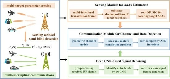
The overall framework of our proposed sensing and deep CNN-assisted semi-blind detection scheme for hybrid massive MU-MIMO systems is summarized in Figure 4, which can be divided into three stages, i.e., target parameter sensing, communication signal denoising and semi-blind detection refinement. In the sensing stage, the BS detects and acquires the azimuth angles of target user equipments (UEs) by sending probing signals and receiving echoes. Then, the uplink communication signals transmitted by UEs are processed in the RF band and denoised by using the pre-trained DnCNN model. Finally, based on the estimated angles and denoised signals, the refined semi-blind detection will be performed at the communication module.
4. Simulation Results
Simulation results are provided in this section to demonstrate the superior performance of the proposed sensing and deep CNN-assisted semi-blind detection scheme. We consider a hybrid massive MU-MIMO system as given in Figure 1, where single-antenna users tend to communicate with the BS-integrated radar and communication modules. For the sensing module, the transmit and receive arrays of radar are equipped with , and the length of snapshots are set to be . For the communication module, the receiver is equipped with antennas and chains. Here, we assume the pilot sequences are mutually orthogonal with the pilot length satisfying . In addition, we choose the payload data independently from the QPSK constellation with unit average power. Moreover, all the scattering and reflection coefficients are supposed to obey the standard complex Gaussian distributions.
4.1. The Proposed Transmission Frame
We firstly compare the channel estimation performance of adopting the multi-functional transmission frame as shown in Figure 2 with some existing schemes, i.e., the conventional pilot-only estimator [39] and the original semi-blind estimator relying solely on the communication module without aid of radar sensing [27]. Specifically, the channel estimation performance is evaluated by the normalized mean squared error (NMSE) defined as . For fair comparison, we assume the process of solving the low-rank matrix completion in Algorithm 1 is temporarily replaced by the same ALS iteration as derived in [27], and the noise variance is approximated according to with being the average received power. The other configurations for the transmission frame are set as , and . Unless otherwise stated, each simulation result is obtained through Monte-Carlo with 1000 independent channel realizations. Figure 5 depicts the NMSE performance versus SNR by using different transmission schemes. We can observe that the proposed sensing-assisted scheme shows significant performance gains especially with low SNRs compared to the alternative estimators, which thanks to that more geometric information about the scattering environments can be gleaned from the target sensing stage, while the other two schemes neglect the structural characteristics of the multi-path channel models.
To further validate the superiority of utilizing radar sensing function to yield the target angles rather than extracting the path angles from the roughly estimated channels as conducted in [30], which designed a three-stage estimator (denoted by “TSTE”) and suggested to obtain the knowledge of array responses directly from an initial low-rank channel estimate, Figure 6 illustrates the root mean squared error (RMSE) defined as to measure the performance of AoAs resolutions of target users by using different detection schemes. Since the estimation deviation of the subspace decomposition-based method mainly depends on the dimension of received covariance matrix and some preset parameters such as the array spacing, we consider two settings of . It can be seen that the proposed sensing-assisted detection scheme achieves better resolutions, especially when the inter-element spacing is larger. Moreover, it is noteworthy that the RMSE under our proposed scheme would improve as the SNR increases, while that obtained by the TSTE estimator only fluctuates slightly versus different SNR, which is reasonable because their path angles are learned from the low-rank matrix solutions instead of straight from the received echoes, and the noise components have been removed before constructing the signal subspaces.
4.2. Refined Semi-Blind Detection
Next, we illustrate the performance gain of our proposed Algorithm 1. To show the advantage of performing semi-blind detection at the receiver rather than the LS/LMMSE-based detection [37], suppose the comparison experiment is set as performing the LMMSE channel estimation after obtaining the knowledge of target angles from the sensing module. Considering two settings of pilot length, and , Figure 7 plots the NMSE performance of channel estimation with different receiver schemes. From Figure 7, we observe that the NMSE performance of Algorithm 1 outperforms the LMMSE method even if the sensing module is involved, which indicates the necessity of exploiting low-rank characteristics in massive MIMO systems to improve the estimation accuracy with relatively lower pilots. In addition, we can note that the NMSE performance of Algorithm 1 improves as the length of data sequences increases, while the performance of LMMSE remains almost the same in all settings. The reason is that by incorporating data into the decomposition process of received signals, Algorithm 1 can take full advantage of payload data as “virtual pilots” to glean more useful information over the conventional pilot-only method.
We then characterize the performances of Algorithm 1 in terms of the computational efficiency and the estimation accuracy without any prior knowledge of channel or noise statistics. By fixing and , Figure 8 depicts the convergence rates by employing different types of iterations, where “R-ALS iteration” refers to the regularized alternating least squares approach proposed by [27] for solving the formulated low-rank matrix completion problem (26). As shown in Figure 8, both the ASD iterations presented in Algorithm 1 and the R-ALS iterations will converge within limited iterations, and their convergence behaviors are similar for different SNR levels. Although the convergence rate of R-ALS iterations seems faster that that of ASD iterations, the calculations of and in Algorithm 1 avoid two matrix inversion operations for each iteration, which would otherwise involve additional complexity with cubic order of the matrix dimension, i.e., . Therefore, the total computational overhead incurred by Algorithm 1 can be relatively reduced especially with high-dimensional matrices.
To further validate the computational complexity of the proposed ASD approach, we conduct more experiments compared with the conventional LMMSE and R-ALS, focusing on their execution time and memory consumption. Following the principles of controlled variable experimental methodology, and with reference to the results illustrated in Figure 7 and Figure 8, we initially quantify the averaged computational cost for all three approaches, under the conditions of and the number of iterations set to 6. Subsequently, given that the LMMSE approach would induce a single execution at the receiver adhered to Equations (12) and (13) without convergence issues, we only record the time and memory expenditures for the proposed ASD and R-ALS iterations by establishing the termination criterion as . The outcomes are presented in Table 3, from which we can observe that the proposed ASD approach exhibits lower time and memory consumption compared to its existing alternatives, thereby demonstrating the advantages in reduced complexity and higher computational efficiency.
In order to visualize the influence with unknown prior knowledge on the estimation accuracy, Figure 9 compares the NMSE performance versus different SNRs by adopting Algorithm 1 and the R-ALS-based estimator, which mimics and modifies the process in [27] given the target angles. For the former scenarios without available noise, the maximum iteration number is set to be ; while for the latter, the regularization parameters used to incorporate the prior information are set to be consistent with the noise variance. It can be seen that benefiting from taking noise effect into account, the R-ALS estimator performs better with low SNR values, which is owing to the non-negligible noise that imposes great challenges on accurate estimations in such SNR ranges. Nevertheless, the performance differences between two algorithms become narrow as the SNR increases, and Algorithm 1 would even achieve better performance under the condition of higher SNRs. By combining the results in Figure 8 and Table 3, we can conclude that our proposed Algorithm 1 is a good choice for refining semi-blind detection due to its comparable performance and lower complexity.
4.3. Signal Denoising by DnCNN
Finally, we confirm the effectiveness of signal denoising by DnCNN before performing semi-blind detection in low SNR regions. To evaluate the denoising performance of adopting different DnCNN models for our received signal dataset, we select the pre-trained DnCNN models in [43] for Gaussian denoising with specific noise levels (which are referred to as DnCNN-15 and DnCNN-25) and for blind Gaussian denoising (which is referred to as DnCNN-B) as comparisons. During the denoising phase, we successively obtain the output as the denoised data of the input . Suppose the clean signal that refers to is related to the combined results of , then the following performance metrics include NMSE and NMSE-Y defined as NMSE-Y = , which are used to measure the accuracy of channel estimation and signal denoising, respectively.
The averaged NMSE and NMSE-Y results over 1000 samples by adopting different signal denoising models are shown in Table 4, where the best results for each SNR value are highlighted in bold. As one can see, all the selected DnCNN models outperform the competing method without signal denoising when SNR is below dB due to the consideration of noise influence in low SNR regions. In contrast, as the noise level decreases, both DnCNN-25 and DnCNN-B produce better results on NMSE-Y while fail to reach higher estimation accuracy, which is intuitively reasonable because the models with strong denoising power are likely to distort the original signal structures. It is pleasant to find that the model DnCNN-15, which is trained with lower noise level, can not only yield the best denoising performance on most of the discussed SNRs but also generate better channel estimates, which indicates the feasibility of deploying the signal denoising before performing the semi-blind detection.
5. Conclusions
In this paper, we have proposed a sensing and deep CNN-assisted semi-blind detection refinement scheme for uplink hybrid massive MU-MIMO systems. The main idea is to extract the geometric structure corresponding to the communication channels via radar sensing, based on which both the transmitted pilot and payload data are contributed to yield the refined estimates. We have treated the signal recovery problem as acquiring factorization solutions to a low-rank matrix completion, for which an iterative algorithm modified from ASD is presented without any prior knowledge of noise statistics. Specifically, a pre-trained DnCNN has been adopted for signal denoising to alleviate the noise enhancement along with the LS-based estimation process, especially in low SNR regions. The overall approach has been carried out in three progressive stages, i.e., target parameter sensing, communication signal denoising and semi-blind detection refinement. Consequently, simulation results have been provided to validate the superior performance of our proposed scheme. It is seen that the utilization of co-designed multi-functional transmission frame and the refined semi-blind receiver could achieve better estimation accuracy with reduced training overhead, which facilitates the availability of sensing-assisted communications.
Despite the advancements introduced by the proposed architecture, focusing on leveraging radar sensing capabilities to enhance communication gains, there still remain several limitations requiring further investigation. Instead of relying on the coexistence and information sharing between different modules, future work could develop more powerful signal processing techniques to integrate radar and communication modules into a unified hardware platform and decongest the RF environment by using the same signal for both functionalities. In such a case, devising sophisticated signal models that harmoniously incorporate the distinctions between LoS and multi-path channels might unveil new dimensions of system performance.
Another crucial aspect that needs to be considered in future work involves the time-varying property of propagation paths under user mobility scenarios, including time-delay parameters and Doppler shift effects. This aspect necessitates the BS to pre-compensate for these effects before demodulating the received signals for most robust detection performance. Toward this end, we plan to explore the time-varying channel tracking algorithms and compensation methods to mitigate the adverse effects of temporal fluctuations and phase deviations on estimation errors, which should be of great importance to cater to real-time applications.
Author Contributions
Conceptualization, F.H. and J.Z.; methodology, F.H. and L.Z.; software, H.Z. and J.W.; validation, J.Z. and J.W.; formal analysis, H.Z. and L.Z.; investigation, F.H.; resources, L.Z. and H.Z.; data curation, J.Z. and J.W.; writing—original draft preparation, F.H.; writing—review and editing, L.Z. and H.Z.; visualization, J.W.; supervision, J.Z.; project administration, F.H.; funding acquisition, F.H. All authors have read and agreed to the published version of the manuscript.
Funding
This research was funded in part by the National Natural Science Foundation of China under Grants 62201388 and 62201389, in part by the Natural Science Foundation of Shanghai under Grant 22ZR1463400 and in part by the Fundamental Research Funds for the Central Universities under Grant 2022-5-YB-01.
Data Availability Statement
The data are not publicly available due to privacy.
Conflicts of Interest
The authors declare no conflicts of interest.
References
- Tong, W.; Li, G.Y. Nine challenges in artificial intelligence and wireless communications for 6G. IEEE Wirel. Commun. 2022, 29, 140–145. [Google Scholar] [CrossRef]
- Li, X.; Liu, F.; Zhou, Z.; Zhu, G.; Wang, S.; Huang, K.; Gong, Y. Integrated sensing, communication, and computation over-the-Air: MIMO beamforming design. IEEE Trans. Wirel. Commun. 2023, 22, 5383–5398. [Google Scholar] [CrossRef]
- Koubaa, A.; Ammar, A.; Abdelkader, M.; Alhabashi, Y.; Ghouti, L. AERO: AI-enabled remote sensing observation with onboard edge computing in UAVs. Remote Sens. 2023, 15, 1873. [Google Scholar] [CrossRef]
- Zhu, Y.; Guo, H.; Lau, V.K.N. Bayesian channel estimation in multi-user massive MIMO with extremely large antenna array. IEEE Trans. Signal Process. 2021, 69, 5463–5478. [Google Scholar] [CrossRef]
- Guo, J.; Wen, C.-K.; Jin, S.; Li, G.Y. Overview of deep learning-based CSI feedback in massive MIMO systems. IEEE Trans. Commun. 2022, 70, 8017–8045. [Google Scholar] [CrossRef]
- Zhang, R.; Cheng, L.; Wang, S.; Lou, Y.; Wu, W.; Ng, D.W.K. Tensor decomposition-based channel estimation for hybrid mmWave massive MIMO in high-mobility scenarios. IEEE Trans. Commun. 2022, 70, 6325–6340. [Google Scholar] [CrossRef]
- Wei, X.; Hu, C.; Dai, L. Deep learning for beamspace channel estimation in millimeter-wave massive MIMO systems. IEEE Trans. Commun. 2021, 69, 182–193. [Google Scholar] [CrossRef]
- Nguyen, N.T.; Ma, M.; Lavi, O.; Shlezinger, N.; Eldar, Y.C.; Swindlehurst, A.L.; Juntti, M. Deep unfolding hybrid beamforming designs for THz massive MIMO systems. IEEE Trans. Signal Process. 2023, 71, 3788–3804. [Google Scholar] [CrossRef]
- Mirzaei, J.; ShahbazPanahi, S.; Sohrabi, F.; Adve, R. Hybrid analog and digital beamforming design for channel estimation in correlated massive MIMO systems. IEEE Trans. Signal Process. 2021, 69, 5784–5800. [Google Scholar] [CrossRef]
- Wei, X.; Dai, L. Channel estimation for extremely large-scale massive MIMO: Far-field, near-field, or hybrid-field? IEEE Commun. Lett. 2022, 26, 177–181. [Google Scholar] [CrossRef]
- Chafaa, I.; Negrel, R.; Belmega, E.V.; Debbah, M. Self-supervised deep learning for mmWave beam steering exploiting sub-6 GHz channels. IEEE Trans. Wirel. Commun. 2022, 21, 8803–8816. [Google Scholar] [CrossRef]
- Wu, K.; Zhang, J.A.; Huang, X.; Guo, Y.J.; Hanzo, L. Simultaneous beam and user selection for the beamspace mmWave/THz massive MIMO downlink. IEEE Trans. Commun. 2023, 71, 1785–1797. [Google Scholar] [CrossRef]
- Cheng, Z.; Liao, B. QoS-aware hybrid beamforming and DOA estimation in multi-carrier dual-function radar-communication systems. IEEE J. Sel. Areas Commun. 2022, 40, 1890–1905. [Google Scholar] [CrossRef]
- Liu, F.; Cui, Y.; Masouros, C.; Xu, J.; Han, T.X.; Eldar, Y.C.; Buzzi, S. Integrated sensing and communications: Toward dual-functional wireless networks for 6G and beyond. IEEE J. Sel. Areas Commun. 2022, 40, 1728–1767. [Google Scholar] [CrossRef]
- Cui, Y.; Liu, F.; Jing, X.; Mu, J. Integrating sensing and communications for ubiquitous IoT: Applications, trends, and challenges. IEEE Netw. 2021, 35, 158–167. [Google Scholar] [CrossRef]
- Wang, J.; Varshney, N.; Gentile, C.; Blandino, S.; Chuang, J.; Golmie, N. Integrated Sensing and Communication: Enabling Techniques, Applications, Tools and Data Sets, Standardization, and Future Directions. IEEE Internet Things J. 2022, 9, 23416–23440. [Google Scholar] [CrossRef]
- Graff, A.; Chen, Y.; González-Prelcic, N.; Shimizu, T. Deep learning-based link configuration for radar-aided multiuser mmWave vehicle-to-infrastructure communication. IEEE Trans. Veh. Technol. 2023, 72, 7454–7468. [Google Scholar] [CrossRef]
- Wang, X.; Zhai, W.; Zhang, X.; Wang, X.; Amin, M.G. Enhanced automotive sensing assisted by joint communication and cognitive sparse MIMO radar. IEEE Trans. Aerosp. Electron. Syst. 2023, 59, 4782–4799. [Google Scholar] [CrossRef]
- Hassan, K.; Masarra, M.; Zwingelstein, M.; Dayoub, I. Channel estimation techniques for millimeter-wave communication systems: Achievements and challenges. IEEE Open J. Commun. Soc. 2020, 1, 1336–1363. [Google Scholar] [CrossRef]
- Zhang, R.; Yang, L.; Tang, M.; Tan, W.; Zhao, J. Channel estimation for mmWave massive MIMO systems with mixed-ADC architecture. IEEE Open J. Commun. Soc. 2023, 4, 606–613. [Google Scholar] [CrossRef]
- Wang, Y.; Zhang, Y.; Tian, Z.; Leus, G.; Zhang, G. Super-resolution channel estimation for arbitrary arrays in hybrid millimeter-wave massive MIMO systems. IEEE J. Sel. Top. Signal Process. 2019, 13, 947–960. [Google Scholar] [CrossRef]
- Fan, D.; Gao, F.; Liu, Y.; Deng, Y.; Wang, G.; Zhong, Z.; Nallanathan, A. Angle domain channel estimation in hybrid millimeter wave massive MIMO systems. IEEE Trans. Wirel. Commun. 2018, 17, 8165–8179. [Google Scholar] [CrossRef]
- Zhou, L.; Dai, J.; Xu, W.; Chang, C. Sparse channel estimation for intelligent reflecting surface assisted massive MIMO systems. IEEE Trans. Green Commun. Netw. 2022, 6, 208–220. [Google Scholar] [CrossRef]
- Wang, Y.; Qi, C.; Li, P.; Lu, Z.; Lu, P. Channel estimation for wideband mmWave MIMO OFDM system exploiting block sparsity. IEEE Commun. Lett. 2022, 26, 897–901. [Google Scholar] [CrossRef]
- Chu, H.; Zheng, L.; Wang, X. Semi-blind millimeter-wave channel estimation using atomic norm minimization. IEEE Commun. Lett. 2018, 22, 2535–2538. [Google Scholar] [CrossRef]
- Han, F.; Wang, X.; Deng, H. A very-low pilot scheme for mmWave hybrid massive MIMO-OFDM systems. IEEE Wirel. Commun. Lett. 2021, 10, 2061–2064. [Google Scholar] [CrossRef]
- Liang, S.; Wang, X.; Ping, L. Semi-blind detection in hybrid massive MIMO systems via low-rank matrix completion. IEEE Trans. Wirel. Commun. 2019, 18, 5242–5254. [Google Scholar] [CrossRef]
- Li, X.; Fang, J.; Li, H.; Wang, P. Millimeter wave channel estimation via exploiting joint sparse and low-rank structures. IEEE Trans. Wirel. Commun. 2018, 17, 1123–1133. [Google Scholar] [CrossRef]
- Vlachos, E.; Alexandropoulos, G.C.; Thompson, J. Massive MIMO channel estimation for millimeter wave systems via matrix completion. IEEE Signal Process. Lett. 2018, 25, 1675–1679. [Google Scholar] [CrossRef]
- Masood, K.F.; Hu, R.; Tong, J.; Xi, J.; Guo, Q.; Yu, Y. A low-complexity three-stage estimator for low-rank mmWave channels. IEEE Trans. Veh. Technol. 2021, 70, 5920–5931. [Google Scholar] [CrossRef]
- Nguyen, L.T.; Kim, J.; Shim, B. Low-rank matrix completion: A contemporary survey. IEEE Access 2019, 7, 94215–94237. [Google Scholar] [CrossRef]
- Giampouras, P.V.; Rontogiannis, A.A.; Koutroumbas, K.D. Alternating iteratively reweighted least squares minimization for low-rank matrix factorization. IEEE Trans. Signal Process. 2019, 67, 490–503. [Google Scholar] [CrossRef]
- Chi, Y.; Lu, Y.M.; Chen, Y. Nonconvex optimization meets low-rank matrix factorization: An overview. IEEE Trans. Signal Process. 2019, 67, 5239–5269. [Google Scholar] [CrossRef]
- Tanner, J.; Wei, K. Low rank matrix completion by alternating steepest descent methods. Appl. Comput. Harmon. Anal. 2016, 40, 417–429. [Google Scholar] [CrossRef]
- Liu, F.; Masouros, C.; Petropulu, A.P.; Griffiths, H.; Hanzo, L. Joint radar and communication design: Applications, state-of-the-art, and the road ahead. IEEE Trans. Commun. 2020, 68, 3834–3862. [Google Scholar] [CrossRef]
- Yuan, W.; Wei, Z.; Li, S.; Yuan, J.; Ng, D.W.K. Integrated sensing and communication-assisted orthogonal time frequency space transmission for vehicular networks. IEEE J. Sel. Top. Signal Process. 2021, 15, 1515–1528. [Google Scholar] [CrossRef]
- Huang, S.; Zhang, M.; Gao, Y.; Feng, Z. MIMO radar aided mmWave time-varying channel estimation in MU-MIMO V2X communications. IEEE Trans. Wirel. Commun. 2021, 20, 7581–7594. [Google Scholar] [CrossRef]
- He, H.; Wen, C.-K.; Jin, S.; Li, G.Y. Deep learning-based channel estimation for beamspace mmWave massive MIMO systems. IEEE Wirel. Commun. Lett. 2018, 7, 852–855. [Google Scholar] [CrossRef]
- Kay, S.M. Fundamentals of Statistical Signal Processing, Volume III: Practical Algorithm Development; Prentice Hall: Upper Saddle River, NJ, USA, 2013. [Google Scholar]
- Gizzini, A.K.; Chafii, M.; Nimr, A.; Fettweis, G. Enhancing least square channel estimation using deep learning. In Proceedings of the 2020 IEEE 91st Vehicular Technology Conference: VTC2020-Spring, Antwerp, Belgium, 25–28 May 2020; pp. 1–5. [Google Scholar]
- Schmidt, R. Multiple emitter location and signal parameter estimation. IEEE Trans. Antennas Propag. 1986, 34, 276–280. [Google Scholar] [CrossRef]
- Liu, A.; Lau, V. Phase only RF precoding for massive MIMO systems with limited RF chains. IEEE Trans. Signal Process. 2014, 62, 4505–4515. [Google Scholar] [CrossRef]
- Zhang, K.; Zuo, W.; Chen, Y.; Meng, D.; Zhang, L. Beyond a gaussian denoiser: Residual learning of deep CNN for image denoising. IEEE Trans. Image Process. 2017, 26, 3142–3155. [Google Scholar] [CrossRef] [PubMed]
Figure 1.
Sensing-assisted hybrid massive MU-MIMO communication system. The blue solid lines denote the probing signal sent by the sensing module. The red solid lines denote the corresponding echoes reflected by target users. The green dashed lines denote the uplink communication signals.
Figure 1.
Sensing-assisted hybrid massive MU-MIMO communication system. The blue solid lines denote the probing signal sent by the sensing module. The red solid lines denote the corresponding echoes reflected by target users. The green dashed lines denote the uplink communication signals.

Figure 2.
The structure of multi-functional transmission frame. denotes the duration of transmitted waveform by radar module. and denote the duration of uplink pilots and payload data, respectively.
Figure 2.
The structure of multi-functional transmission frame. denotes the duration of transmitted waveform by radar module. and denote the duration of uplink pilots and payload data, respectively.

Figure 3.
Comparisons among sample signals of (a) Gaussian noise, (b) our signal and (c) natural image, with corresponding histograms in (d), (e), (f), respectively. (e) exhibits similar distribution with (d), while (f) is distinct from (d).
Figure 3.
Comparisons among sample signals of (a) Gaussian noise, (b) our signal and (c) natural image, with corresponding histograms in (d), (e), (f), respectively. (e) exhibits similar distribution with (d), while (f) is distinct from (d).

Figure 4.
The overall framework of the proposed sensing and deep CNN-assisted semi-blind detection.

Figure 5.
The NMSE performance versus SNR by using different transmission schemes.

Figure 6.
The detection performance of AoAs resolutions under different schemes.

Figure 7.
The NMSE performance versus length of data sequences under different receiver schemes with .
Figure 7.
The NMSE performance versus length of data sequences under different receiver schemes with .

Figure 8.
Convergence rates of adopting different iterative algorithms, where with .

Figure 9.
The NMSE performance versus SNR by adopting different iterative algorithms.


Table 1.
Existing works comparison on receiver techniques.
| Existing Works | System Models | Receiver Techniques | Limitations or Features |
|---|---|---|---|
| [19,20,21] | mmWave MIMO communications | non-blind detection based on pilots only | Pilot overhead can be enlarged greatly with massive antennas. |
| [22,23,24] | mmWave MIMO communications | CS leveraging the channel sparsity | Gird-based estimator may lead to effects of basis mismatch. |
| [25] | mmWave MIMO communications | atomic norm minimization | High-dimensional optimizations may cause substantial computational complexity. |
| [26] | mmWave MIMO communications | semi-blind detection aided with payload data | Neglect of geometric structure of channel distributions. |
| [27] | massive MIMO communications | LS leveraging the channel low-rankness | Underexploitation of realistic channel characteristic with multiple propagation paths. |
| [28,29,30] | mmWave MIMO communications | multiple stages exploiting both the low-rankness and sparsity | High computational complexity when generalized to large-scale problems. |
| [35] | joint radar and communications | multiple signal classification (MUSIC) for angle estimation | Joint signal processing strategy can simultaneously detect targets while estimating the communication channel. |
| [36] | joint radar and communications | maximum likelihood (ML) estimator | Sensing parameter estimation can promote the dynamic topology construction of surrounding environments. |
| [37] | joint radar and communications | LS detection vs. DL-based denoiser | Efficient estimation with fewer training resources by eliminating noise before recovering channels. |
Table 2.
List of acronyms.
| Abbreviations | Expansion |
|---|---|
| ALS | Alternating Least Squares |
| AoA | Angle-of-Arrival |
| AoD | Angle-of-Departure |
| BS | Base Station |
| CNN | Convolutional Neural Network |
| CS | Compressed Sensing |
| DnCNN | Denoising Convolutional Neural Network |
| DL | Deep Learning |
| LMMSE | Linear Minimum Mean Squared Error |
| LoS | Line-of-Sight |
| LS | Least Squares |
| mmWave | Millimeter Wave |
| MIMO | Multiple-Input Multiple-Output |
| MU-MIMO | Multi-User MIMO |
| MUSIC | Multiple Signal Classification |
| NMSE | Normalized Mean Squared Error |
| RF | Radio Frequency |
| RMSE | Root Mean Squared Error |
| SNR | Signal-to-Noise Ratio |
| SVD | Singular Value Decomposition |
| TDD | Time-Division Duplex |
| UE | User Equipment |
| ULA | Uniform Linear Array |
Table 3.
Comparisons on computational cost by using different approaches.
| Approaches | Averaged Computational Cost | Total Cost until Convergence | ||
|---|---|---|---|---|
| performance | memory | time | memory | time |
| proposed ASD | 0.216 Kb | 3.11 ms | 10.22 Kb | 22.80 ms |
| R-ALS | 8.644 Kb | 43.22 ms | 46.61 Kb | 86.96 ms |
| LMMSE | 0.636 Kb | 3.50 ms | / | / |
Table 4.
Performance comparison by adopting different signal denoising models.
| SNR Value | −5 dB | −4 dB | −3 dB | |||
|---|---|---|---|---|---|---|
| Selected Model | NMSE-Y | NMSE | NMSE-Y | NMSE | NMSE-Y | NMSE |
| Without DnCNN | 3.1727 | 1.6561 | 2.5430 | 1.2967 | 1.9962 | 0.9956 |
| DnCNN-15 | 1.5223 | 1.0362 | 1.1352 | 0.8159 | 0.8320 | 0.6679 |
| DnCNN-25 | 0.8566 | 0.8875 | 0.8618 | 0.8951 | 0.8888 | 0.9199 |
| DnCNN-B | 0.9424 | 0.9635 | 0.9265 | 0.9488 | 0.8888 | 0.9042 |
| SNR Value | −2 dB | −1 dB | 0 dB | |||
| Selected Model | NMSE-Y | NMSE | NMSE-Y | NMSE | NMSE-Y | NMSE |
| Without DnCNN | 1.6025 | 0.8733 | 1.2425 | 0.7477 | 0.9951 | 0.6051 |
| DnCNN-15 | 0.6335 | 0.6242 | 0.4998 | 0.5947 | 0.4312 | 0.5720 |
| DnCNN-25 | 0.9070 | 0.9363 | 0.9314 | 0.9552 | 0.9356 | 0.9610 |
| DnCNN-B | 0.9350 | 0.8631 | 0.8218 | 0.8875 | 0.7700 | 0.8672 |
Disclaimer/Publisher’s Note: The statements, opinions and data contained in all publications are solely those of the individual author(s) and contributor(s) and not of MDPI and/or the editor(s). MDPI and/or the editor(s) disclaim responsibility for any injury to people or property resulting from any ideas, methods, instructions or products referred to in the content. |
© 2024 by the authors. Licensee MDPI, Basel, Switzerland. This article is an open access article distributed under the terms and conditions of the Creative Commons Attribution (CC BY) license (https://creativecommons.org/licenses/by/4.0/).
Share and Cite
MDPI and ACS Style
Han, F.; Zeng, J.; Zheng, L.; Zhang, H.; Wang, J. Sensing and Deep CNN-Assisted Semi-Blind Detection for Multi-User Massive MIMO Communications. Remote Sens. 2024, 16, 247. https://0-doi-org.brum.beds.ac.uk/10.3390/rs16020247
AMA Style
Han F, Zeng J, Zheng L, Zhang H, Wang J. Sensing and Deep CNN-Assisted Semi-Blind Detection for Multi-User Massive MIMO Communications. Remote Sensing. 2024; 16(2):247. https://0-doi-org.brum.beds.ac.uk/10.3390/rs16020247
Chicago/Turabian StyleHan, Fengxia, Jin Zeng, Le Zheng, Hongming Zhang, and Jianhui Wang. 2024. "Sensing and Deep CNN-Assisted Semi-Blind Detection for Multi-User Massive MIMO Communications" Remote Sensing 16, no. 2: 247. https://0-doi-org.brum.beds.ac.uk/10.3390/rs16020247
Note that from the first issue of 2016, this journal uses article numbers instead of page numbers. See further details here.