1. Introduction
Different connection methods are used for modular structures depending on the main materials that the modules are composed of, their shape, and the method of load transfer. In the research conducted by Lawson et al. [
1], steel was the main module material, and box type frames with columns and beams were the conventional module shapes. Mills et al. [
2] described stacking modules to fabricate low-rise buildings, with stabilization systems such as braces added for medium-rise buildings, and lateral force-resisting systems (such as concrete cores or reinforcement frames) used for high-rise buildings. For steel-framed buildings, the lateral force has to be resisted as well as the gravitational load, and the number of stacked modules is limited if there is no separate lateral force-resisting system.
Because the behavior of connections in steel frame structures can affect the distribution of member forces and deformation shapes, connection behavior is considered significant in analysis and design. Generally, connection behavior can be evaluated in terms of strength, stiffness, and deformation capability. Connections can be the weakest components, and thus may determine the bearing strength capacity of the structural system. Hence, connections are considered important components [
3].
In modular structures, the overall structural system is composed of units that are interconnected or connected to separate lateral force-resisting systems. Therefore, the beam–column connection used to construct a unit has to be able to transfer the gravitational load onto the slab. In the case of low-rise structures where the lateral load is resisted only by the modular units, sufficient lateral stiffness is necessary so that the internal forces of an individual member can be exerted. Connections between modular units that make up the entire framing system should have sufficient strength capacity and stiffness to transfer the lateral force to the surrounding modules and guarantee the stability of the entire structure.
In conventional modular systems, rectangular tubes or channels are generally used for the columns, and channels are used for beam members [
4,
5]. However, in current systems, although the specifications of connections between units can vary depending on the scope of the module interior and exterior, as well as the construction error [
5], modular units are generally connected using bolts [
6,
7,
8,
9], interlocking devices [
10,
11,
12], and steel plate welding [
13]. However, these methods are not technically or practically suitable for all types of modular buildings, such as high-rise modular buildings.
Here, we describe a novel technology for connecting modular units that can ensure the safety of modular structures. In this study, connections using straight and cross-shaped metal connectors between modules that use rectangular tubular columns and channel beams are proposed. Their structural performance, in terms of strength, stiffness, and deformation capability, is evaluated through cyclic loading tests by controlling the story drift angle of the modular units in both the width and longitudinal directions.
2. Overview of Current Methods for Connecting Modular Units
Current methods for connecting units are very diverse and vary with module composition and the overall structural system of the modular building. Therefore, this investigation was limited to connections between framed units. The characteristics of such connections are determined by the interior and exterior material finish and the construction error [
5].
2.1. Bolt Connection Using Connector Plates
Inserting a connector plate between modules and connecting them with bolts is the most widely used method for connecting upper and lower units and left and right units. Depending on the layout of the units, four or eight upper–lower and left–right modules may meet at a single point.
In the connection system for Toyota Home [
7], a hash-shaped (#) connector plate is used to connect eight modules. The protruding guide pin enables coordination with the upper module. At least one of the four modules to be positioned above must have an opening that can act as a service opening or an access hole for bolting. As these openings must be finished on site, the building is obviously affected by the site finishing work when using this modular method.
In the Sekisui Heim system [
8] for connecting modules, the upper and lower modules are connected by friction bolts using small steel blocks at the boundary, while a steel plate is added for bolting the left and right modules. Similarly, to connect units, part of the ceiling of the lower module and part of the corner floor of the upper module must be finished on site after connection.
The VectorBloc system [
9] is for high-rise buildings developed in the USA by Vector Praxis. Blocks produced by casting are welded to the ends of the floor and ceiling beams of the module, and a connector plate is inserted between the upper and lower modules and connected by tightening the bolt from the floor of the upper module. The block welded to the ceiling beam also functions as a nut, and fastening is performed from top to bottom from the inside, and thus safety and constructability are guaranteed. Additionally, the module units and connection system are precisely manufactured, with an error of approximately 2 mm per 100 m.
For methods where units are connected from inside the module using a connector plate, the connection approach determines the factory finish of the module and significantly impacts the efficiency of the connections. In particular, when a space or gap is left for connection of a module to a concrete slab, the production rate decreases. Thus, whether an opening is left for connection of a module in the ceiling needs to be considered. In addition, when a flat surface is designed to enable connection between modules using a duct or shaft, the constraints imposed by the concrete floor can be minimized.
2.2. Interlocking Method
When stacking modular units, protruding pins on the bottom of the upper module columns, are used for accurate positioning of the upper and lower modules, these also resist the lateral force through interlocking. In the interlocking system used by the Kullman Building Corporation [
10,
11], pins welded to the bottom of the module columns can be used to adjust the location and direction, as well as reduce construction error. The upper and lower modules are coordinated using the interlocking device, and the left and right modules are connected by adding steel plates and using blind bolts. In addition, welding of the left and right modules is conducted using the bolt connection of each module in the beam section in the lower part of the concrete floor, and the steel plates in the ceiling beam section.
Another example of the interlocking method is the connection system used in the Unitised Building [
12]. With this system, the upper and lower modules and left and right modules are connected using exposed columns to the sides of the modules and steel blocks welded to the top and bottom so that the modules interlock horizontally with bolts and rods. There is also a modified method that replaces the steel blocks welded to the top and bottom of the columns with thick plates; a certain amount of space is needed between the left and right modules for connection, as the columns to the sides of the modules are exposed.
While connecting modules from the exterior using interlocking devices is advantageous with regard to the completeness of the interior and exterior finish, space for aerial work is necessary when connecting units at the front and rear surfaces of modules [
10,
11]. There is also the disadvantage of not being able to connect the fourth stacked module at a single nodal point when units are connected via the side of the module [
12].
2.3. Steel Plate Welding
Steel plate welding involves covering the floor and ceiling beams with a steel plate and welding the beams together when the modules are placed against each other [
10,
11]; this method is mainly used for connecting horizontal modules. In the steel plate welding connection used by Capsys Corporation, Whitley East LLC (Leola, PA, USA) [
13], a section of the concrete slab over the expanded corner area is not deposited and forms a rectangular area where the module corners converge. A horizontal connection is established by welding a steel plate on the upper flange of the module beams meeting in this area, and a vertical connection is established through bolting on the lower flange of the floor beams.
When welding is used for connecting units, the interior and exterior finish may be damaged, or “contaminated”, and thus the amount of on-site finishing work required is increased. In addition, there is a high possibility of being limited to horizontal welding depending on the welding position or posture. As a result, there are few examples of welding being used to connect units.
3. Overview of the Proposed Connection Methods and Specimen Design
As detailed in Chapter 2, the specifications of connections between units, including connector plates, can vary depending on the scope of the module interior and exterior, as well as the construction error. In conventional modular buildings, modular units are generally connected using bolts in conjunction with connector plates, interlocking devices, and steel plate welding.
However, current connection systems are not technically or practically suitable for all modular buildings, such as high-rise modular buildings. Here, we describe a novel technology for connecting modular units that can ensure the safety of modular buildings. In this study, straight and cross-shaped metal connectors using rectangular tubular columns and channel beams to connect modules are proposed. If the connectors developed in this study are used, it is possible to connect between modules from inside, rather than from outside the modular building. This is advantageous in terms of construction safety. In addition, the lateral load-resisting capacity of corner section of the modular building will be enhanced if the connectors are installed by applying L- and T-shaped connection systems. Their structural performance is evaluated through cyclic loading tests, in which the story drift angle is controlled in the width and longitudinal directions.
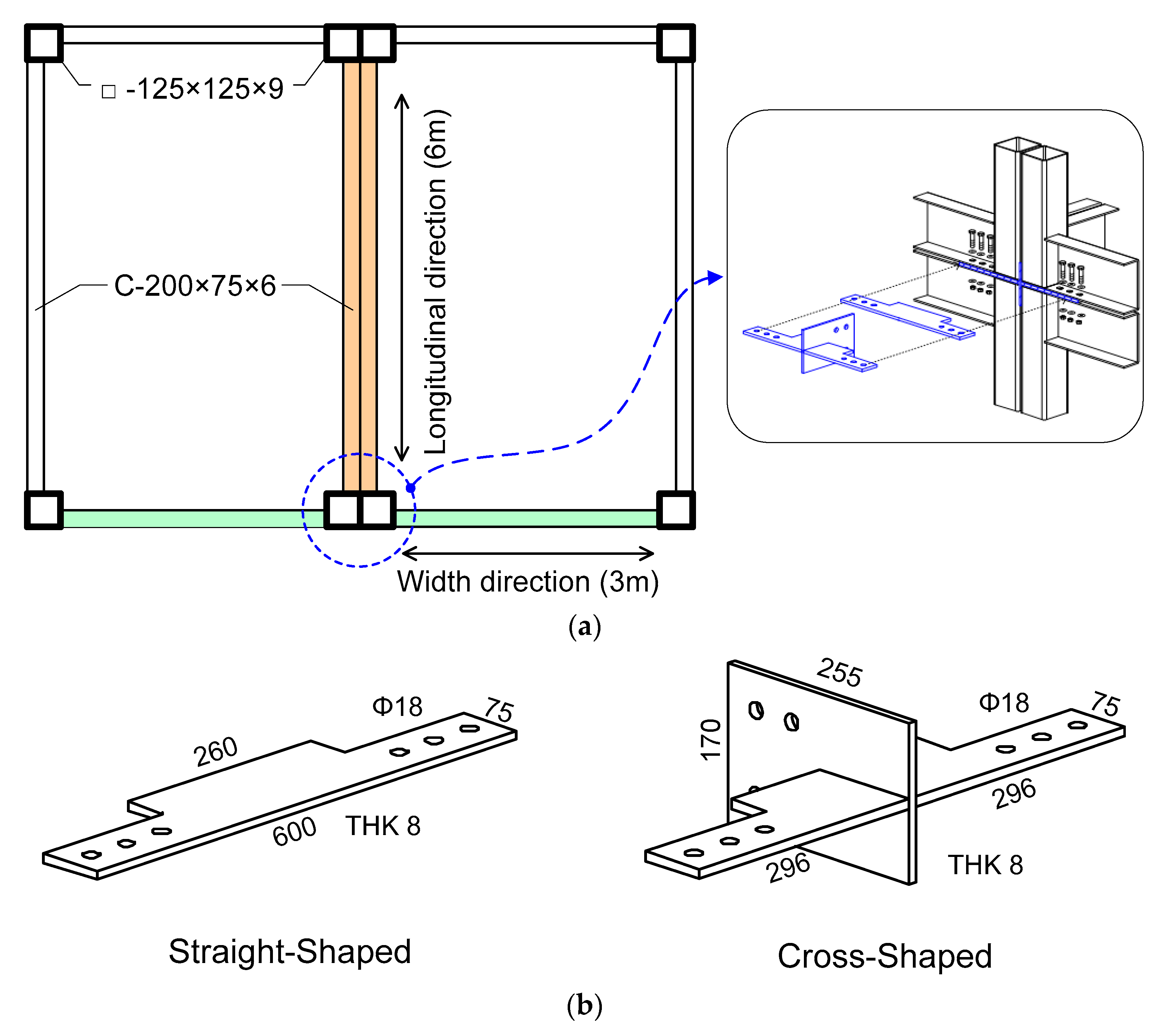
Figure 1 shows the connection method for the modular building system proposed in this study. As shown in
Figure 1a, one modular frame unit consists of a 3 × 6 × 3 m module with 125 × 125 × 9 mm (SPSR400) square tubes as column members and 200 × 75 × 6 mm (SS400) channels as beams. To connect the 3 × 6 × 3 m modules in the up–down and left–right directions, this study proposes a novel system for connecting modular units using straight and cross-shaped connector plates, as shown in
Figure 1b.
As square tubes were used for the columns, the modular unit connections exhibited similar moment–rotation relationships between the width and longitudinal directions, but these relationships can change depending on the connector plate placement direction. Structural performance was evaluated using cyclic loading tests, in which the story drift angle was controlled in the width and longitudinal directions.
The width-to-thickness ratio of the 125 × 125 × 9 mm square tubes was 12.8, which is less than the width-to-thickness ratio limit of 18.9 (=
) for the compression elements of the compact seismic cross-section specified in KBC 2016 [
14]; thus, resistance of the tubes against local buckling was confirmed. The 200 × 75 × 6 mm channel beams were manufactured by bending steel plates in accordance with KS D 3530, “Light Gauge Steels for General Structure” [
15]. The width-to-thickness ratio of the web, being 31.33, was smaller than the seismic compact cross-section slenderness ratio limit of 72.34 (=
), but the flange width-to-thickness ratio of 12.5 was greater than the seismic compact cross-section limit slenderness ratio of 8.86 (=
) and the compact cross-section slenderness ratio limit of 11.22 (= 0.38
), and thus this was categorized as a non-compact cross-section. Therefore, it was necessary to reinforce the stiffener at set intervals to prevent local buckling of the channel beams. In the actual module, the resistance against local buckling should be sufficient, as portions of the channel beam upper flange and web are embedded in the concrete slab.
When connecting modules together using F10T M16 bolts, the straight connector plate is inserted into the 10 mm gap space between the modules in the upper and lower stories. This connection method has the advantage that the parts can be finished in the factory, except for the inter-story layer where the floor beam of the upper story module and ceiling beam of the lower story module meet; it also has the advantage of convenience with respect to securing workspace for bolting, as the beam flange is exposed to the outside.
The method uses a cross-shaped connector plate combined with the three bolts on each of the left and right modules that penetrate the beam flange in the width direction, and the two bolts on each of the upper and lower modules that penetrate the beam web in the longitudinal direction, along with the straight connector plate. Although forming a flange connection in the exposed beam is relatively easy using the cross-shaped connector plate, bolt connection of the web is only possible when there is a shaft in the corner area of the module, or an opening on the lower story module ceiling or upper story module floor.
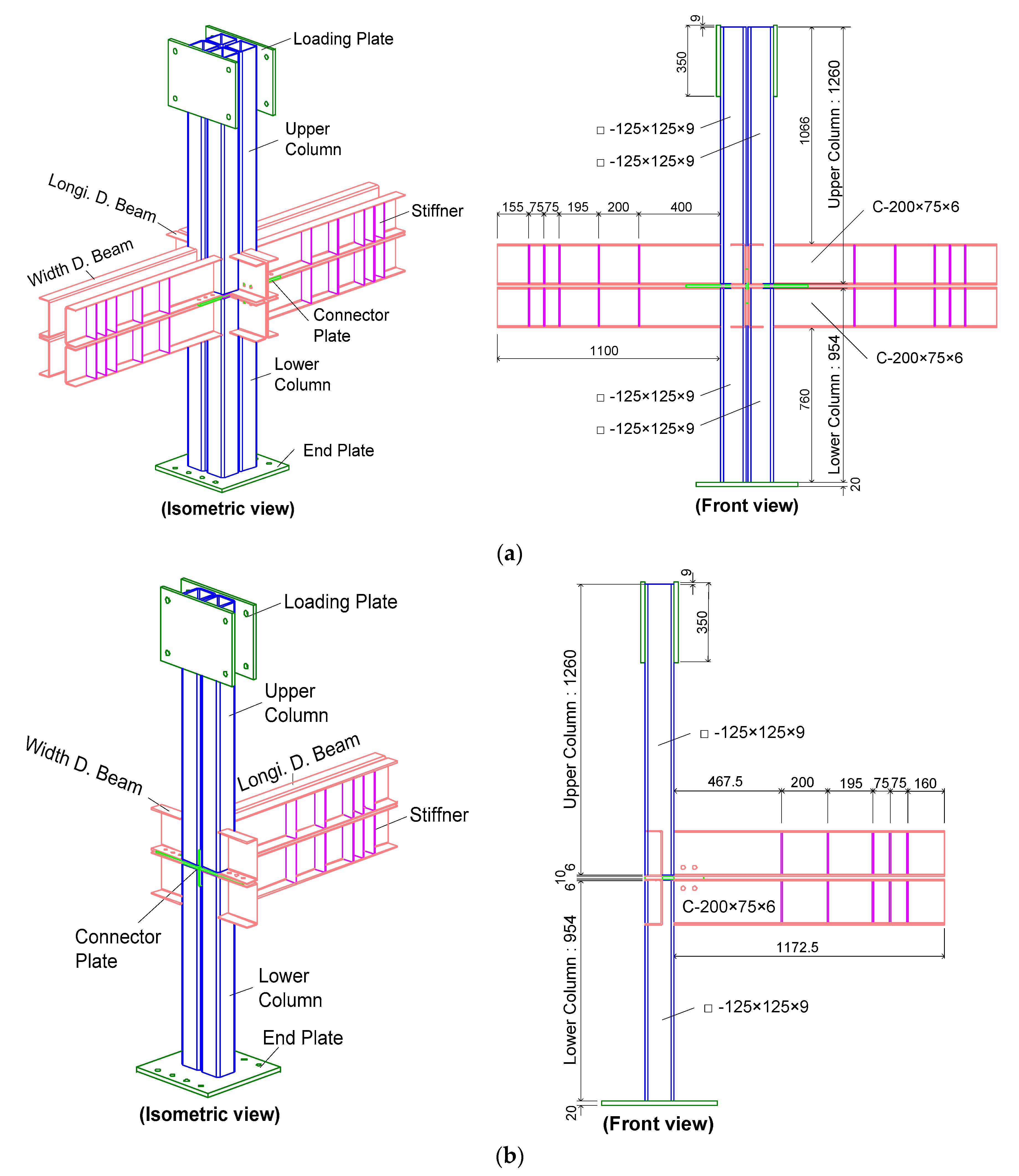
Considering that the beam has an asymmetric cross-section, and that the connection is eccentric to the column, we fabricated specimens to be symmetric, and instability due to eccentric loading was minimized. As shown in
Table 1, cross-shaped specimens were manufactured in the width direction and cantilever specimens were fabricated in the longitudinal direction. A total of four specimens were manufactured, as shown in
Figure 2.
5. Experimental Results: Comparison and Analysis
5.1. Experimental Results
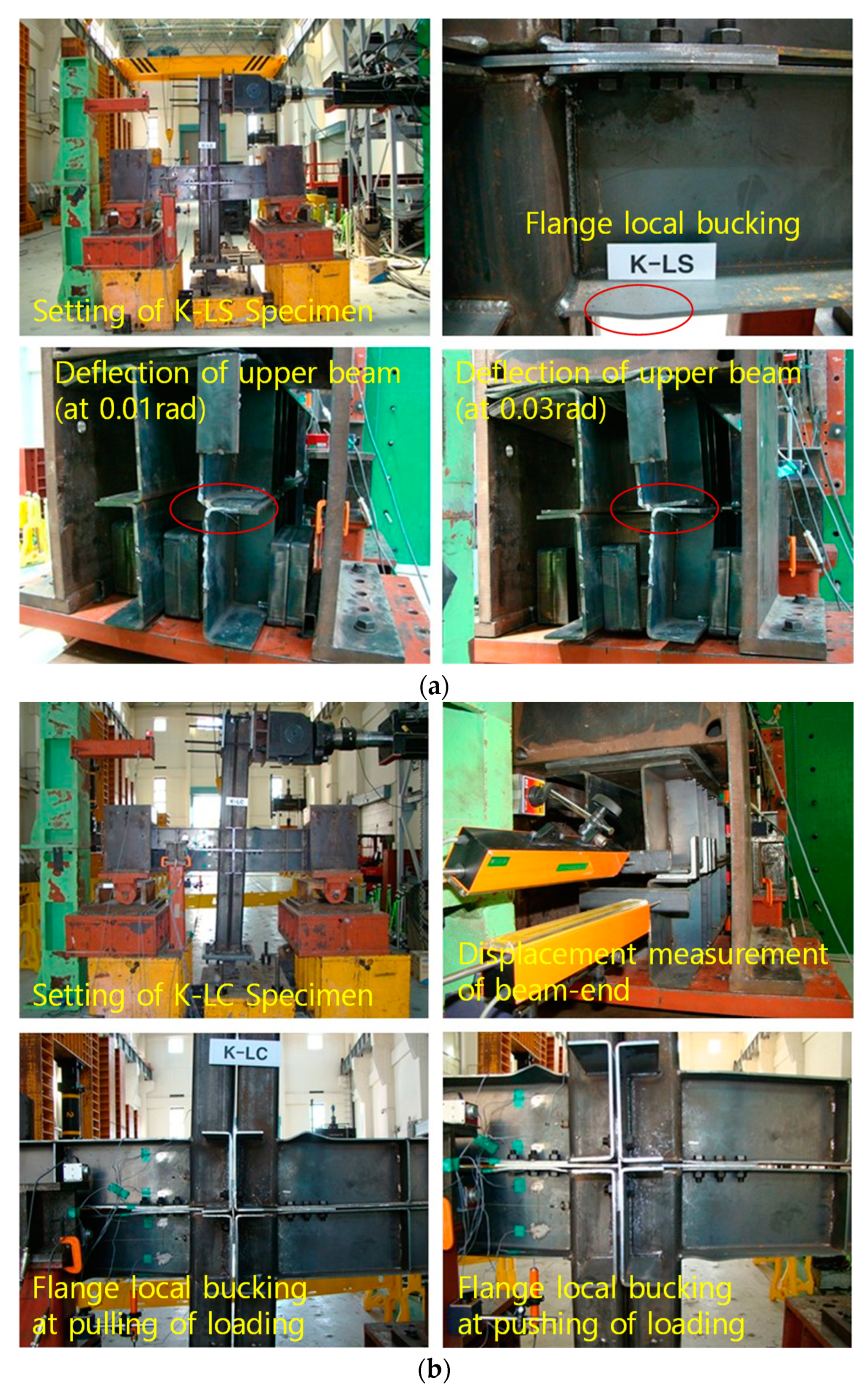
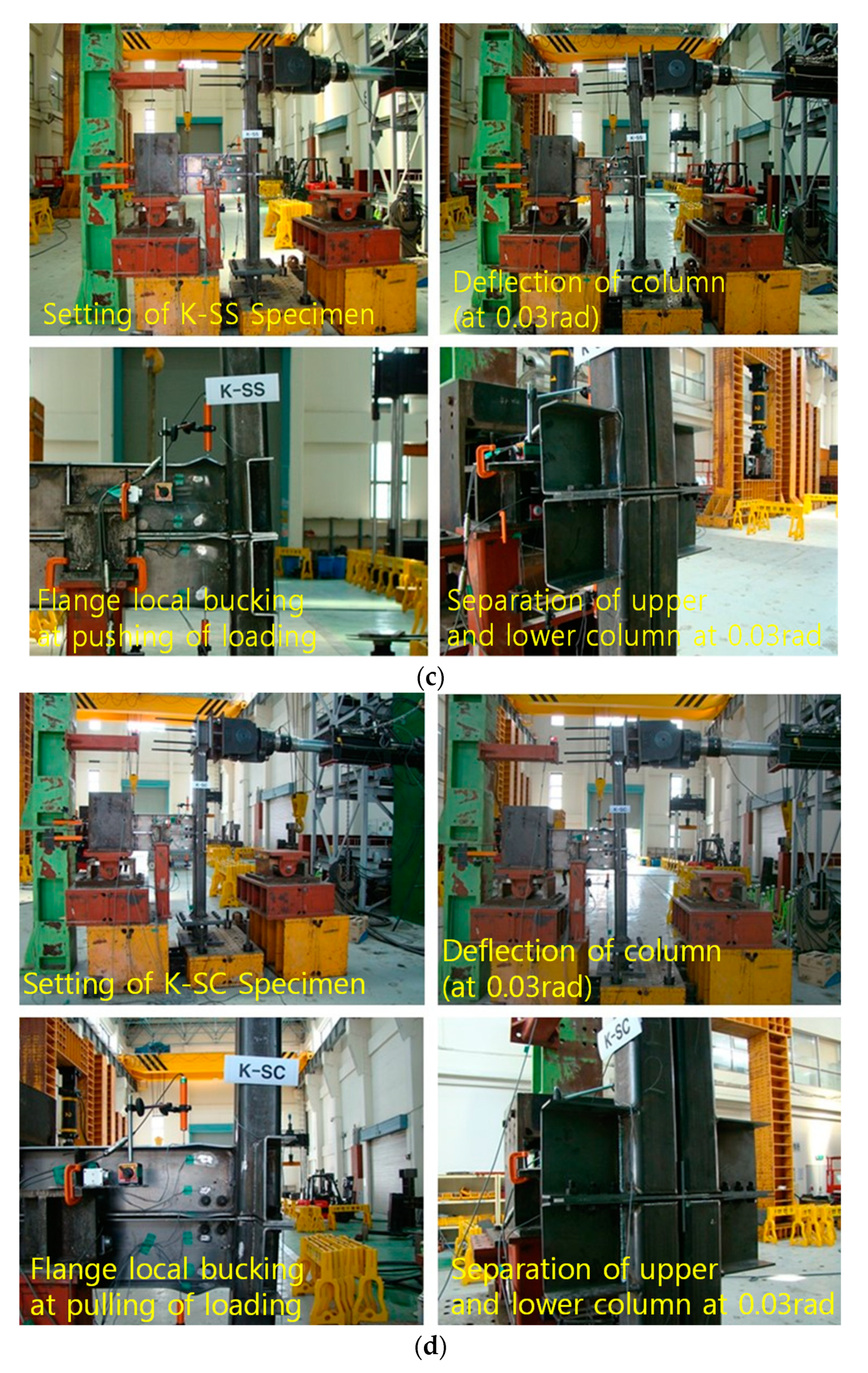
Although the K-LS and K-LC specimens were manufactured symmetrically, there was a gap between the left and right beams, which increased the torsion in the beam ends as the drift angle increased. This torsion was absent for the K-SS and K-SC specimens, as the gap for these test specimens was small. For all test specimens, formation of a plastic hinge on the beam flange was used to determine the maximum load.
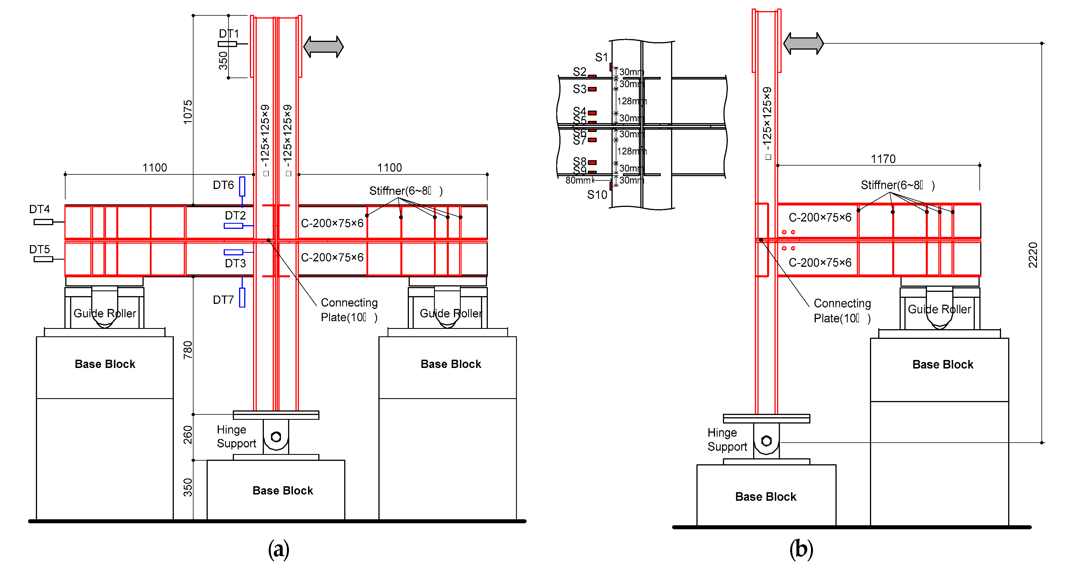
Table 3 shows the experimental results and
Figure 5 shows the key points in the test setup.
As shown in
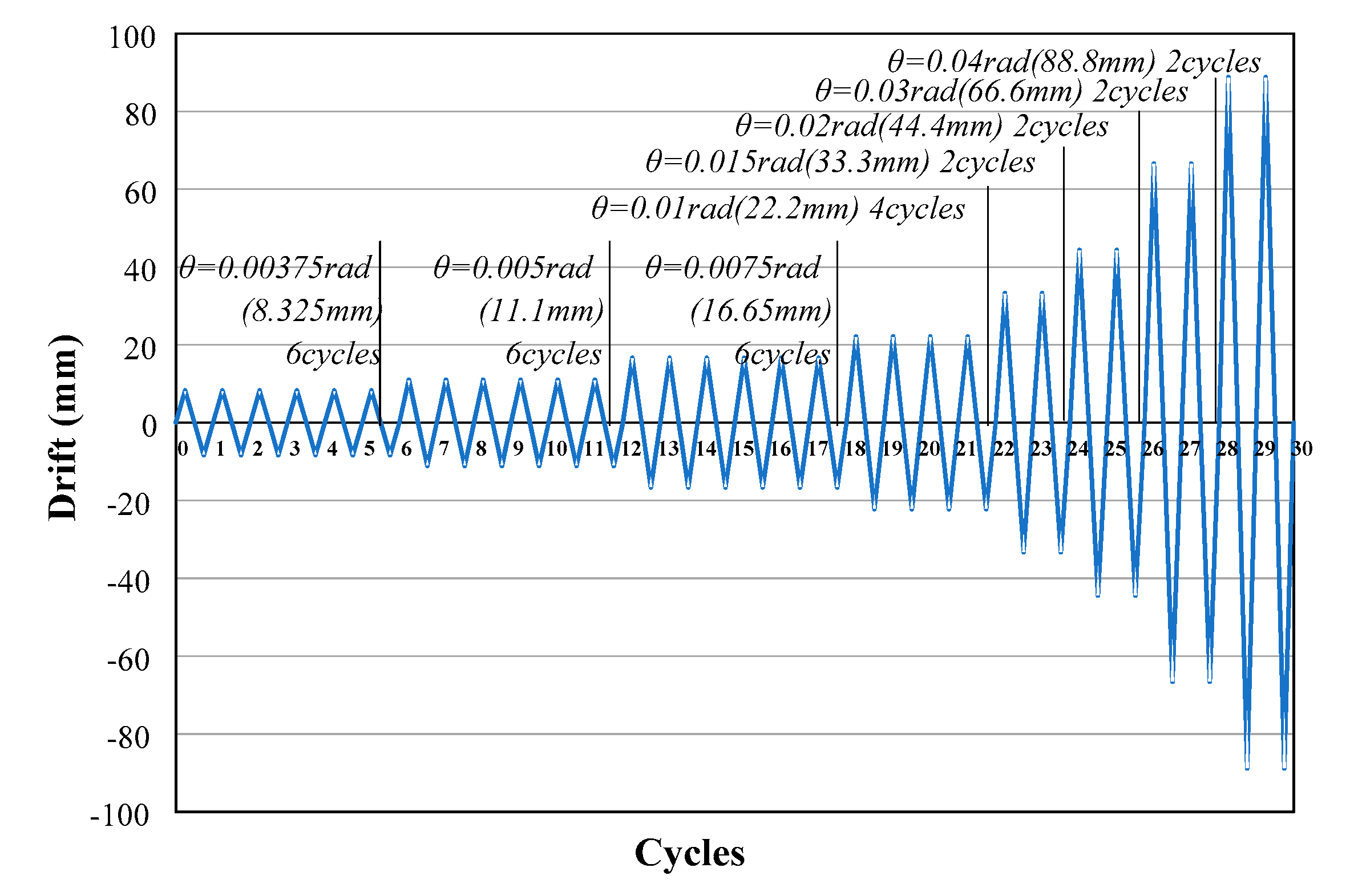
Figure 5a, for the K-LS specimen, excessive torsion occurred because a shim plate was not installed between the upper and lower beams of the roller end section. Thus, a loading schedule up to 0.03 rad was used for safety reasons. For the other test specimens, shim plates were installed, and the experiments were performed according to the loading schedule.
5.2. Comparison of Bending Moments
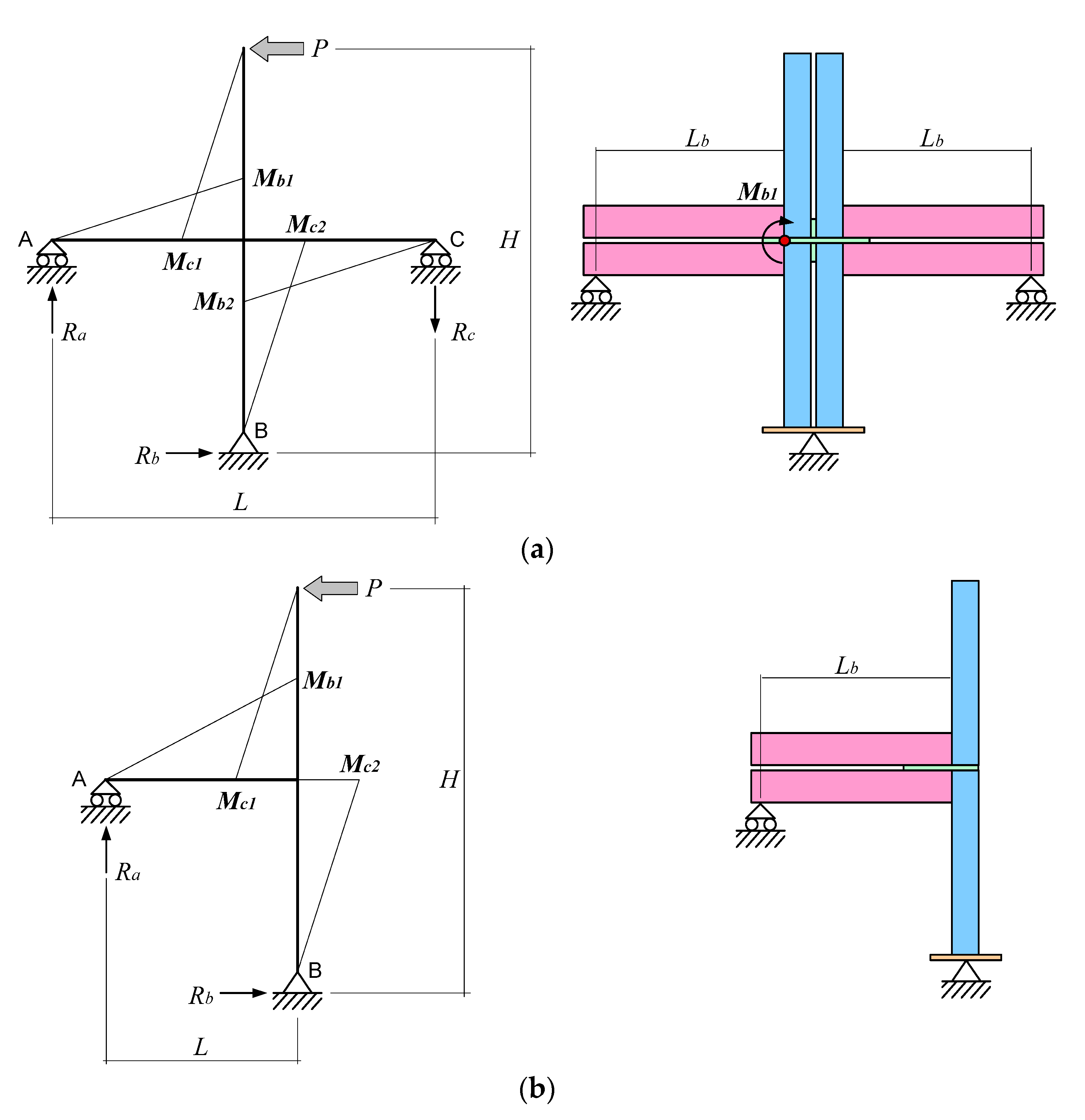
As the connection involves welding the column and beam, the bending moment applied in this area must be assessed first. As shown in
Figure 6a, the members of the cross-shaped test specimens were assumed to be line elements and the reaction force (
) in Equation (1) was first calculated on the basis of the force equilibrium; the bending moment (
) applied to the connection was calculated using Equation (2), and the distance between the roller end point of the beam and the connection area (
). The same calculation method can be used for the cantilever test specimen, as depicted in
Figure 6b.
The values thus obtained are the bending moments applied simultaneously to the upper and lower beams; these values may exceed the cumulative values of the plastic bending moment () for the beam cross-section due to the upper and lower beam composite effect. However, the test specimens used in this study were not connected in any way other than via the connector plates between the upper and lower beams, and thus it was reasonable to carry out the comparison assuming a value four times higher than the beam plastic bending moment. With an average yield strength of 263 N/mm2, obtained through the 200 × 75 × 6 mm channel beam material tests, the bending moment was calculated as 36.1 kN.m.
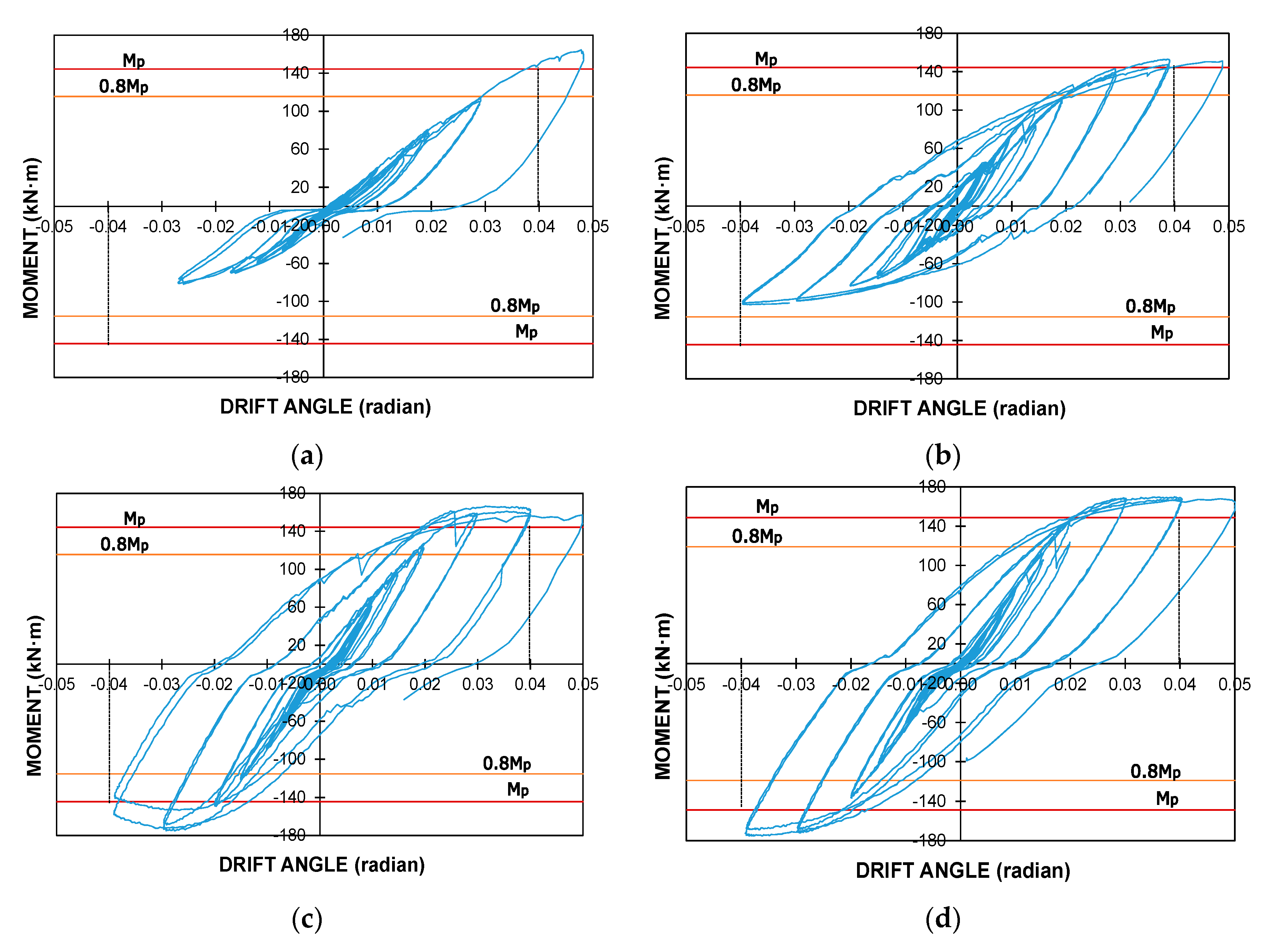
Figure 7 shows the relationship between the bending moment and story drift angle; the bending moment was obtained through substitution on the basis of the aforementioned method. The value four times higher than the beam plastic bending moment is also shown for analysis of connection performance based on the performance standard required for special moment frames. The K-LS specimen was compared to the K-LC specimen, taking into consideration the fact that cyclic loading was conducted only until 0.03 rad. These two test specimens were manufactured symmetrically, with no reinforcement to prevent torsion of the space between the left and right beams, resulting in an increase in the torsion effect; it was estimated that a plastic bending moment of 80% could not be maintained at a drift angle of 0.04 rad during the compressive loading interval (third quadrant).
On the other hand, the K-SS and K-SC specimens had relatively small spaces between beams that prevented torsion, maintaining a plastic bending moment of 80% at a drift angle of 0.04 rad during the compressive and tensile loading intervals (first quadrant). The K-LS and K-LC specimens differed in terms of whether a shim plate was installed between the upper and lower beams, as well as in the shape of their connector plates. The cross-shaped connector plate installed in the K-LC specimen was subject to compressive and tensile cyclic loading in the long edge direction of the horizontal plate, and thus the contribution of the vertical plate placed on the bending center line to the overall bending resistance was small. Thus, differences in behaviors until 0.03 rad can be considered to result from the presence of the shim plate. It was observed that installation of the shim plate increased the energy absorption capability or the hysteresis curve area.
Differences in behavior according to the shape of the connector plate in the K-SS and K-SC specimens were investigated. A significant difference in the maximum internal force between the first and second loading cycles of 0.04 rad for K-SS, which used a straight connector plate, was seen—stiffness degradation was observed after the maximum internal force was determined near 0.03 rad. By contrast, for the K-SC specimen, which used a cross-shaped connector plate, stiffness and the internal force were maintained, or showed a gradual increase at 0.04 rad, at the end of the cycle. In the case of loading in the horizontal direction (short edge of the connector plate), this behavior difference resulted from the ability of the vertical plate cross-section to sufficiently resist bending.
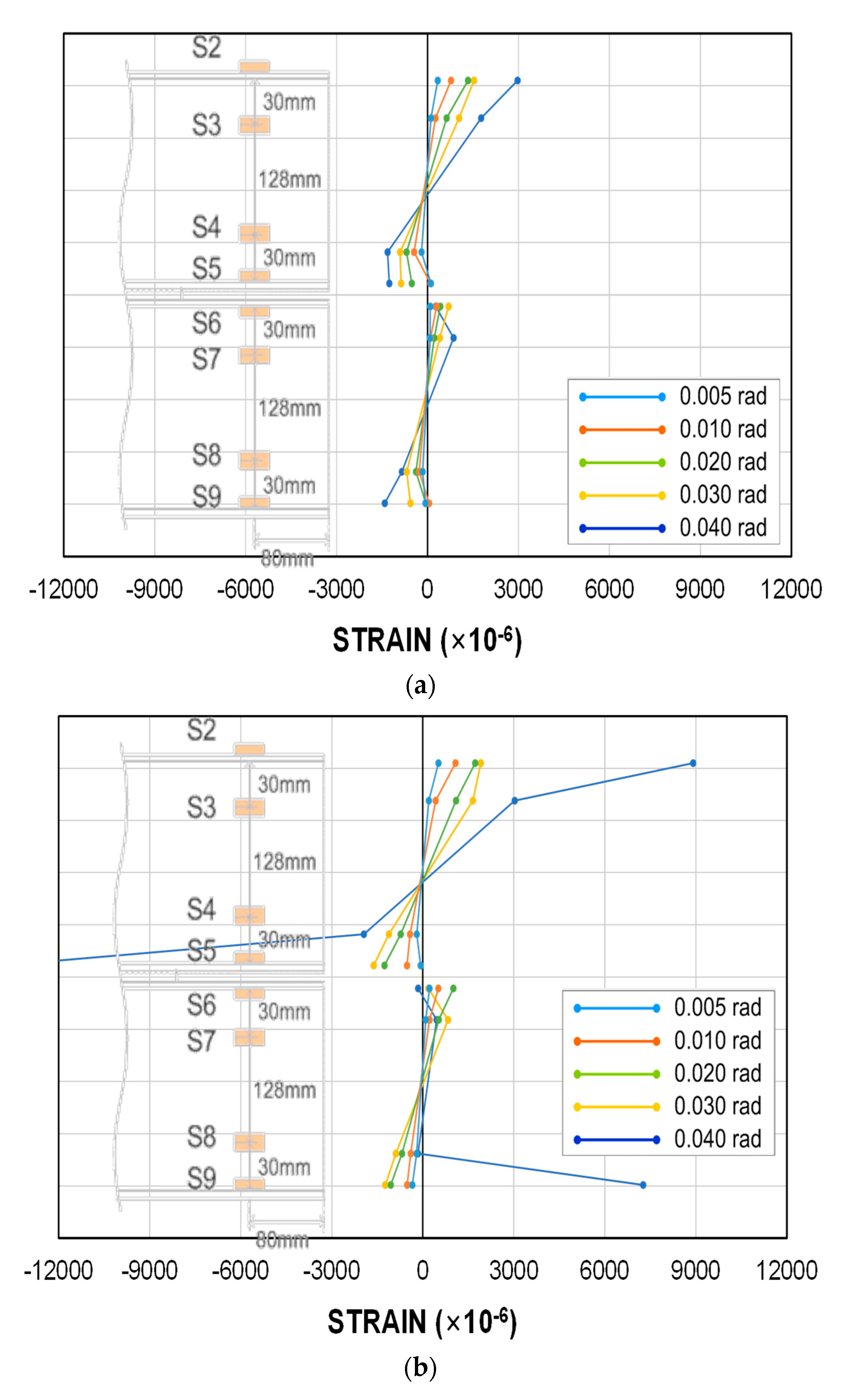
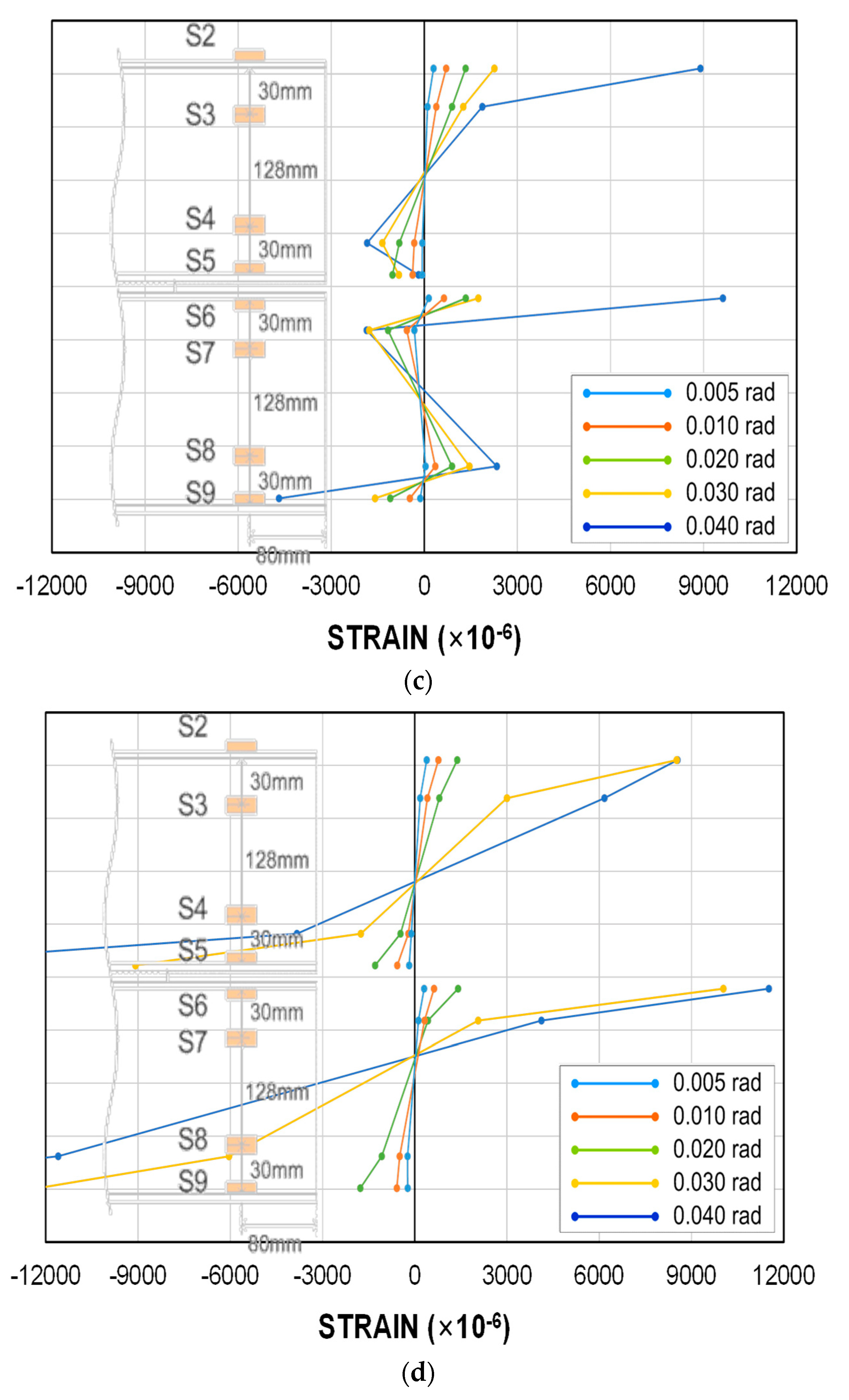
5.3. Strain Distribution Comparison
The strain values measured using eight strain gauges installed in the ceiling and floor beams are shown in
Figure 8 for each test specimen, for the first cycles of the loading schedule at the major drift angles (0.005, 0.01, 0.02, 0.03, 0.04 rad).
For all four test specimens, the ceiling and floor beams showed strain distributions similar to individual members, rather than composite behavior; reversal of strain distribution was observed due to local beam flange buckling or plastic hinge formation. The yield strain was calculated to be approximately 1300 μm (= 263/205,000) on the basis of the average yield strength (263 MPa) of the beam, obtained through material testing; it was observed that, for most test specimens, yielding of the ceiling and floor beams began at a drift angle of around 0.02 rad. Therefore, the ceiling and floor beams must be modeled as independent members in structural analyses; when modeled as a single member, the cumulative performance values of each cross-section must be considered.
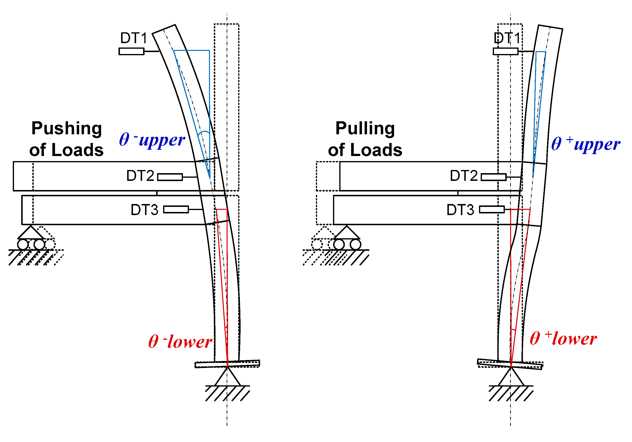
5.4. Column Drift Angle
To investigate the lateral column displacement difference according to the connector plate shape, we calculated the upper and lower story drift angles (
,
) for the compressive loading case (−) and tensile loading case (+), on the basis of the measurement values of the displacement gauge installed on the test specimens and the distance between the gauges, as shown in
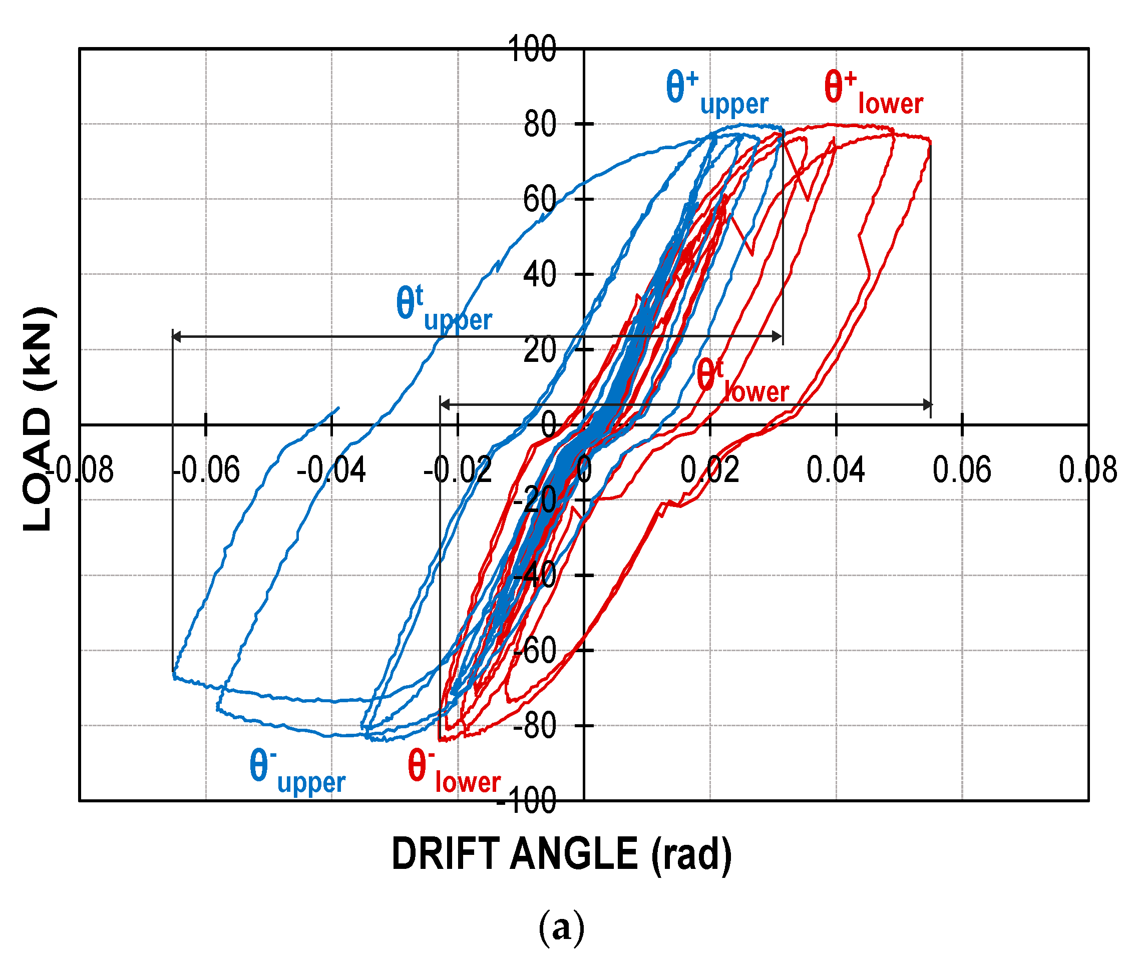
Figure 9. The calculated drift angles are shown in
Figure 10.
For the compressive loading case, an upward reaction force was generated on the roller end, increasing the deformation of the upper story column. For the tensile loading case, a reaction force in the opposite direction was generated such that the lower story column deformation increased.
The sum () of the drift angles (, ) due to the + and – loadings of the upper story column were calculated separately for the K-SS and K-SC specimens, under the assumption that changes in drift angle occur up to 0.04 rad in the loading schedule. In addition, the sums () of the drift angles (, ) were calculated according to the loading direction for the lower story column. The sums of the upper story and lower story column drift angles were 0.0968 rad and 0.078 rad, respectively, for the K-SS specimen, and the sums of the upper story and lower story column drift angles were 0.0934 rad and 0.080 rad, respectively, for the K-SC specimen.
The upper story column drift angle was 0.0034 rad greater for the straight connector plate than for the cross-shaped connector plate, while the lower story column drift angle was 0.002 rad smaller. Ultimately, the story drift angle increased by 0.0014 rad when a straight connector plate was used compared to a cross-shaped connector plate. If the story height is 3000 mm, the story drift increases by approximately 4 mm; the story drift of a 10-story structure thus reaches 40 mm, which can be an important factor for determining whether the usability criteria for lateral loads are satisfied.


