Article

Wear Behavior of Uncoated and Coated Tools in Milling Operations of AMPCO (Cu-Be) Alloy

by
Vitor F. C. Sousa
1,
João Castanheira
1,
Francisco J. G. Silva
1,2,*,
José S. Fecheira
1,
Gustavo Pinto
1,2 and
Andresa Baptista
1,2
1
ISEP—School of Engineering, Polytechnic of Porto, Rua Dr. António Bernardino de Almeida, 431, 4200-072 Porto, Portugal
2
INEGI—Instituto de Ciência e Inovação em Engenharia Mecânica e Engenharia Industrial, Rua Dr. Roberto Frias, 400, 4200-465 Porto, Portugal
*
Author to whom correspondence should be addressed.
Submission received: 30 June 2021 / Revised: 12 August 2021 / Accepted: 17 August 2021 / Published: 23 August 2021

Abstract

:
Copper-Beryllium alloys have excellent wear resistance and high mechanical properties, they also possess good electrical and thermal conductivity, making these alloys very popular in a wide variety of industries, such as aerospace, in the fabrication of tools for hazardous environments and to produce injection molds and mold inserts. However, there are some problems in the processing of these alloys, particularly when these are subject to machining processes, causing tools to deteriorate quite rapidly, due to material adhesion to the tool’s surface, caused by the material’s ductile nature. An assessment of tool-wear after machining Cu-Be alloy AMPCOLOY 83 using coated and uncoated tools was performed, offering a comparison of the machining performance and wear behavior of solid-carbide uncoated and DLC/CrN multilayered coated end-mills with the same geometry. Multiple machining tests were conducted, varying the values for feed and cutting length. In the initial tests, cutting force values were registered. The material’s surface roughness was also evaluated and the cutting tools’ edges were subsequently analyzed, identifying the main wear mechanisms and how these developed during machining. The coated tools exhibited a better performance for shorter cutting lengths, producing a lower degree of roughness on the surface on the machined material. The wear registered for these tools was less intense than that of uncoated tools, which suffered more adhesive and abrasive damage. However, it was observed that, for greater cutting lengths, the uncoated tool performed better in terms of surface roughness and sustained wear.

1. Introduction

Copper-Beryllium alloys have seen application in a great variety of industries, such as aeronautics and aerospace [1], molds, and other applications that are subject to hazardous conditions. These alloys are preferred over other copper alloys due to their good conductivity and strength [2], making them ideal for industrial mold applications, as their high thermal conductivity can reduce injection molding cycles by up to 80% [3]. However, these types of alloys have some processing problems due to their mechanical properties, such as high ductility, particularly for machining processes. There have been some studies about the processing of these alloys for injection mold applications, primarily directed at the electrical discharge machining of these copper-based alloys, as this process proves very useful in producing mold cavities [4]. This process is suitable for the machining of high-strength and high ductility alloys, as it does not cause any distortion during machining. However, this process is quite time-consuming as it has a very slow material removal rate and has high energy consumption [5,6]. Therefore, it would be quite useful to employ other types of processes in the production of molds and mold inserts, made from these copper-based alloys, especially copper-beryllium.
Machining processes are a viable option for the fabrication of these parts; however, there is little research conducted in this area, especially directed at machining optimization of these alloys and at the study of the wear behavior of tools applied in the machining of copper-beryllium and copper-based alloys. Understanding the wear behavior of cutting tools is quite beneficial as it provides information on the machinability of materials, and insights on what strategies to use, the best tool types, and even the most indicated tool coatings to machine a certain material [7,8]. By evaluating the wear mechanisms and machining performance of certain tools, providing knowledge on how wear is developed throughout the cutting process, the optimization of the machining process of a certain material becomes possible [9]; this is particularly useful when considering hard-to-machine materials, such as nickel-based alloys [10,11]. These studies offer insights on optimal machining parameters and the wear mode that tools undergo [12], enabling the selection of more adequate machining strategies, the development of new tools, or even application of the correct cooling method [13]. Studies such as these are also quite beneficial when it comes to choosing the right type of coating for a machining application, as they provide knowledge that is invaluable to produce new designs for tools and coatings [14]. Regarding machining optimization, there are a number of numerical and simulation methods that have proven useful in this regard; for example, using the Taguchi method to optimize certain machining parameters to obtain a better desired result, such as improving material removal rate [15], surface roughness [16,17], and even tool wear. These studies offer insight on the optimal machining parameters, even relating coating thickness and structure to the process’ outputs [18,19]. Other numerical methods rely on simulations, for example, the finite element analysis, offering predictions on the machining outputs and enabling further optimization, especially if paired with other optimization methods, such as the Taguchi method or grey relational analysis [20].
Tool coatings have proven to be quite an improvement in the machining process, especially in turning [21] and milling processes [22]; however, these can be applied to a wide variety of other metal-cutting processes, such as tapping, where the use of hard-coatings has provided a viable solution for tapping hard-to-machine materials by essentially improving tool life and cutting behavior [23,24]. These coatings directly impact the wear behavior and performance of cutting tools [25], lowering the produced surface roughness, sustaining wear, and even decreasing the cutting forces that are generated during the process [26,27]. One of these coating types that deserves some attention are diamond coatings used in machining as these significantly improve the wear behavior of cutting tools [28] and there have been some recent developments, further improving wear resistance by employing multilayered structures [29]. These directly improve the wear resistance of coatings, as the structure types confer the tool with properties such as improved thermal dissipation and improve crack propagation resistance, thus improving the overall tool’s life and performance [30]. Still, regarding the wear performance of coated tools, the influence of the tool’s substrate plays a significant role in the performance of a cutting tool. A poor substrate surface quality can produce defects during the deposition process that hinder the coated tool’s performance, promoting premature coating wear [31]. The tool’s substrate can also be improved, for example, by employing mechanical treatments before the deposition process [32]; these pretreatments are known to improve coating adhesion to a substrate, thus improving the wear behavior of the coating [33,34].
There have been quite a number of advances in the deposition processes used to obtain coatings, mainly PVD (physical vapor deposition) [35], with some novel techniques, such as HiPIMS (high-power impulse magnetron sputtering), producing strong coatings with high deposition rates. The correct selection of deposition techniques is also important, as some coatings are more useful for finishing operations, such as PVD coatings, while the CVD (chemical vapor deposition) coatings are used more for roughing operations due to the average thicknesses obtained by these deposition techniques, and the residual stresses that are present in the deposited coatings [21,22,36]. In the case of PVD coatings, the compressive residual stresses greatly increase the cutting edge’s strength, preventing premature wear and chipping, while still retaining properties that are best suitable for finishing operations [37,38]. Due to the increase in wear resistance conferred by deposited coatings, these can be applied to surfaces other than tools, such as injection molds. These coatings directly increase the lifespan of injection molds, particularly in conditions that are subject to severe wear [39] or even in the case of glass fiber reinforced plastic injection, as these fibers contribute to the premature wear of these injection molds [40]. Coatings are also applied as means to improve the corrosion resistance of molds and mold inserts, as seen in the study by Mindivan [41], where a coating of WC/C was applied to a copper-beryllium alloy used in the fabrication of injection molds. The author evaluated the corrosion and tribocorrosion behavior of the coating, comparing it to an uncoated sample of copper-beryllium alloy. It was found that the corrosion resistance of the coated substrate was higher than that of the uncoated one. It was also revealed that the wear resistance was also improved. This was not only due to the high hardness of the coating, but also the surface morphology of the coated surface, which showed a smooth and polished appearance, thus improving the tribocorrosion behavior.
Regarding the machining of copper-beryllium alloys, there have been some recently performed studies conducted on this matter, with some interesting findings being reported, for example, in the study by Sharma et al. [42], where the authors investigated tool and hard particle interactions in nanoscale cutting of copper-beryllium. It was concluded that the crystallographic planes of the base material heavily influence the generated cutting forces, material deformation, and the tool’s condition, offering insight on the cutting behavior of this material and its machinability. The same authors conducted a similar study [43], studying tool wear mechanisms sustained during turning of the same copper-beryllium alloy, using a diamond turning tool. The authors found that the main wear mechanism experienced by the tool was amorphization of the diamond structure while machining the alloy. The high temperature generated in the tool–material interface, as seen in a previous study [42], and the interaction between hard particles of the alloy and the tool, caused vibrations during machining, which negatively impacted tool wear, and significantly increased the surface roughness of the machined material. The authors also conducted turning operations on pure copper, obtaining a significantly longer (60%) tool life. There have also been some studies carried out regarding the optimization of the machining process of these alloys, as in the study by Devi et al. [44], where the optimal machining parameters for turning beryllium-copper alloy using a CBN and HSS tools were determined. The authors used the response surface methodology to design the experiments, then conducted an analysis of variance to optimize the process. The authors successfully determined the optimal values for cutting speed, feed rate, and depth of cut, to produce the best values regarding material removal rate and surface roughness. Another similar study, performed by Alagarsamy et al. [45], also analyzed the influence of machining parameters in the material removal rate and produced surface roughness. Here, the authors considered three machining parameters, cutting speed, feed rate, and depth of cut. They used grey relational analysis and an analysis of variance to determine the most influential turning parameter in the mentioned outputs, concluding that the cutting speed was the most influential parameter, followed by the depth of cut and feed rate. The authors then performed experimental studies to validate this, determining in the end the optimal machining parameters to obtain the highest value of material removal rate. There have also been some studies conducted on the optimization of end-milling operations of copper-based alloys, such as those by Monel [46,47]. Shihan et al. [48,49] evaluated the influence of machining parameters on process sustainability and stability, effectively determining the optimal machining parameters to obtain the least amount of energy consumption and vibrations that are developed during machining. It was found that the most influential parameter on both factors is spindle speed, being followed by feed rate. Regarding the analysis of the wear mechanisms that were developed during the milling of copper-beryllium alloys, although research in this matter is quite sparse, Zuo et al. [48,49] conducted some studies in this regard, testing different cutting speeds and evaluating the influence of this parameter on the wear behavior of uncoated and TiAlN-coated tools. The authors found that the main wear mechanism that is developed is adhesive wear, which is responsible for most of the flank wear registered in the tools. Furthermore, this adhesive wear promotes abrasion, further decreasing the tools’ life and negatively impacting the produced surface roughness. The authors also reported the formation of an adhesive layer of material on the tool’s surface, directly correlated with the wear registered on the flank’s surface. It was also registered that the cutting temperature developed during machining greatly promoted adhesive wear on the tool’s surface, causing notch wear and chipping of the tool [48].
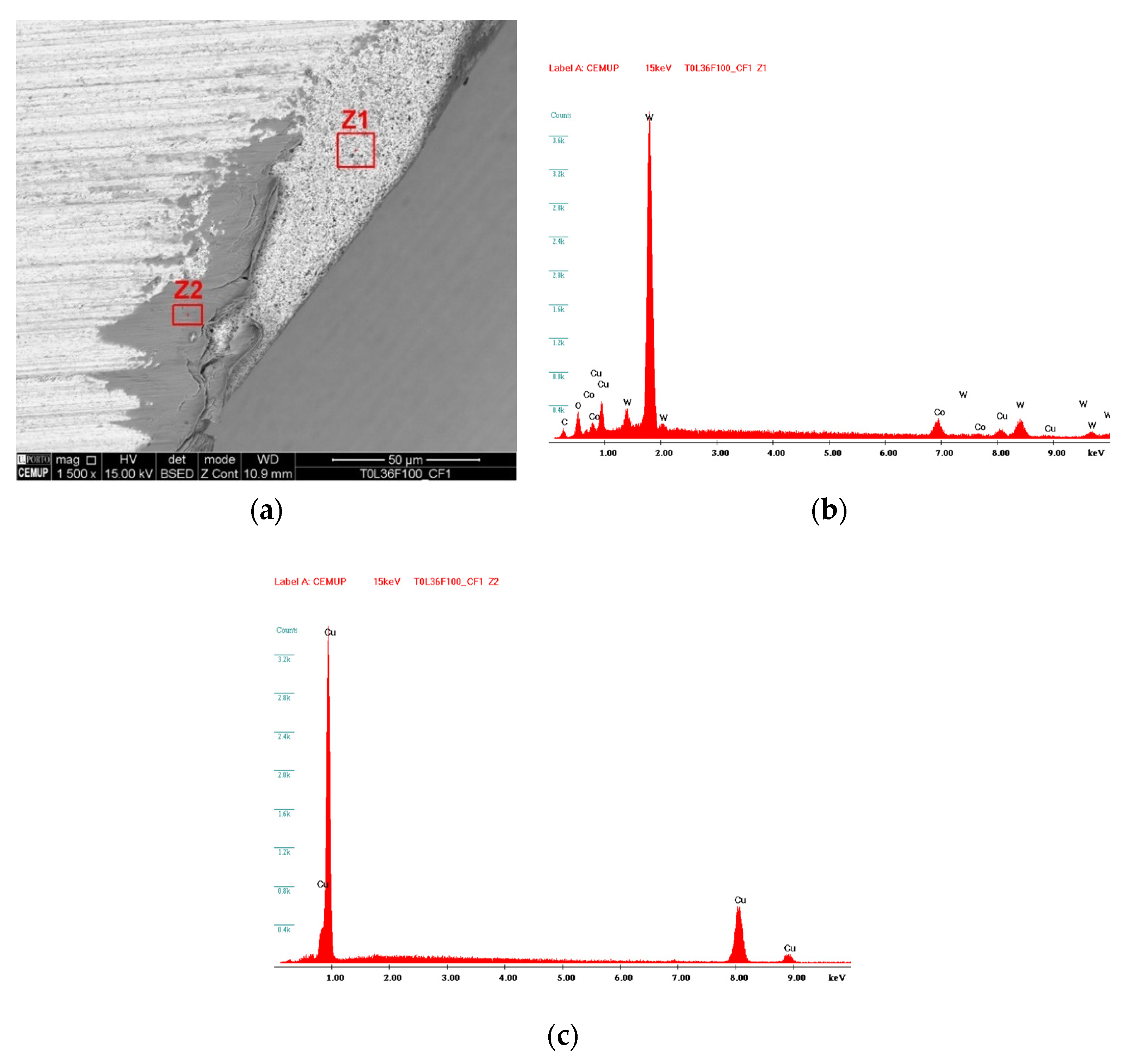
Studies such as the ones presented in the previous paragraph provide valuable information that can be used to optimize the machining of copper-beryllium alloys, as this is still a subject that is not widely explored. Moreover, there is a clear gap in the literature about the study of the wear mechanisms involved in the machining of copper-beryllium alloys and coated tools in general. In the present paper, a comparison of uncoated and multilayered DLC (diamond-like carbon)/CrN coatings in the machining of copper-beryllium alloy is made, providing an analysis of the produced surface roughness and tool wear behavior, relating the flank wear and the wear mechanisms sustained by these tools with the produced machining quality.

2. Materials and Methods

Given the variety of materials, tests, and equipment used in this study, this section is divided into two main sections, namely materials and methods. In this way, within each section there are still subdivisions that allow for the transmission of complementary and organized information from the different steps of this work.

2.1. Materials

2.1.1. Workpiece Material

To perform this study, an AMPCOLOY® 83 copper-beryllium (Cu-Be) alloy was chosen as the material to be machined due to the reasons previously pointed out. The choice of this copper-beryllium alloy is related to the fact that it is not explored in depth in terms of research, together with its high importance in the plastic injection molding industry for the manufacture of components for molds, such as inserts in molding zones.
The material was supplied in a block, with dimensions of 103 × 153 × 153 mm3 and 21.4 kg, by Ampco Metal Portugal, Lda. (Porto, Portugal). The combination of its properties allows the material to be an excellent thermal and electrical conductor, and, at the same time, offer good machinability. Its chemical composition and mechanical properties, provided by the manufacturer, can be seen in Table 1 and Table 2.
As this alloy contains 1.9% beryllium, it is recommended that precautions should be taken to avoid inhalation or contact with eyes and skin for any operation that produces dust or fumes. Generally, it poses no risk during conventional machining processes (turning or milling).

2.1.2. Tool Substrate and Coating

The cutting tools used in machining tests were made of a sintered substrate of tungsten carbide (WC-Co), grade 6110, with about 0.3 µm grain size and a binder of 6% Co (wt.), supplied by InovaTools, SA (Leiria, Portugal). Regarding its dimensions, it is a toric tool of 4 mm in diameter with a 0.5 mm tip radius, and a total length of 57 mm. Its shank was 6 mm to make the tool more robust and reduce vibrations from the cutting process as much as possible. The tools had three cutting knives. The criteria for its selection fell on the fact that it is the ideal number of knives for machining soft materials, and, at the same time, they provide better surface finishes on the machined part.
In the study, only this type of cutting tool was used. The main difference between these tools was the inclusion of a coating. Therefore, the main objective was to carry out a comparison of wear mechanisms between coated and uncoated tools, to verify which tool is more suitable for machining copper-beryllium alloy.
Regarding the coating, it was selected based on the material to be machined. Therefore, and since the material tends to adhere to the cutting tool, a coating that works as a self-lubricating agent was chosen. The selected coating presented a multilayer structure, with chromium nitride (CrN) sublayers and a diamond-like carbon (DLC) top layer. For its application to the tools, a CemeCom CC800/9ML PVD Unbalanced Magnetron Sputtering tool (CemeCon AG, Aachen, Germany) was used.
To carry out the coating deposition, it was necessary to clean the sample with acetone in an ultrasonic bath for 15 min. After completion, the acetone was changed, and a new ultrasonic bath was performed again for 5 min to complete the cleaning process.
After the tool-cleaning process, they were mounted on a proper support, where only the shank was not exposed to the coating deposition process. In order to make the surface coating of the tools as homogeneous as possible, they were mounted on a support with a rotating base in the deposition chamber, which rotated at 1 rpm during the deposition time. The parameters used in the tools’ coating deposition can be seen in Table 3.

2.2. Methods

2.2.1. Tools and Coatings Evaluation

To evaluate and measure the coating thickness of the cutting tools using scanning electron microscopy (SEM), a coated sample was cut with the aid of a STRUERS MINITOM (Struers, Inc., Cleveland, OH, USA) disc saw, equipped with a thin disc with an electroplated coating incorporating diamond particles. At the end of the cutting process, the sample was incorporated into thermosetting resin and placed in a hot press in a STRUERS PEDOPRESS (Struers, Inc., Cleveland, OH, USA). This process allowed to obtain better conditions for the subsequent process of handling the samples that was required in the process of sanding and polishing the cross section. Since the external coating of the tool was mainly composed of carbon and knowing that the resin used is also composed of carbon, some problems in the correct visualization of the coating through SEM could be found. To ensure a perfect analysis, and if alternative analysis was needed, an additional tool was prepared. To this end, the tool was incompletely cut (about 90% of its diameter), and fragile fracture (after cryogenic bath for 45 min) was carried out to expose the coating layers.
In the sanding operation, sandpapers of decreasing grain size were used, proceeding in the following sequence: 220, 500, 800, and 1200 grit. After the sanding process, the samples were rotated 90°, improving the reduction of the grooves left on the surface by the previous sandpaper. To eliminate the grooves, the samples were first polished using a diamond slurry of 3-µm diamond grain size, followed by polishing using a 1-μm diamond slurry, for approximately 5 min each time.

2.2.2. Coating Thickness Analysis

For the analysis of the thickness of the coating of the cutting tools, the procedure described above was used. The measurement of the coating thickness was performed with the aid of an FEI Quanta 400 FEG (Field Electron and Ion Company, FEI, Hillboro, OR, USA) scanning electron microscope, supplied with an EDAX Genesys (Edax Ametak, Mahwah, NJ, USA) energy dispersive X-ray spectroscopy microanalysis system.
The same magnification range was used for all images obtained by SEM to analyze the composition of the coating, allowing for greater ease in analyzing and comparing the obtained results. A beam accelerating voltage of 15 kV and backscattered electron detector (BSED) were used. EDS spectra were taken to confirm the chemical composition of the coating and draw the necessary conclusions. For the acquisition of EDS spectra, a beam acceleration voltage of 10 kV was used, since, within this range, it is possible to obtain all the elements that make up the coating.

2.2.3. Machining Tests

Machining tests were performed with the aid of a HAAS VF-2 CNC machining center (HAAS Automation, Oxnard, CA, USA), capable of reaching a maximum speed of 10,000 rpm. The cutting tool was fixed to the machine shaft using an ISO40 DIN69871 collet holder, an ER32 DIN6499 collet and an ISO 7388-2 tie rod. For fixing the material block to the machine table, a machining press vise with a maximum opening of 200 mm was used. The machining strategy used in the tests was carried out to guarantee greater cutting distances, i.e., to take advantage of the smallest number of passes with a greater cutting distance of the tool.
The machining also was used with the inclusion of a lubricant/coolant in the contact area of the tool with the material, using a cutting lubricant, which was composed of 5% soluble oil in 95% water.
The different parameters recommended by the manufacturer and used in the machining tests can be seen in Table 4. Tool labeling was organized to facilitate their identification. Therefore, TxLyFz is the identification of the tools’ reference. To identify the coated from the uncoated tools, the letter x is assigned a value, where 0 represents uncoated and 1 represents coated. Regarding the cut length, it is represented by the letter L and can take the value of 18, 36 and 48, which represent the length in meters of the cut performed by the tool. Finally, the letter F represents the feed rate, which can be taken as values of 350, 750, or 1500 mm/min.
The axial cutting depth used was 0.5 mm and the radial cutting depth was 2.5 mm. The cutting speed remained unchanged at 126 m/min, with the feed rate and cutting length being varied, to verify its influence on the wear mechanisms of the tools.
The tool entered perpendicularly and outside the edge of the material, carrying out a linear program of facing along its largest face, with an exit extension of 2 mm.
The first tests were carried out on three uncoated tools, using a feed rate of 750 mm/min and cutting lengths of 18 m, 36 m, and 48 m, in the first, second, and third tests, respectively. Between each test interval, analysis of surface roughness was performed, a procedure that will be described later in this section. Then, tests were carried out on three more uncoated tools, using a feed speed of 1500 mm/min and a cutting length of 18 m, 36 m, and 48 m, in the first, second, and third tests, respectively. Likewise, the results of surface roughness were taken between intervals of each test. All tests were replicated three times to dispel possible reading errors or unexpected phenomena.
The same procedure was repeated for the tests for the uncoated tools, to verify and compare the wear mechanisms on cutting tools, to reach a conclusion about the best tool for machining AMPCOLOY® 83. These tests allow to verify the evolution of the wear of the cutting tools at different feed rates, also allowing to relate the cut length with the value of the surface roughness on the machined part of the surface. Note that three tools were tested for each test condition to extract the average results of the values under analysis.
At the end of each test, the tools were properly prepared (subjected to cleaning in an ultrasonic bath with acetone for 5 min) and packed in a suitable box. The tools were later analyzed by SEM, making it possible to analyze and measure the wear mechanisms suffered during the cutting process, as well as characterize their coating, if they had one.

2.2.4. Cutting Forces Analysis

To analyze the cutting forces developed in the milling of AMPCOLOY® 83, a KISTLER 9171A dynamometer (Kistler, Winterthur, Switzerland) was used, coupled to a KISTLER 5697A1 data acquisition system. This equipment allowed the recording of the cutting forces developed in the X, Y, and Z axes, as well as the developed moment (Mz).
The equipment was attached to a CNC machining center spindle and the tool was fastened to the equipment. The acquisition of cutting forces data were selected based on the rotation speed of the spindle, allowing to record the forces generated on the cutting edges of the tool for each rotation. Preliminary tests were carried out analyzing the cutting forces, verifying that these were very low. It was also possible to conclude that the variation in the cutting forces was minimal throughout the stipulated period of the cut. Therefore, the tests of the cutting forces were not considered, as these have no influence on the level of wear of the tools, in the specific case of milling this type of alloy. Moreover, the main objective of measuring these forces was to identify a significant variation in the cutting forces with the increase in wear, which was not possible due to the smooth variation of the forces in all axes.

2.2.5. Surface Roughness Analysis

The evaluation of the roughness of the machined surface is considered a very important factor since the requirements for precision and operation are very demanding. A Mahr Perthometer M1 profilometer (Mahr, Gottingen, Germany) was used to analyze the surface of the machined part after machining tests. This equipment was used to determine the most common surface roughness parameters according to DIN EN ISO/AMSE/prEN 10049; arithmetic mean roughness (Ra), mean roughness depth (Rz), and maximum roughness (Rmax). Each test was performed with a cut-off of 0.8 mm, and a measurement length of 5.6 mm, which corresponded to seven cut-offs, with the first and last segment of 0.8 mm being eliminated due to errors that may result from the probe’s acceleration and deceleration at the time of measurement.

2.2.6. Tools Wear Analysis

After the machining tests and tool preparation, they were submitted for SEM analysis. In this way, it was possible to identify and quantify the level of wear on the cutting tools used in the tests. For this analysis, and as mentioned above, an FEI Quanta 400 FEG tool was used.
For cutting tool analysis, it was necessary to create labels, as shown in Figure 1, where each cutting knife is identified with a number. Figure 1b represents the analysis of the cutting knife’s number 1 rake face. This labeling allows an easy analysis and identification of the cutting knife under study. Throughout the study, it was necessary to create labels in order to simplify the nomenclature of the samples. Therefore, RF stands for rake face and CF stands for clearance face.
The flank wear (VB) measurements of the cutting tools were carried out according to ISO 8688-2:1989. The results will be presented in the next section.

3. Results and Discussion

In this section, the results from the machining tests are presented; these will be divided into different sections.

3.1. Coating Tools’ Characterization

To characterize the tools’ coatings, samples were prepared according to the procedure described in the previous section. The samples were then subjected to SEM analysis. The coating structure was analyzed using SEM, as well as its chemical composition via carrying out EDS analyses. It was determined that the coating had a multilayered structure, composed of CrN and DLC layers, as can be observed in Figure 2a. The thickness of the layers was also determined, by performing different measurements in different places of the sample. An example of the measurements performed can be observed in Figure 2b.
As can be observed in Figure 2a, the coating is composed of four layers, each of these was subjected to EDS analyses and their chemical compositions were determined. The spectra obtained from these can be observed in Figure 3.
In Table 5, the average coating thickness for each layer (identified by zone, according to Figure 2a) and their respective compositions are presented.
The coating is composed of alternating layers of CrN and DLC (as previously mentioned), with the first deposited layer being composed of CrN. This multilayered structure improved the crack propagation resistance of the coating. Furthermore, the outer layer was a DLC coating, acting as a solid lubricant, enabling for lower friction generated during machining.

3.2. Surface Roughness Analysis

In this section the results obtained from the surface roughness analysis of the machined part are presented. The surface roughness assessment method has been described in a previous section. In Table 6, the mean values of Ra are presented.
These values are presented as surface graphs in Figure 4 and Figure 5, to evaluate the surface roughness value variation regarding the machining test conditions.
As seen from the figures and table presented above, the values of the surface roughness tend to rise for higher values of feed rate and cutting length. For the condition of 1500 mm/min, the surface roughness values were the highest for both tools. Although the behavior of the surface roughness values was the same for both coated and uncoated tools, the lowest values of surface roughness were detected for the coated tools for cutting lengths up to 36 m. However, for the maximum cutting length conditions (48 m), the uncoated tools produced a better surface finish on the machined material when compared to the coated tool. A bar graph comparing the surface roughness of both of these tools for each of the tested conditions can be observed in Figure 6.

Preliminary Study of the Surface Roughness at a Lower Feed Rate Value

Trying to analyze the influence of feed rate on the produced machined surface quality, some additional tests were conducted. These tests were performed at a 350 mm/min feed rate and with a 48 m cutting length. Three tests were conducted for each tool, uncoated and coated, analyzing the behavior of the machined surface roughness from the beginning of the test until it reached a cutting length of 48 m. In Figure 7, the evolution of surface roughness for both coated and uncoated tools can be observed.
As can be observed from Figure 7, the coated tool causes a higher level of surface roughness; however, the overall values of surface roughness obtained using this feed rate value are very satisfactory, for both the uncoated and coated tools, with these producing a surface finish quality good enough to enable the skipping of a manual polishing operation after machining. However, this could be explored in a more detailed manner by analyzing the wear mechanisms of both tools for each of the cutting length stages.

3.3. Wear Analysis

Each of the tested tools were subjected to SEM analyses, to evaluate the wear. The flank wear of the tools (VB) was also assessed, and the values obtained are presented later in this section.
The influence of the feed rate and cutting length in the tools was studied, offering a comparison between the coated and uncoated tools. In Figure 8, Figure 9 and Figure 10, the wear of the tools tested at 750 mm/min and 1500 mm/min feed rate, and 18 m, 36 m, and 48 m cutting lengths can be observed.
By observing Figure 8, Figure 9 and Figure 10, it is possible to conclude that increasing the feed rate to 1500 mm/min induces a significant increase in tool wear, for both coated and uncoated tools. However, there is a difference in wear behavior for both these tool types: for the coated tools tested at a feed rate of 750 mm/min, a premature wear of the coating can be found out at a cutting length of 18 m. With the increase in cutting length, the amount of wear sustained by the tools also increased significantly. This increase in wear was observed in uncoated tools; however, in a lesser degree, it was particularly found for higher cutting length values.

3.3.1. Flank Wear Measurements

The mean values of VB were measured for each of the tested tools, as was done with the surface roughness values. These values are presented as surface graphs, as seen in Figure 11 and Figure 12.
As seen in Figure 11, the flank wear that is sustained by uncoated tools is lower for the 18-m cutting length cutting conditions, with the wear rising with an increase in this parameter. Additionally, a wear increase is also registered for higher feed rate values. The wear that these tools sustain influence the machined surface roughness, with this value increasing for higher wear values.
Similar to what was registered for the uncoated tools, the minimum values of flank wear were obtained for lower cutting lengths and feed rate values. Additionally, as was registered in the surface roughness analysis, the coated tools suffered less wear than the uncoated ones for cutting lengths of up to 36 m, for both the feed rate values of 750 mm/min and 1500 mm/min. This comparison can be observed in the form of a bar graph in Figure 13.

3.3.2. Tool Wear Mechanisms Analysis

In this section, the identified wear mechanisms are presented. These were determined by performing SEM analyses for each of the tested tools. The main wear mechanism that was registered was adhesive wear, registering a built-up-edge, which was expected as the machined material is quite ductile.
In Figure 14a, it is possible to identify the adhesive wear on an uncoated tool, with adhered material being registered on the tools’ cutting edge. Chipping of the substrate is also registered. EDS analyses were carried out to determine the presence of adhered material, as seen in Figure 14b,c.
The coated tools were also subject to adhesive damage, as can be observed in Figure 14, in the Z4 area. In addition to the wear mechanism registered in the uncoated tools, these tool types suffered coating delamination, caused primarily by the adhesion of material to the tools’ surface. Figure 15 shows that the tool suffered substrate exposure, as well as outer layer delamination, as seen in Z2, which corresponds to the intermediate CrN layer. EDS analysis carried out on this tool can be observed in Figure 16.
In all the analyzed coated tools, delamination and erosion of the first DLC layer was registered, with this first layer being peeled off in the early stages of the machining tests (for cutting lengths of 18 m).
Figure 17a,b presents the main wear mechanisms registered in the uncoated tools; more specifically, for uncoated tools tested at a cutting length of 48 m and feed rate values of 750 mm/min and 1500 mm/min. Once again, the presence of adhered material was found, that was deposited in the craters caused by machining. It can be observed that, for higher feed rate values, adhesive wear was more severe. In Figure 17b, it can be observed that the material adheres to the top of the tool, compromising the machined surface quality. Furthermore, the substrate suffers considerably more damage for higher feed rates, with the cutting edge breaking and chipping being registered.
In Figure 18, a comparison of the wear mechanisms sustained by coated tools tested at a cutting length of 48 m for both feed rate values is shown. The main wear mechanisms that these coated tools suffered were coating delamination, adhesion, and tool chipping, for both feed rate conditions. However, for higher feed rate values, considerably more chipping damage to the tool was registered, as seen in Figure 18b, which negatively impacting the machined surface roughness. For lower feed rate values, the main mechanisms were adhesion, coating delamination, and chipping of the cutting edge.
A discussion of these results cannot be performed due to the absence of results reported for these kinds of alloys.

4. Conclusions

In this study, a comparison of uncoated and CrN/DLC multilayered coated tool performance in the machining of a copper-beryllium alloy was made. Various machining tests were performed, evaluating the influence of both cutting length and feed rate on the tools’ wear behavior and produced machined quality. The following conclusions can be drawn:
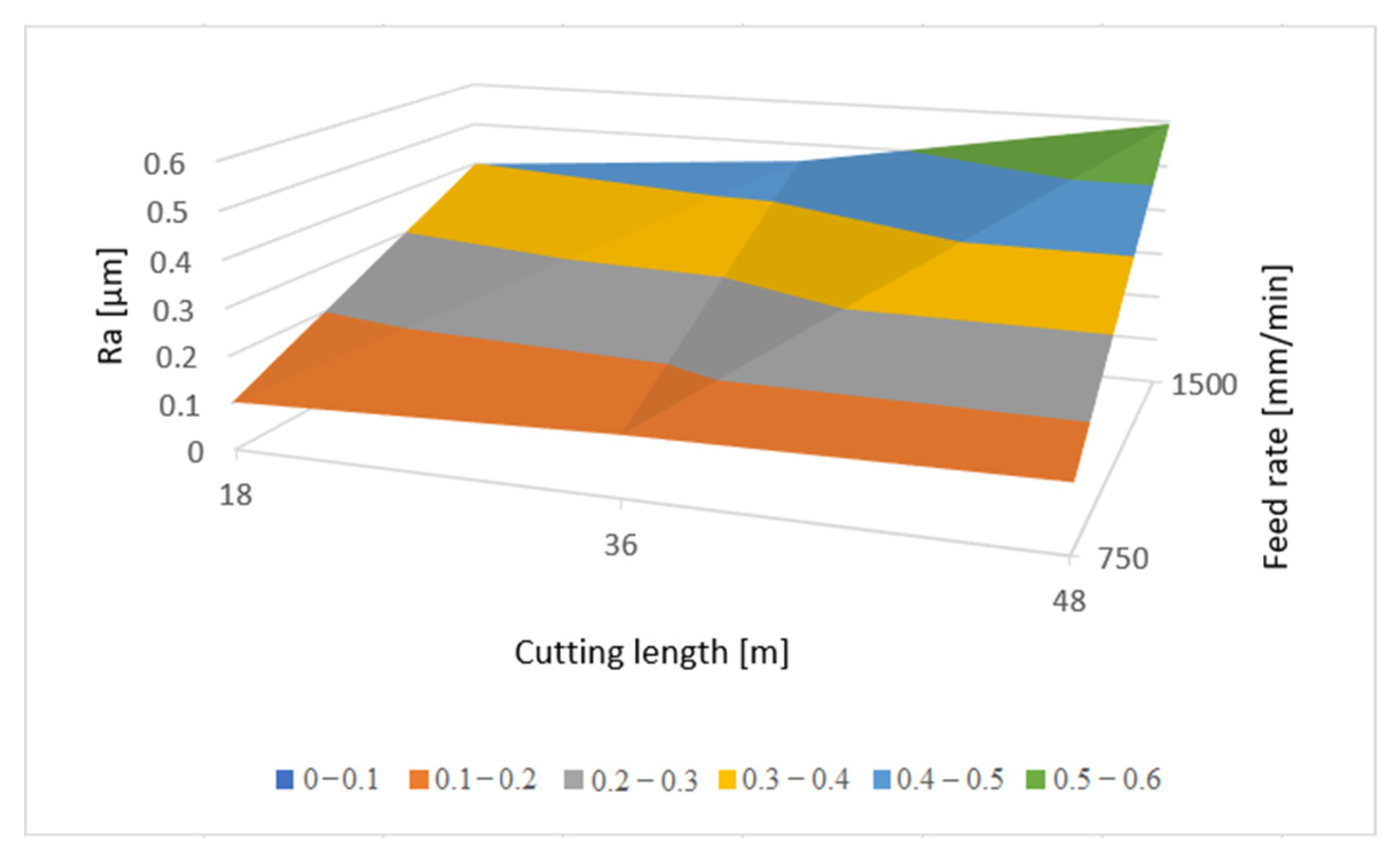
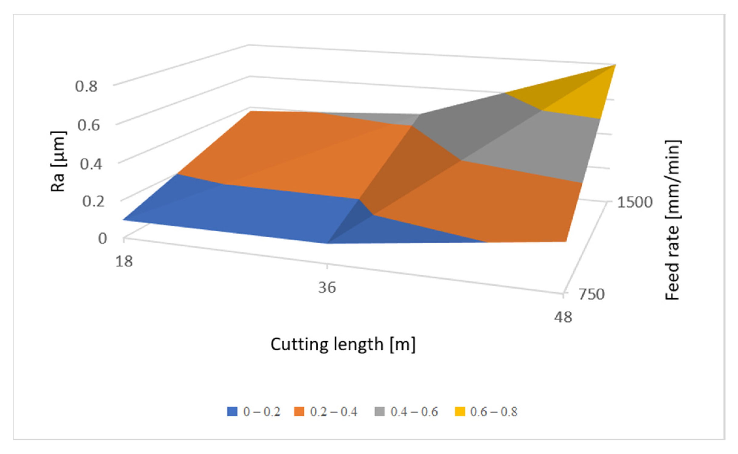
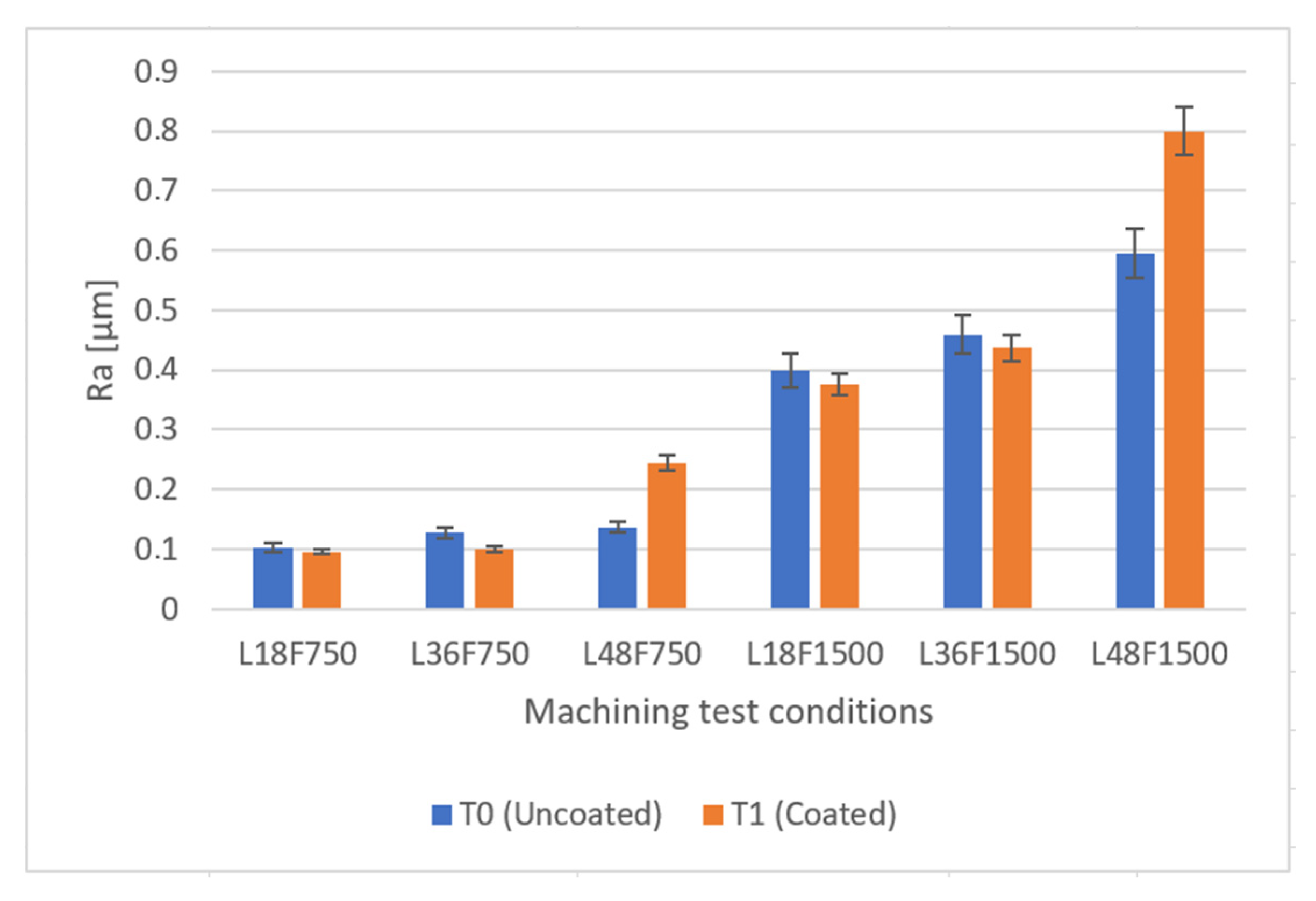
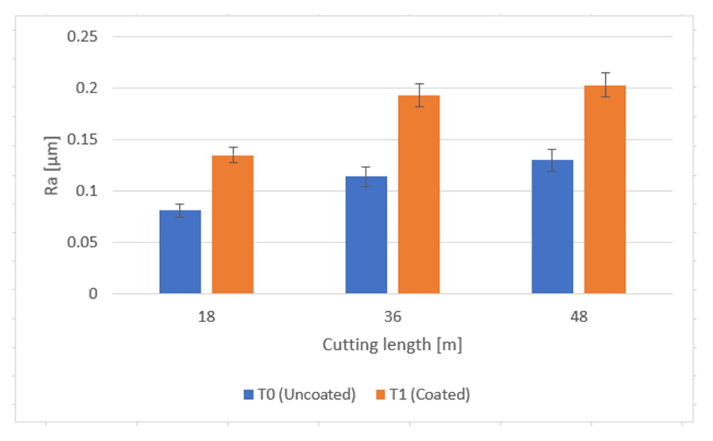
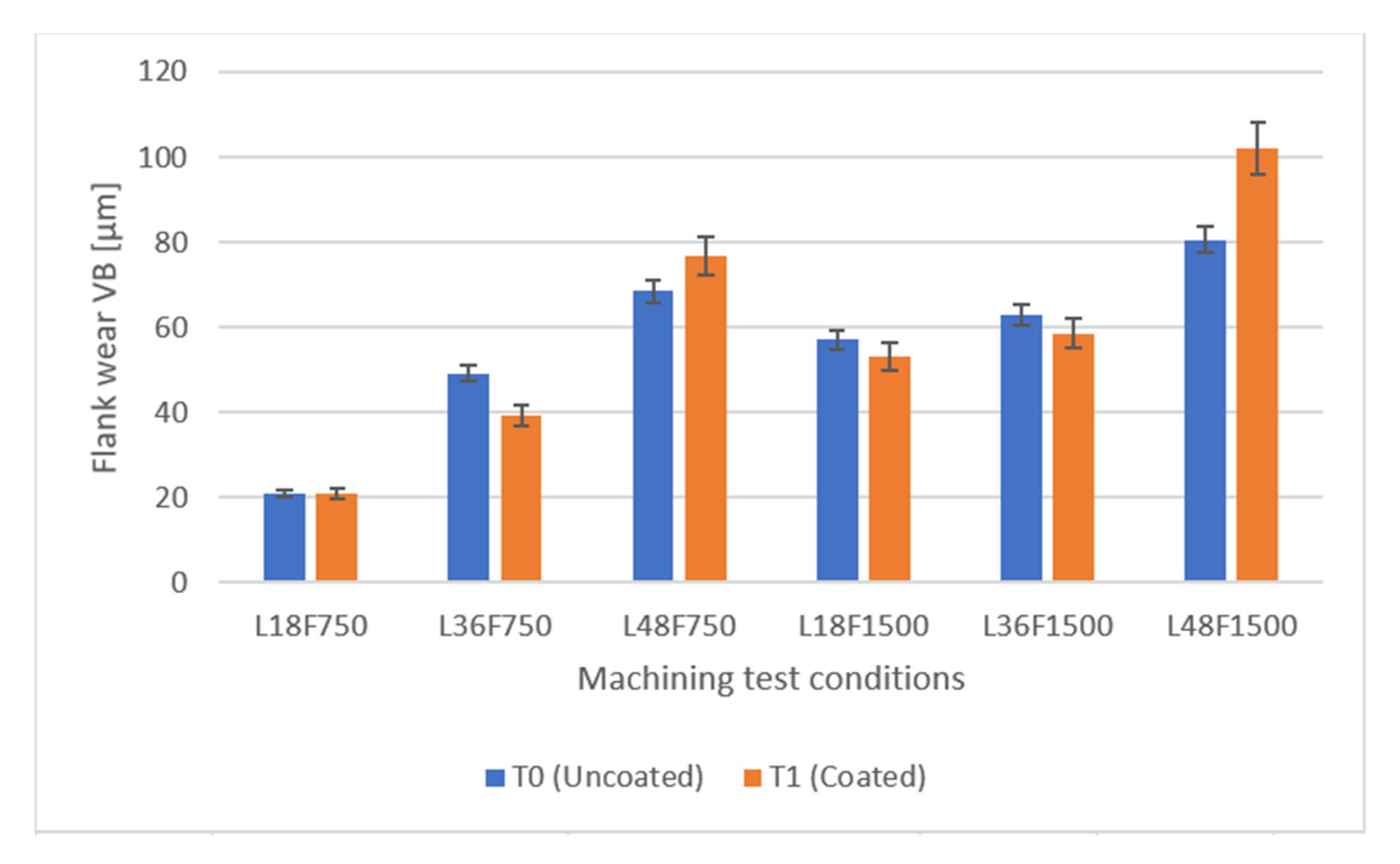
  • Regarding the surface roughness of the machined part, it was clearly noticed that the feed rate had a high influence on this parameter, with values of surface roughness increasing by up to four times from the feed rate of 750 mm/min to 1500 mm/min. This was registered for both uncoated and coated tools; however, the coated tools produced better results for cutting lengths of up to 36 m, with surface quality deterioration from that point onward. The uncoated tools produced an overall better surface quality for the maximum cutting length of 48 m.
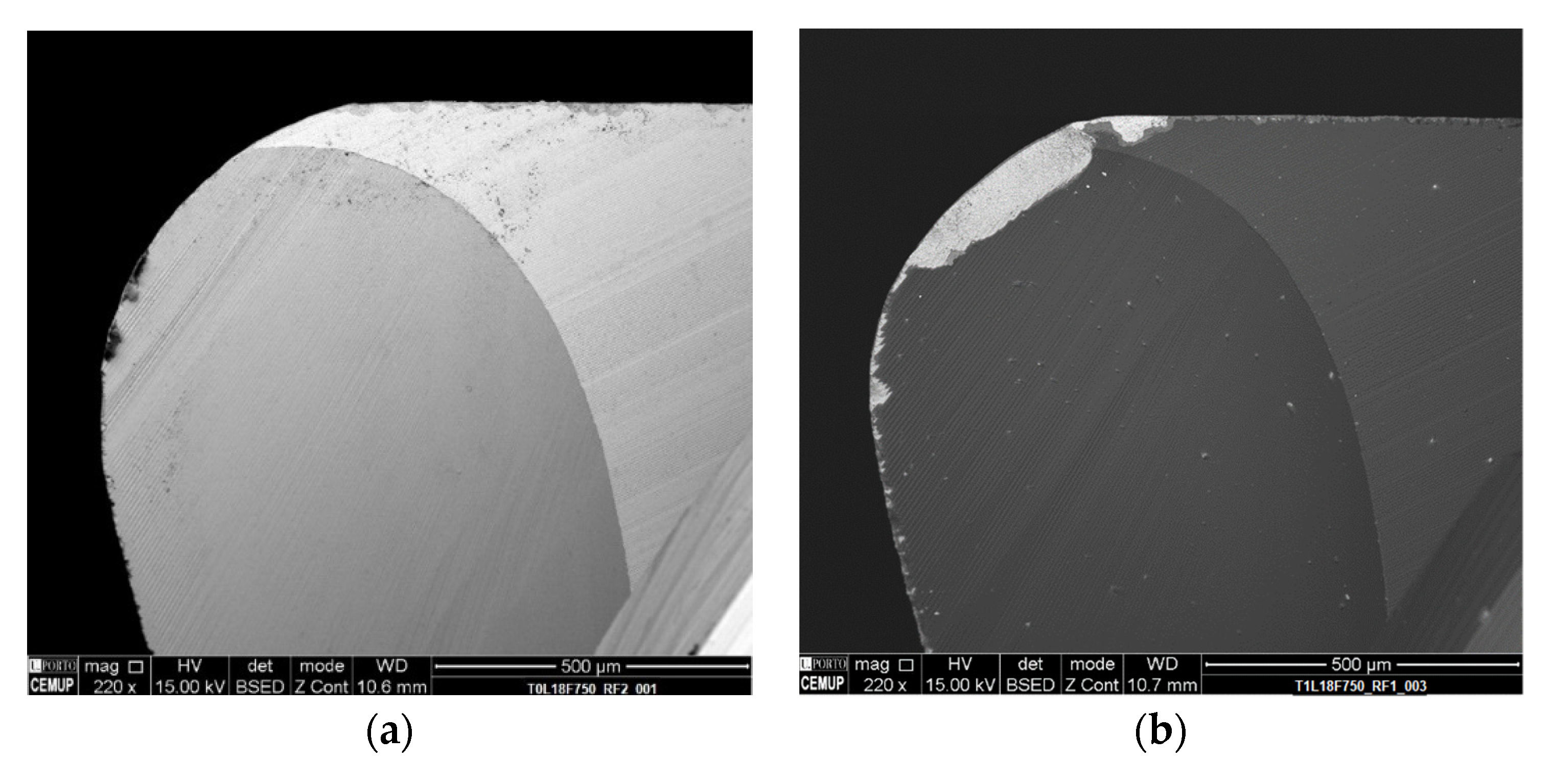
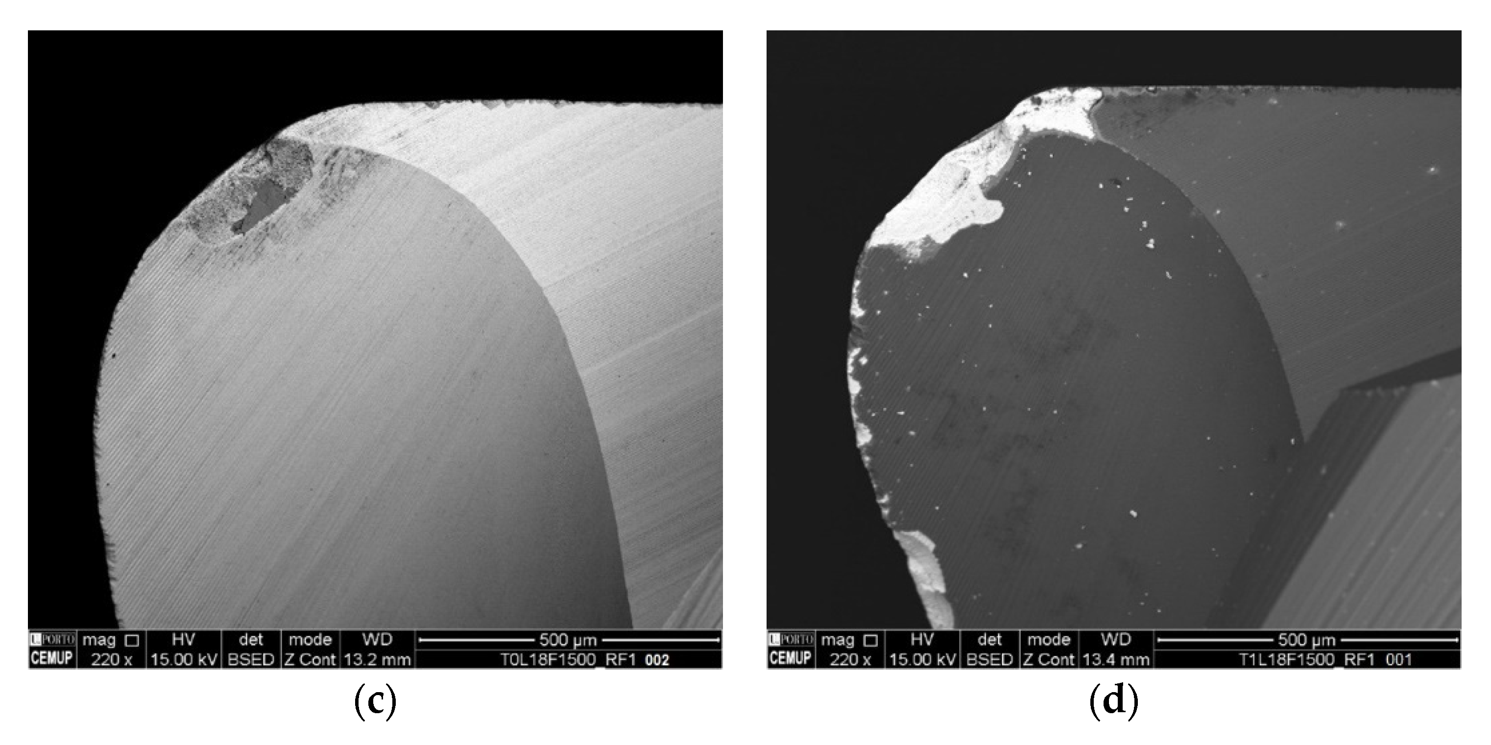
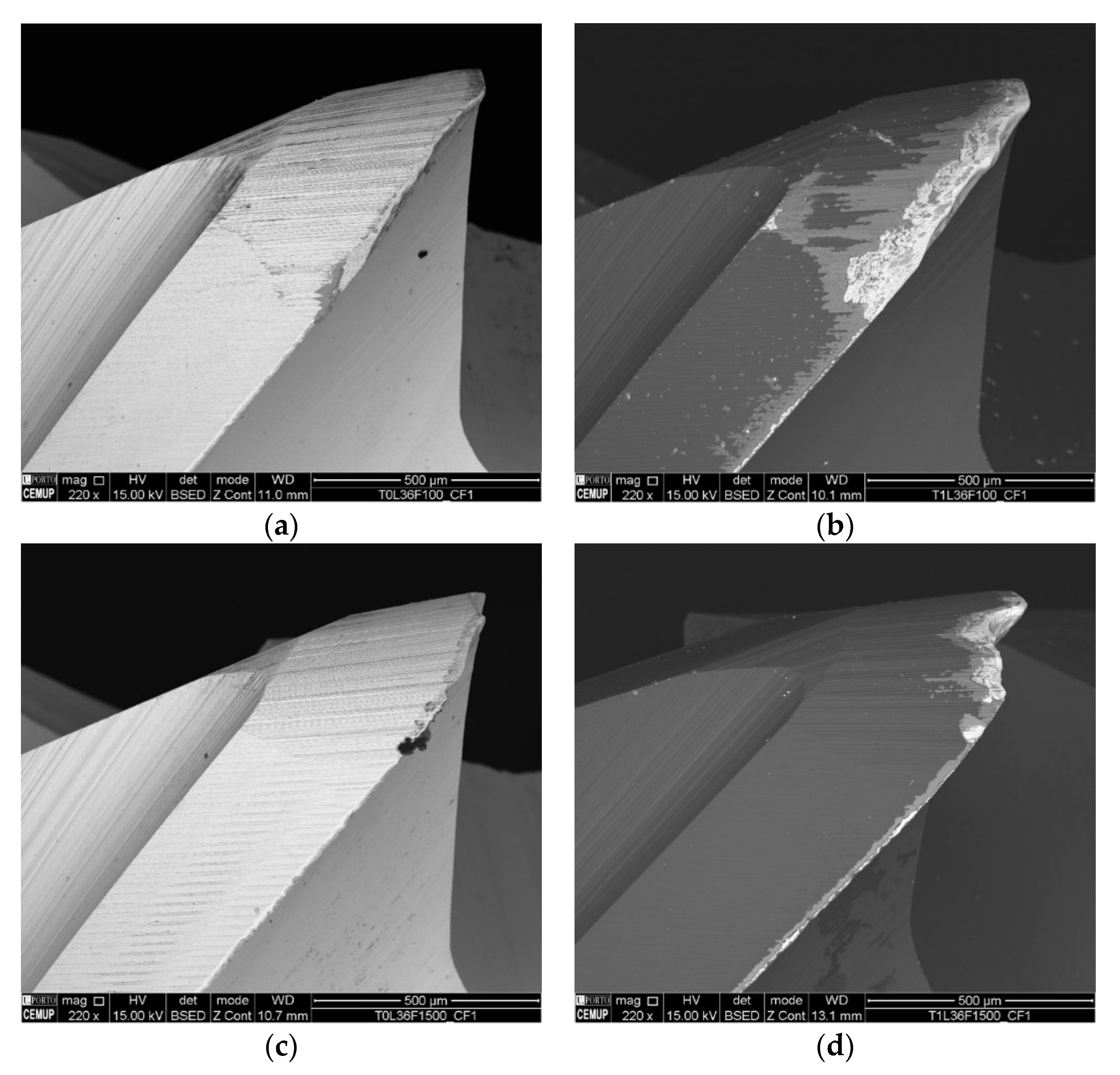
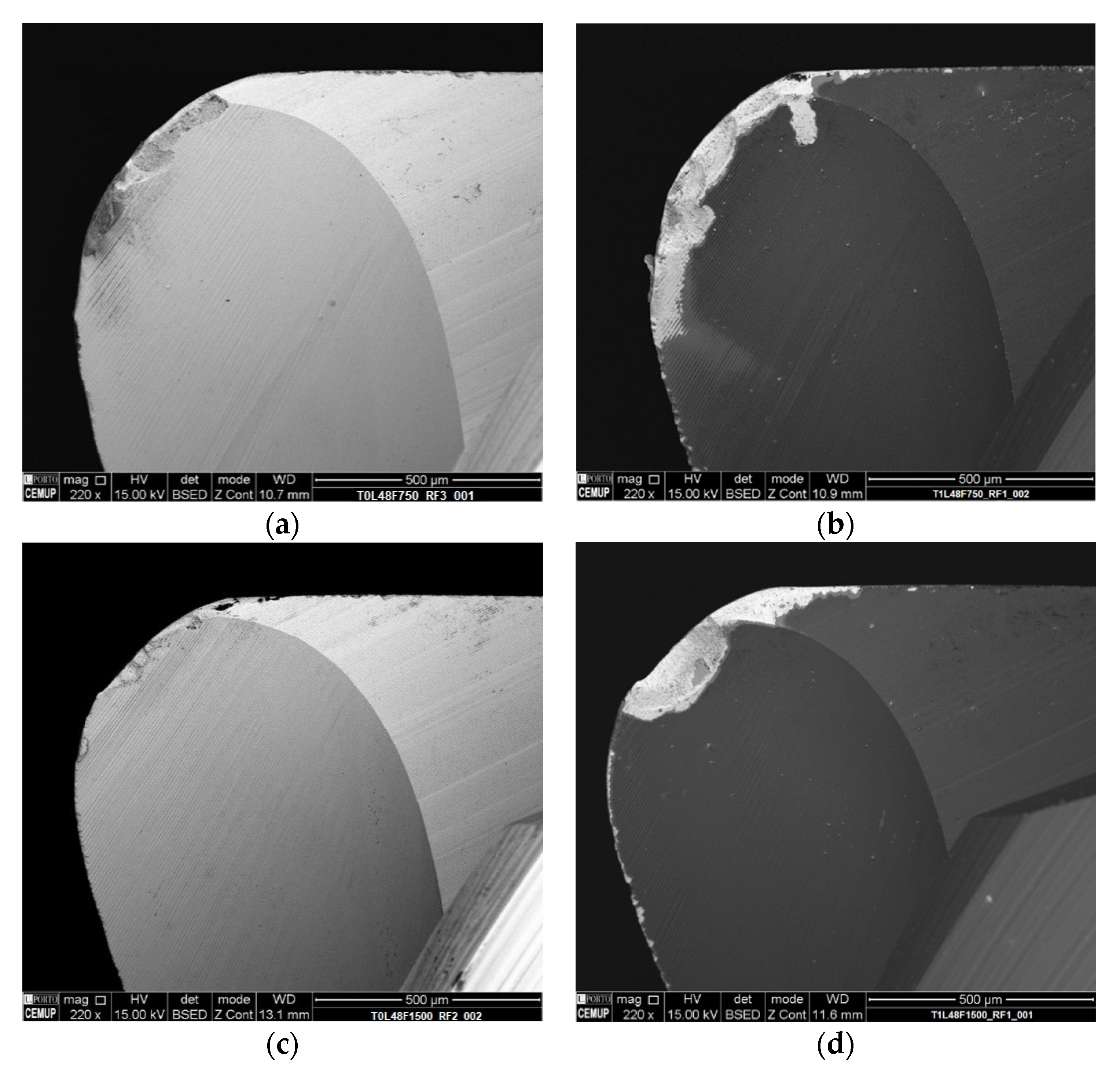
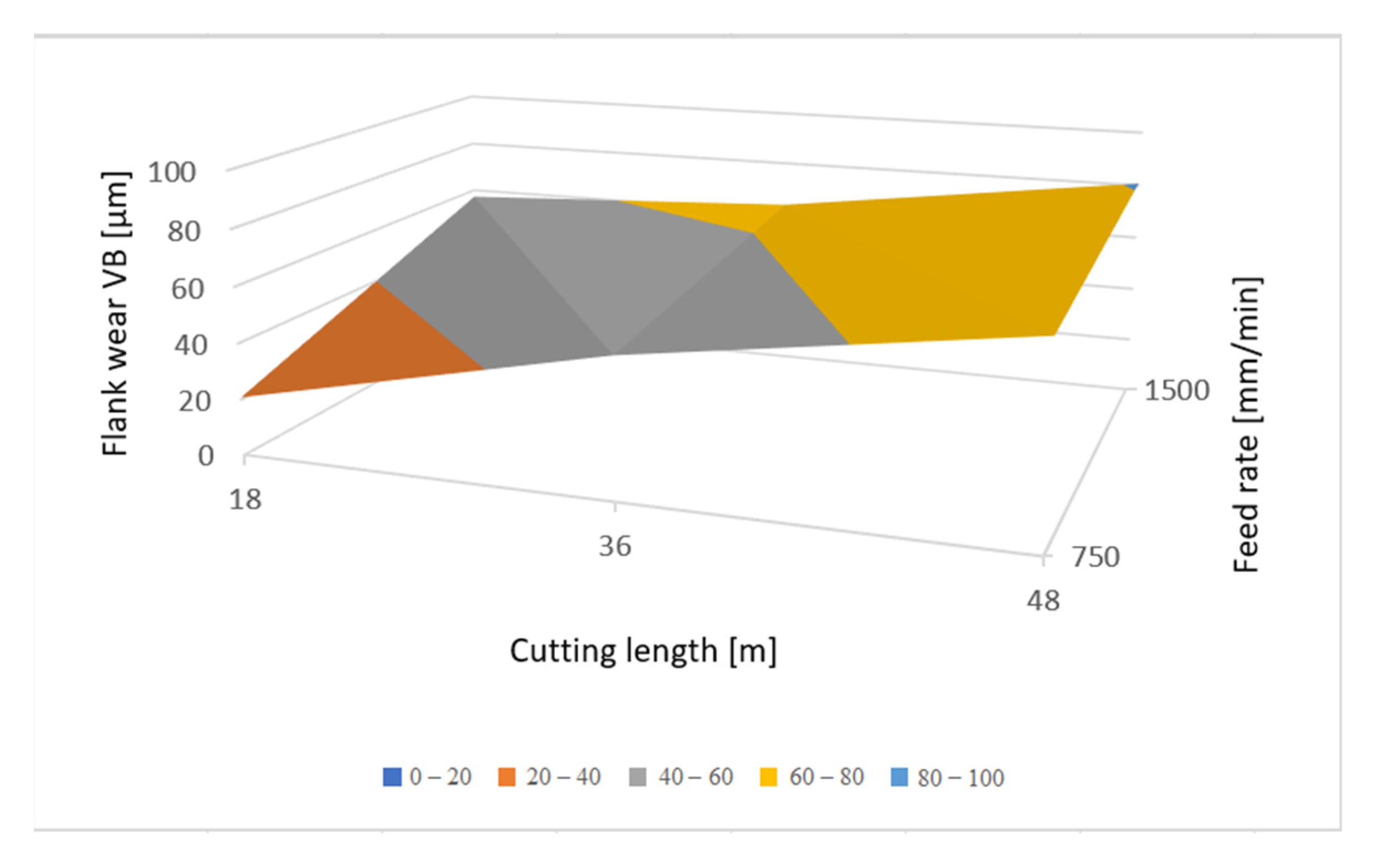
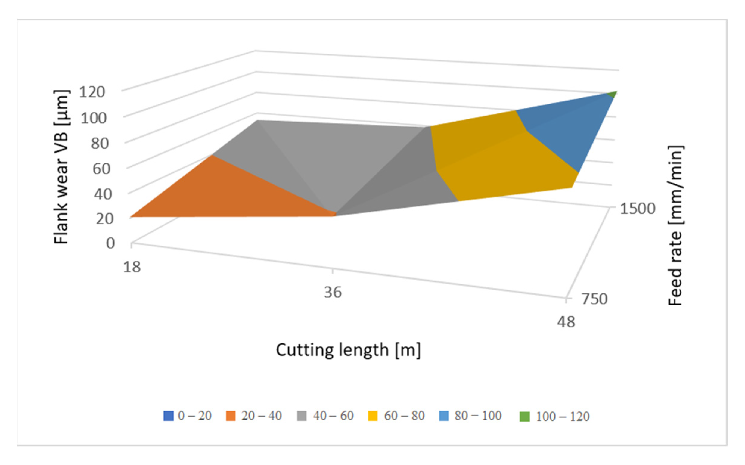
  • The tool’s wear behavior was similar with an increase in the feed rate values, with the sustained flank wear being more severe for a feed rate value of 1500 mm/min. A flank wear of 80.71 µm and 102.3 µm was registered for uncoated and coated tools, respectively. These maximum flank wear values were registered for higher cutting lengths, with the coated tools experiencing considerably more wear for higher cutting lengths than the uncoated tools. However, for cutting lengths of 18 and 36 m, these tools exhibited less wear than the uncoated ones. Thus, it seems that the 36-m cutting length represents a turning point for the tools’ wear behavior. For the 48-m cutting length, the uncoated tools presented a better behavior than the coated ones, thus, the improved behavior of the coated tools ends at about a cutting length of 36 m.
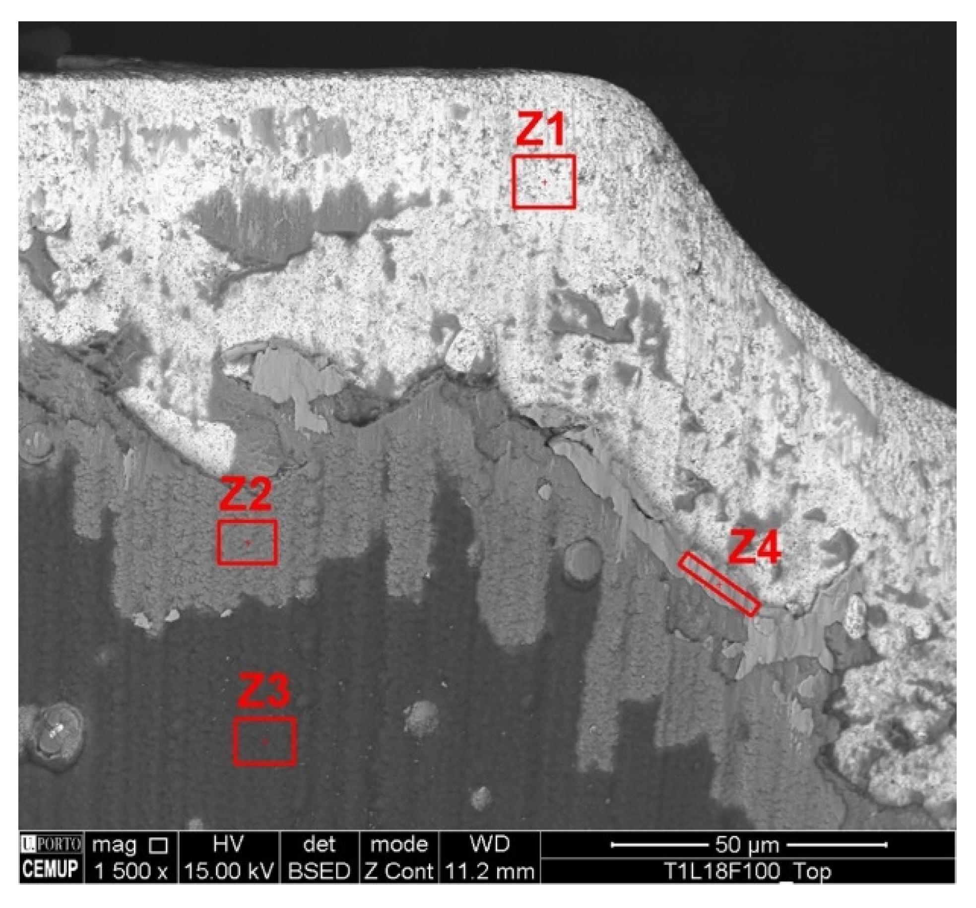
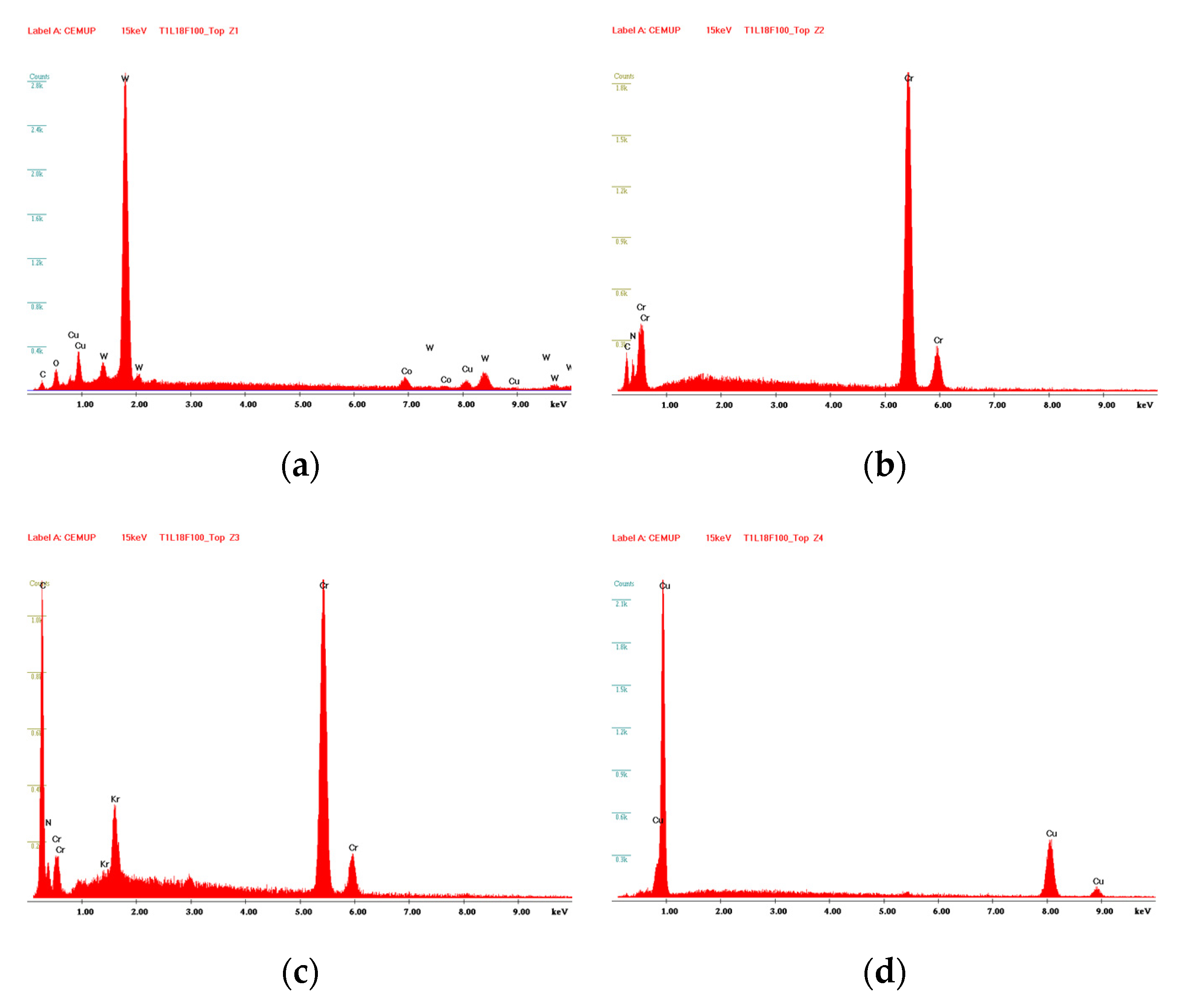
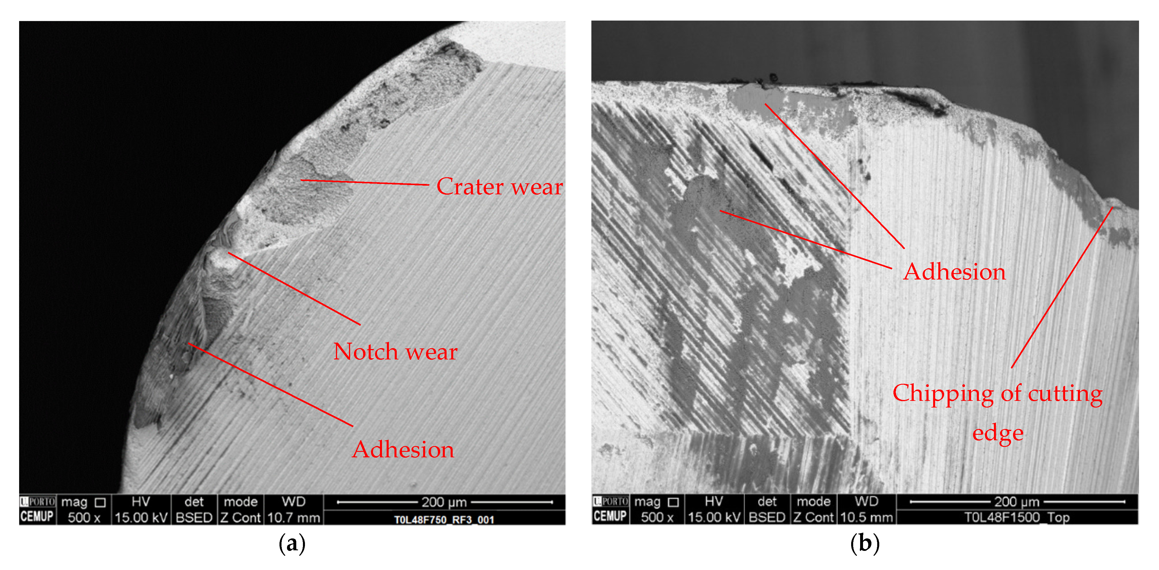
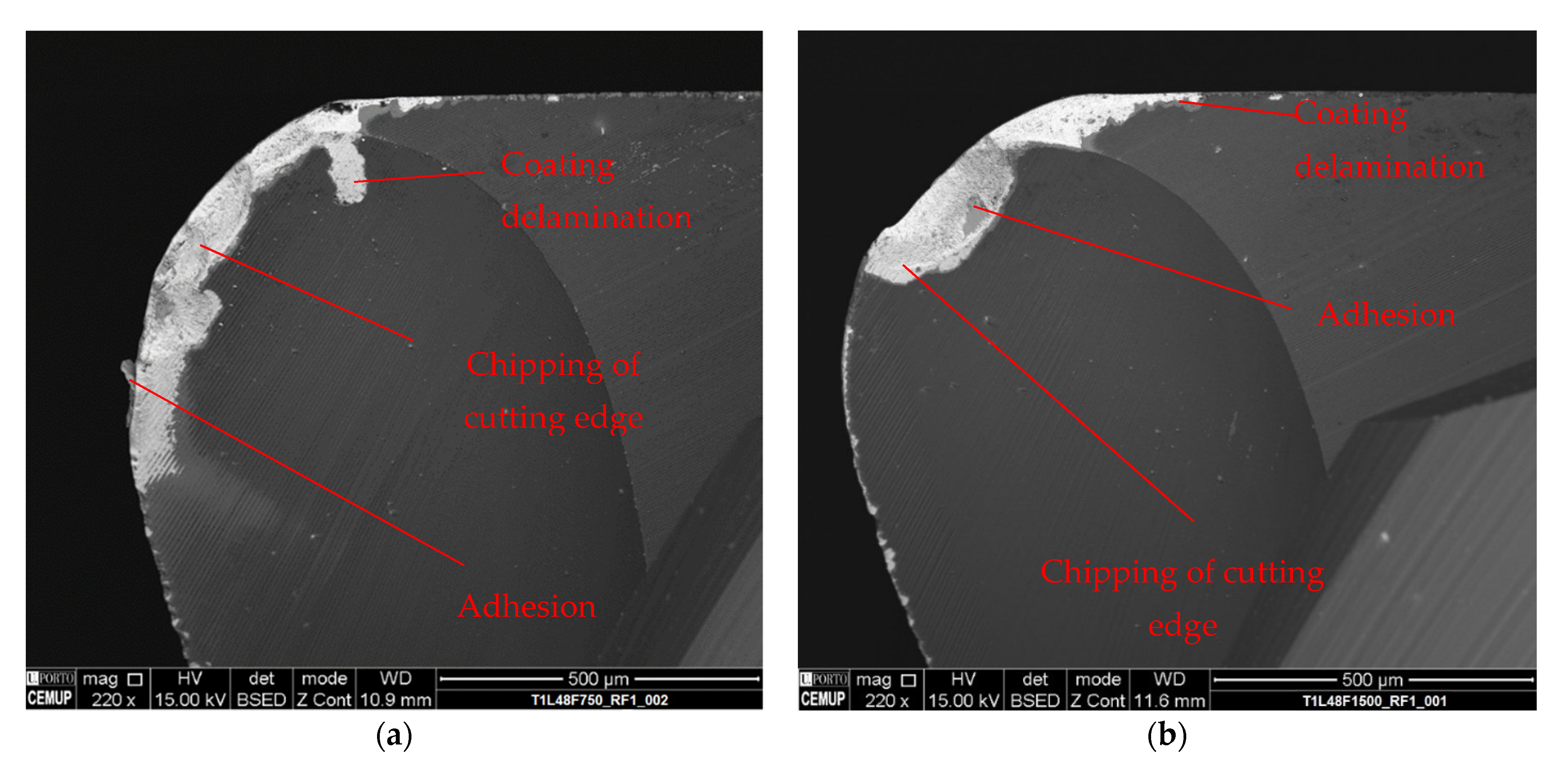
  • Regarding the tool wear mechanisms, it was possible to observe that the main wear mechanisms were adhesion, tool chipping, and abrasion. In addition to these, coating delamination was registered in the coated tools. Tool chipping and cutting-edge breakage was more prominent for higher values of feed rate, and was registered in both coated and uncoated tools.
Both the coated and uncoated tools presented similar wear behaviors, with the coated tools exhibiting less wear and producing a better machined quality in the beginning of the tests. However, for longer cutting lengths the coated tools were outperformed by the uncoated ones, producing a worse surface finish and suffering more wear. This indicated that this coating was not best suited for finishing operations of copper-beryllium alloys, following the described machining strategy. The development of different machining strategies for finishing can prove beneficial for the optimization of the wear behavior of these tools, a subject that can be explored in future work.
It was also found that feed rate has a very high influence on the produced machining quality, with lower feed rates producing the lowest surface roughness values. Preliminary tests carried out at a feed rate value of 350 mm/min produced highly satisfactory values, for both coated and uncoated tools, with the values obtained from each of the tool types being very similar; however, in this case, the uncoated tool outperformed the coated tool for every cutting length value, i.e., it produced an overall better surface finish. By lowering the feed rate, it is possible to skip additional steps that are required to produce mold parts, such as grinding and polishing operations, which are very usual regarding molds for shiny surfaces. This opens a new avenue of future study regarding the influence of feed-rate on the machining of these alloys, and how this can contribute for the optimization of the processing of copper-beryllium alloys. Regarding the study of this lower feed-rate, more intermediate stages should be inserted, accompanied by an analysis of the wear of both tools throughout the test. Furthermore, other machining parameters (such as cutting speed and even different lubrication conditions) and strategy influences on the surface roughness could be evaluated.

Author Contributions

Conceptualization, F.J.G.S. and V.F.C.S.; methodology, J.C. and F.J.G.S.; formal analysis, F.J.G.S., V.F.C.S., J.C., J.S.F., G.P. and A.B.; investigation, V.F.C.S. and J.C.; resources, V.F.C.S., J.S.F., G.P. and A.B.; data curation, J.C. and J.S.F.; writing—original draft preparation, V.F.C.S. and J.C.; writing—review and editing, F.J.G.S., V.F.C.S., J.S.F., G.P. and A.B.; supervision, F.J.G.S. and J.S.F.; project administration, F.J.G.S., G.P. and A.B. All authors have read and agreed to the published version of the manuscript.

Funding

This research received no external funding.

Institutional Review Board Statement

Not applicable.

Informed Consent Statement

Not applicable.

Data Availability Statement

Not applicable.

Acknowledgments

The authors would like to thank Ing. Nuno André from INOVATOOLS, Lda. (Marinha Grande, Portugal) due to his precious collaboration in providing the necessary tools for this work, as well as Ing. Ricardo Alexandre from TEandM, S.A. company for his crucial help in providing the necessary coatings on the tools. The collaboration of Rui Rocha from CEMUP (Porto, Portugal) is also deeply appreciated in SEM sessions, providing accurate equipment control and useful suggestions in phenomena identification and analysis. The help provided by Ing. Fátima Andrade from ISEP is also deeply acknowledged regarding the precious collaboration in cutting and preparing the samples for SEM analysis. The present work was carried out and funded under the scope of the project ON-SURF (ANI | P2020 | POCI-01-0247-FEDER-024521, co-funded by Portugal 2020 and FEDER, through COMPETE 2020-Operational Programme for Competitiveness and Internationalisation. Authors also thank INEGI-Instituto de Ciência e Inovação em Engenharia Mecânica e Engenharia Industria, due to its support.

Conflicts of Interest

The authors declare no conflict of interest.

References

  1. Millett, J.; Whiteman, G.; Park, N.; Case, S.; Appleby-Thomas, G. The effects of heat treatment upon the shock response of a copper-beryllium alloy. Acta Mater. 2019, 165, 678–685. [Google Scholar] [CrossRef]
  2. Zhong, Z.; Leong, M.; Liu, X. The wear rates and performance of three mold insert materials. Mater. Des. 2011, 32, 643–648. [Google Scholar] [CrossRef]
  3. Lipa, M.; Durocher, A.; Tivey, R.; Huber, T.; Schedler, B.; Weigert, J. The use of copper alloy CuCrZr as a structural material for actively cooled plasma facing and in vessel components. Fusion Eng. Des. 2005, 75–79, 469–473. [Google Scholar] [CrossRef]
  4. Amorim, F.L.; Weingaertner, W.L. Die-sinking electrical discharge machining of a high-strength copper-based alloy for injection molds. J. Braz. Soc. Mech. Sci. Eng. 2004, 26, 137–144. [Google Scholar] [CrossRef] [Green Version]
  5. Aggarwal, V.; Pruncu, C.I.; Singh, J.; Sharma, S.; Pimenov, D.Y. Empirical Investigations during WEDM of Ni-27Cu-3.15Al-2Fe-1.5Mn Based Superalloy for High Temperature Corrosion Resistance Applications. Materials 2020, 13, 3470. [Google Scholar] [CrossRef]
  6. Mouralova, K.; Benes, L.; Prokes, T.; Bednar, J.; Zahradnicek, R.; Jankovych, R.; Fries, J.; Vontor, J. Analysis of the Machinability of Copper Alloy Ampcoloy by WEDM. Materials 2020, 13, 893. [Google Scholar] [CrossRef] [Green Version]
  7. Gouveia, R.M.; Silva, F.J.G.; Reis, P.; Baptista, A.P.M. Machining Duplex Stainless Steel: Comparative Study Regarding End Mill Coated Tools. Coatings 2016, 6, 51. [Google Scholar] [CrossRef] [Green Version]
  8. Silva, F.J.G.; Martinho, R.P.; Martins, C.; Lopes, H.; Gouveia, R.M. Machining GX2CrNiMoN26-7-4 DSS Alloy: Wear Analysis of TiAlN and TiCN/Al2O3/TiN Coated Carbide Tools Behavior in Rough End Milling Operations. Coatings 2019, 9, 392. [Google Scholar] [CrossRef] [Green Version]
  9. Sousa, V.F.; Silva, F.; Alexandre, R.; Fecheira, J. Study of the wear behaviour of TiAlSiN and TiAlN PVD coated tools on milling operations of pre-hardened tool steel. Wear 2021, 476, 203695. [Google Scholar] [CrossRef]
  10. Suárez, A.; Veiga, F.; Polvorosa, R.; Artaza, T.; Holmberg, J.; de Lacalle, L.L.; Wretland, A. Surface integrity and fatigue of non-conventional machined Alloy 718. J. Manuf. Process. 2019, 48, 44–50. [Google Scholar] [CrossRef]
  11. Polvorosa, R.; Suárez, A.; de Lacalle, L.L.; Cerrillo, I.; Wretland, A.; Veiga, F. Tool wear on nickel alloys with different coolant pressures: Comparison of Alloy 718 and Waspaloy. J. Manuf. Process. 2017, 26, 44–56. [Google Scholar] [CrossRef]
  12. Suárez, A.; Veiga, F.; de Lacalle, L.L.; Polvorosa, R.; Wretland, A. An investigation of cutting forces and tool wear in turning of Haynes 282. J. Manuf. Process. 2019, 37, 529–540. [Google Scholar] [CrossRef]
  13. Suárez, A.; De Lacalle, L.N.L.; Polvorosa, R.; Veiga, F.; Wretland, A. Effects of high-pressure cooling on the wear patterns on turning inserts used on alloy IN718. Mater. Manuf. Process. 2017, 32, 678–686. [Google Scholar] [CrossRef]
  14. Rivero, A.; Aramendi, G.; Herranz, S.; de Lacalle, L.N.L. An experimental investigation of the effect of coatings and cutting parameters on the dry drilling performance of aluminium alloys. Int. J. Adv. Manuf. Technol. 2005, 28, 1–11. [Google Scholar] [CrossRef]
  15. Kumar, S.; Saravanan, I.; Patnaik, L. Optimization of surface roughness and material removal rate in milling of AISI 1005 carbon steel using Taguchi approach. Mater. Today Proc. 2020, 22, 654–658. [Google Scholar] [CrossRef]
  16. Masooth, P.H.S.; Jayakumar, V.; Bharathiraja, G. Experimental investigation on surface roughness in CNC end milling process by uncoated and TiAlN coated carbide end mill under dry conditions. Mater. Today Proc. 2020, 22, 726–736. [Google Scholar] [CrossRef]
  17. Bohley, M.; Kieren-Ehses, S.; Heberger, L.; Kirsch, B.; Aurich, J.C. Size limitations and wear behavior of TiB2 coated micro end mills (Ø < 50 µm) when machining cp-titanium. Procedia CIRP 2018, 71, 187–191. [Google Scholar] [CrossRef]
  18. Santhakumar, J.; Iqbal, U.M.; Prakash, M. Taguchi-Grey Relational Based Multi-Response Optimization on the Performance of Tool Coating Thickness in Pocket Milling. Mater. Today Proc. 2018, 5, 13422–13428. [Google Scholar] [CrossRef]
  19. Krishnan, B.R.; Ramesh, M. Optimization of machining process parameters in CNC turning process of IS2062 E250 Steel using coated carbide cutting tool. Mater. Today Proc. 2020, 21, 346–350. [Google Scholar] [CrossRef]
  20. Phokobye, S.; Daniyan, I.; Tlhabadira, I.; Masu, L.; VanStaden, L. Model Design and Optimization of Carbide Milling Cutter for Milling Operation of M200 Tool Steel. Procedia CIRP 2019, 84, 954–959. [Google Scholar] [CrossRef]
  21. Sousa, V.F.C.; Silva, F.J.G. Recent Advances in Turning Processes Using Coated Tools—A Comprehensive Review. Metals 2020, 10, 170. [Google Scholar] [CrossRef] [Green Version]
  22. Sousa, V.F.C.; Silva, F.J.G. Recent Advances on Coated Milling Tool Technology—A Comprehensive Review. Coatings 2020, 10, 235. [Google Scholar] [CrossRef] [Green Version]
  23. Elosegui, I.; Alonso, U.; De Lacalle, L.N.L. PVD coatings for thread tapping of austempered ductile iron. Int. J. Adv. Manuf. Technol. 2017, 91, 2663–2672. [Google Scholar] [CrossRef]
  24. Gil Del Val, A.; Veiga, F.; Pereira, O.; De Lacalle, L.N.L. Threading Performance of Different Coatings for High-Speed Steel Tapping. Coatings 2020, 10, 464. [Google Scholar] [CrossRef]
  25. Akmal, M.; Yazgi, S.; Lazoglu, I.; Akgun, A. Friction Analysis on AlTiN Coated and Uncoated Carbide Tools in Milling of Al7050. In Proceedings of the 8th International Symposium on Machining, Antalya, Turkey, 8–10 November 2017. [Google Scholar]
  26. Sousa, V.F.C.; Silva, F.J.G.; Fecheira, J.S.; Lopes, H.M.; Martinho, R.P.; Casais, R.B.; Ferreira, L.P. Cutting Forces Assessment in CNC Machining Processes: A Critical Review. Sensors 2020, 20, 4536. [Google Scholar] [CrossRef] [PubMed]
  27. Martinho, R.; Silva, F.; Baptista, A. Cutting forces and wear analysis of Si3N4 diamond coated tools in high-speed machining. Vacuum 2008, 82, 1415–1420. [Google Scholar] [CrossRef] [Green Version]
  28. Martinho, R.; Silva, F.; Baptista, A. Wear behaviour of uncoated and diamond coated Si3N4 tools under severe turning conditions. Wear 2007, 263, 1417–1422. [Google Scholar] [CrossRef] [Green Version]
  29. Wang, C.; Wang, X.; Sun, F. Tribological behavior and cutting performance of monolayer, bilayer and multilayer diamond coated milling tools in machining of zirconia ceramics. Surf. Coat. Technol. 2018, 353, 49–57. [Google Scholar] [CrossRef]
  30. Vereschaka, A.; Gurin, V.; Oganyan, M.; Oganyan, G.; Bublikov, J.; Shein, A. Increase in tool life for end milling titanium alloys using tools with multilayer composite nanostructured modified coatings. Procedia CIRP 2019, 81, 1412–1416. [Google Scholar] [CrossRef]
  31. Rodríguez-Barrero, S.; Fernández-Larrinoa, J.; Azkona, I.; De Lacalle, L.N.L.; Polvorosa, R. Enhanced Performance of Nanostructured Coatings for Drilling by Droplet Elimination. Mater. Manuf. Process. 2016, 31, 593–602. [Google Scholar] [CrossRef]
  32. Fernández-Abia, A.I.; Barreiro, J.; De Lacalle, L.N.L.; González-Madruga, D. Effect of mechanical pre-treatments in the behaviour of nanostructured PVD-coated tools in turning. Int. J. Adv. Manuf. Technol. 2014, 73, 1119–1132. [Google Scholar] [CrossRef]
  33. Viana, R.; de Lima, M.S.F.; Sales, W.F.; da Silva, W.M., Jr.; Machado, Á.R. Laser texturing of substrate of coated tools—Performance during machining and in adhesion tests. Surf. Coat. Technol. 2015, 276, 485–501. [Google Scholar] [CrossRef]
  34. Mishra, S.; Ghosh, S.; Aravindan, S. Characterization and machining performance of laser-textured chevron shaped tools coated with AlTiN and AlCrN coatings. Surf. Coat. Technol. 2018, 334, 344–356. [Google Scholar] [CrossRef]
  35. Baptista, A.; Silva, F.; Porteiro, J.; Míguez, J.; Pinto, G. Sputtering Physical Vapour Deposition (PVD) Coatings: A Critical Review on Process Improvement and Market Trend Demands. Coatings 2018, 8, 402. [Google Scholar] [CrossRef] [Green Version]
  36. Martinho, R.P.; Silva, F.J.G.; Martins, C.; Lopes, H. Comparative study of PVD and CVD cutting tools performance in milling of duplex stainless steel. Int. J. Adv. Manuf. Technol. 2019, 102, 2423–2439. [Google Scholar] [CrossRef]
  37. Fernández-Abia, A.; Barreiro, J.; Fernández-Larrinoa, J.; de Lacalle, L.L.; Fernández-Valdivielso, A.; Pereira, O. Behaviour of PVD Coatings in the Turning of Austenitic Stainless Steels. Procedia Eng. 2013, 63, 133–141. [Google Scholar] [CrossRef] [Green Version]
  38. Klocke, F.; Krieg, T. Coated Tools for Metal Cutting—Features and Applications. CIRP Ann. 1999, 48, 515–525. [Google Scholar] [CrossRef]
  39. Nunes, V.; Silva, F.; Andrade, M.; Alexandre, R.; Baptista, A. Increasing the lifespan of high-pressure die cast molds subjected to severe wear. Surf. Coat. Technol. 2017, 332, 319–331. [Google Scholar] [CrossRef]
  40. Silva, F.; Martinho, R.; Alexandre, R.; Baptista, A. Increasing the wear resistance of molds for injection of glass fiber reinforced plastics. Wear 2011, 271, 2494–2499. [Google Scholar] [CrossRef] [Green Version]
  41. Mindivan, H. Corrosion and tribocorrosion behaviour of WC/C coating on beryllium-copper mould alloy. Mater. Today Proc. 2020, 27, 3114–3118. [Google Scholar] [CrossRef]
  42. Sharma, A.; Datta, D.; Balasubramaniam, R. An investigation of tool and hard particle interaction in nanoscale cutting of copper beryllium. Comput. Mater. Sci. 2018, 145, 208–223. [Google Scholar] [CrossRef]
  43. Sharma, A.; Joshi, S.S.; Datta, D.; Balasubramaniam, R. Modeling and analysis of tool wear mechanisms in diamond turning of copper beryllium alloy. J. Manuf. Process. 2020, 56, 439–450. [Google Scholar] [CrossRef]
  44. Devi, K.D.; Babu, K.S.; Reddy, K.H. Statistical Approach for Multi Criteria Optimization of Cutting Parameters of Turning on Heat Treated Beryllium Copper Alloy. J. Eng. Sci. Technol. 2017, 12, 2213–2228. [Google Scholar]
  45. Alagarsamy, S.; Ravichandran, M.; Meignanamoorthy, M.; Chanakyan, C.; Kumar, S.D.; Sakthivelu, S. Influence of CNC turning variables on high strength Beryllium-Copper (C17200) alloy using tungsten carbide insert. Mater. Today Proc. 2020, 27, 925–930. [Google Scholar] [CrossRef]
  46. Shihan, M.; Chandradass, J.; Kannan, T.T.M. Investigation of vibration analysis during end milling process of monel alloy. Mater. Today Proc. 2021, 39, 695–699. [Google Scholar] [CrossRef]
  47. Shihan, M.; Chandradass, J.; Kannan, T.T.M.; Sivagami, S.M. Machining feasibility and sustainability study on end milling process of Monel alloy. Mater. Today Proc. 2021, 45, 7162–7165. [Google Scholar] [CrossRef]
  48. Zuo, J.; Lin, Y.; Zheng, J.; Zhong, P.; He, M. An investigation of thermal-mechanical interaction effect on PVD coated tool wear for milling Be/Cu alloy. Vacuum 2019, 167, 271–279. [Google Scholar] [CrossRef]
  49. Zuo, J.; Lin, Y.; He, M. An Investigation of the Adhesive Effect on the Flank Wear Properties of a WC/Co-based TiAlN-Coated Tool for Milling a Be/Cu Alloy. Metals 2019, 9, 444. [Google Scholar] [CrossRef] [Green Version]
Figure 1. Positioning and lebelling used the y«the tools’ analyses: (a) Label used in the tools’ analyses; (b) label used for rake face of cutting knife 1.
Applsci 11 07762 g001
Figure 2. Coating characterization: (a) identification of the different layers (Z1—CrN, Z2—DLC, Z3—CrN, Z4—DLC); (b) thickness measurement of the coating.
Applsci 11 07762 g002
Figure 3. EDS spectra for each of the zones in Figure 2: (a) Z1; (b) Z2; (c) Z3; (d) Z4.
Applsci 11 07762 g003
Figure 4. Surface graph of the machined surface roughness produced by the uncoated tools for each of the tested conditions.
Applsci 11 07762 g004
Figure 5. Surface graph of the machined surface roughness of the coated tools for each of the tested conditions.
Applsci 11 07762 g005
Figure 6. Comparison of the surface roughness values of uncoated and coated tools for each of the machining conditions.
Applsci 11 07762 g006
Figure 7. Comparison of the surface roughness values of uncoated and coated tools for the tests conducted at 350 mm/min feed rate.
Applsci 11 07762 g007
Figure 8. SEM images at 220× magnification of the rake face of tested tools under the conditions of: (a) T0L18F750; (b) T1L18F750; (c) T0L18F1500; (d) T1L18F1500.
Applsci 11 07762 g008aApplsci 11 07762 g008b
Figure 9. SEM images at 220× magnification of the clearance face of tested tools under the conditions of: (a) T0L18F750; (b) T1L18F750; (c) T0L18F1500; (d) T1L18F1500.
Applsci 11 07762 g009
Figure 10. SEM images at 220× magnification of the rake face of tested tools under the conditions of: (a) T0L48F750; (b) T1L48F750; (c) T0L48F1500; (d) T1L48F1500.
Applsci 11 07762 g010
Figure 11. Surface graph of the mean value of measured flank wear (VB) of the uncoated tools for each of the tested conditions.
Applsci 11 07762 g011
Figure 12. Surface graph of the mean value of measured flank wear (VB) of the coated tools for each of the tested conditions.
Applsci 11 07762 g012
Figure 13. Comparison of the sustained flank wear of uncoated and coated tools for each of the machining conditions.
Applsci 11 07762 g013
Figure 14. (a) Wear mechanisms present on an uncoated tools’ clearance face, tested at 36 m of cutting length and 750 mm/min feed rate; (b) EDS spectra of Z1; (c) EDS spectra of Z2.
Applsci 11 07762 g014
Figure 15. Wear mechanisms registered on a coated tools’ top, identifying four zones for EDS analysis.
Applsci 11 07762 g015
Figure 16. EDS spectra of Figure 16 zones: (a) Z1; (b) Z2; (c) Z3; (d) Z4.
Applsci 11 07762 g016
Figure 17. (a) Wear mechanisms registered on the rake face sustained by an uncoated tool tested at a cutting length of 48 m and 750 mm/min feed rate; (b) wear mechanisms registered on tools’ top sustained by an uncoated tool tested at a cutting length of 48 m and 1500 mm/min feed rate.
Applsci 11 07762 g017
Figure 18. SEM images of coated tools rake face tested at a cutting length of 48 m, at 220× magnification: (a) for a coated tool tested at a feed rate value of 750 mm/min and (b) coated tool tested at a feed rate value of 1500 mm/min.
Applsci 11 07762 g018
Table 1. Chemical composition of Ampcoloy 83 (wt%).
Cobalt + NickelBerylliumCopperOthers
0.51.997.10.5
Table 2. Mechanical properties of Ampcoloy 83.
Mechanical PropertiesValue
Tensile strength—Rm [MPa]1250
Yield strength—Rp 0.5 [MPa]1000
Elongation—A [%]4
Modulus of elasticity—E [GPa]131
Table 3. Parameters used in the PVD coating deposition.
ParameterChromium Nitride (CrN)DLC
Argon+ flow rate160 mL240 mL
Krypton flow rate80 mL180 mL
Working pressure600 MPa600 MPa
Bias−60 V−75 V
TargetChromiumGraphite
Number of targets31
Current density9 W/cm213.5 W/cm2
Time1.5 h2.5 h
Table 4. Parameters used in the machining tests.
CoatingCutting Speed (Vc)Feed Rate (Vf)Depth of Cut (ap)Radial Depth of Cut (ae)Cutting Length
[m/min][mm/min][mm][mm][m]
T0L18F750Uncoated1267500.52.518
T0L36F750Uncoated1267500.52.536
T0L48F750Uncoated1267500.52.548
T0L18F1500Uncoated12615000.52.518
T0L36F1500Uncoated12615000.52.536
T0L48F1500Uncoated12615000.52.548
T1L18F750CrN + DLC1267500.52.518
T1L36F750CrN + DLC1267500.52.536
T1L48F750CrN + DLC1267500.52.548
T1L18F1500CrN + DLC12615000.52.518
T1L36F1500CrN + DLC12615000.52.536
T1L48F1500CrN + DLC12615000.52.548
Labelling TxLyFz: x—Coated; 0—Uncoated; L—Cutting Length; y—Length Value; z—Feed Rate.
Table 5. Layer composition and average measured thickness.
LayerCompositionThickness [μm]
Z1CrN2.689 ± 0.081
Z2DLC0.271 ± 0.020
Z3CrN0.570 ± 0.031
Z4DLC0.601 ± 0.018
Table 6. Surface roughness values registered for each of the tested conditions.
Tool ReferenceRa [μm]
T0L18F7500.102 ± 0.005
T0L36F7500.128 ± 0.006
T0L48F7500.137 ± 0.007
T1L18F7500.096 ± 0.020
T1L36F7500.134 ± 0.023
T1L48F7500.244 ± 0.030
T0L18F15000.399 ± 0.048
T0L36F15000.459 ± 0.051
T0L48F15000.595 ± 0.012
T1L18F15000.400 ± 0.019
T1L36F15000.572 ± 0.022
T1L48F15000.800 ± 0.040
Publisher’s Note: MDPI stays neutral with regard to jurisdictional claims in published maps and institutional affiliations.

