
Self-Grinding Silage Knife Strengthened with Ni–WC Alloy Prepared by Laser Cladding
by

Lingfeng Xu
1,2,3, 
Zhanhua Song
1,2,3,*,
Mingxiang Li
1,
Fade Li
1,2,3,
Jing Guo
1,2,3 and
Ming Gao
1,2,3,* 1
Mechanical and Electronic Engineering College, Shandong Agricultural University, Taian 271018, China
2
Shandong Provincial Key Laboratory of Horticultural Machineries and Equipments, Shandong Agricultural University, Taian 271018, China
3
Shandong Agricultural Equipment Intelligent Engineering Laboratory, Shandong Agricultural University, Taian 271018, China
*
Authors to whom correspondence should be addressed.
Appl. Sci. 2021, 11(21), 10236; https://0-doi-org.brum.beds.ac.uk/10.3390/app112110236
Submission received: 11 October 2021
/
Revised: 27 October 2021
/
Accepted: 29 October 2021
/
Published: 1 November 2021
(This article belongs to the Special Issue Mechanical Properties of Metal Alloy Surface: Measurement and Evaluation)
Abstract
:The working environment of agricultural cutting tools is poor, and the operational quality and efficiency are reduced after they become blunt. This study aimed to develop a high wear-resistant agriculture knife with a long life. A Ni–WC alloy, wear-resistant layer was prepared using laser cladding technology on one side of the cutting edge of a 65 Mn silage knife. A self-grinding edge was formed when the cladded knife was used, which improved the cutting quality and service life of the knife. The microstructure, phase, composition, and hardness distribution of the cladding layer were detected and analyzed. The impact toughness and wear resistance of the laser-cladded samples were analyzed, and the cladded knife was tested in the field. The results show that a cladded layer with a dense microstructure formed metallurgical bonds with the substrate. The microhardness was uniform across the cladded layer, and the average hardness of the micro Vickers was approximately 1000 HV(0.2), which was approximately three times the hardness of the substrate. The impact toughness and wear resistance of the coated knife were obviously higher than those of uncoated knives. The field tests showed that compared with a conventional 65 Mn knife, the self-grinding knife with laser cladding could maintain its sharp cutting shape after operation for 76 h, which greatly extended the service life of the knife. This study improved the service life of an agricultural cutting tool, which enhanced the cutting performance and efficiency at the same time.
1. Introduction
Cutting tools are used in a variety of agricultural machines for harvest. During usage, the cutting edge interacts with crop stalks and attachments of earth and sand, which induces friction and wear of the cutting edges. Friction is the primary cause of failure for agriculture knives, workpieces touching soil, etc. A gradual loss of materials subjected to abrasion mechanisms consumes more than 500,000 t of steel in China [1]. In addition, the blade angle and radius of the edge curvature increases when knives become dull, which leads to crop damage and poor cutting performance [2]. Self-grinding tool-making technology offers a good scheme for solving the above problems [3]. The cutting edge comprises a layered structure that consists of a wear-resistant layer and a lesser wear-resistant layer. As a result, different amounts of wear are produced at different layers of the cutting edge when cutting crops. The wear-resistant layer is exposed at the tip of the cutting edge. The geometry of the cutting edges can remain unchanged for long periods of time, which improves the service life and cutting quality of the knife [4].
Convenient techniques to induce effective compounds featuring a sharp gradation are coating, diffusion hardening, and local applied strengthening, e.g., one side of the cutting edge is carburized in order to obtain a self-grinding edge [5]. An Fe–Cr–C–V layer was prepared on a 65 Mn steel substrate by plasma surfacing welding technology. The over-lapped Fe–Cr–C cladding layer and dot-shaped Fe–Cr–C cladding layer were deposited by plasma-transferred arc (PTA) cladding on Hadfield steel [6,7]. Three kinds of steel plates were rolled into hardness gradient materials by vacuum rolling [8]. A two-part dental molding material was used to make casts of the cutting edge. The tip of the cutting edge in this case had a radius of less than 0.2 mm, which showed an excellent demanding operation of self-grinding [2].
Using the laser cladding technique to implement a coat on steel is a convenient approach to inducing a layered structure that overcomes the defects of other coating techniques. Metallurgical bonding can be formed for TIG welding, but the dilution ratio of TIG welding is higher than that of laser cladding, and the precision of the coating thickness does not meet the demands for preparing self-grinding knives. For the electroplating technique, only physical bonding takes place, which is prone to falling off. In addition, the thickness of the electroplating layer is between 1 and 3 μm, which is considerably lower than that of laser cladding. One the other hand, laser cladding can achieve metallurgical bonding between the layer and the substrate, a lower dilution, and a high precision of coating layer thickness, etc. [9]. Self-grinding knives prepared by laser cladding are used in forage choppers, and demonstrate significantly improved performance characteristics [10]. In addition to the coating technique, the material composition is the other important element influencing the performance of self-grinding knives. Ni-based alloys are an important material used to coat steel to obtain high wear resistance, with carbides and borides forming during coating [11]. Moreover, the wettability of the Ni element is excellent, which is the main element enhancing the bonds’ strength and the material’s toughness. Ni-based alloys have good compatibility with tungsten carbide (WC), which in particular holds high potential regarding wear resistance. WC can improve the hardness and wear resistance of the coating. The combination of the two can enhance the bonding strength and fracture toughness of the coating [12]. A layer consisting of nickel alloys and WC particles is made on one side of the cutting edge by laser cladding, which combines the hardness and toughness for this layer. Laser cladding also creates metallurgical bonding at interface between the substrate and the strengthening layer.
Steel of 65 Mn with high hardenability, toughness, and good wear resistance is usually used to make parts for working in the field [13]. The Ni–WC wear-resistance layer was prepared by laser cladding on one side of the cutting edge of a 65 Mn knife, which was used to harvest forage oat grass. Similar studies have not been published. The microstructure, impact toughness, and wear resistance of the strengthening layer were analyzed, and silage knives treated with laser cladding were assembled in a lawn mower to carry out field tests.
2. Materials and Methods
2.1. Experimental Materials
Figure 1 shows the experimental knife made of 65 Mn steel used in the lawn mower. A hardness of 65 Mn is approximately 350 HV (0.2). Before laser cladding, the surface of the knife was rubbed down with sandpaper (mesh number: 400–800) and washed with acetone (concentration: 99.5%). The chemical composition of the knife and nickel alloy used for cladding are given in Table 1. The grain size of the nickel and WC alloy was between 150 and 270 μm. The WC content was 30% in the alloy powder coated on the surface of the knife.
2.2. Laser Cladding
Laser cladding was carried out in the 3D rapid molding remanufacturing system, YLS-4000 (IPG Photonics Corporation), as shown in Figure 2. The processing parameter and WC particle compositions are highly important during the laser cladding process and should be optimized to obtain a high-quality coating that is free of pores and cracks [14]. The scanning direction of the laser ran parallel with the cutting edge during the cladding. Coaxial powder delivery with argon was adopted, and the speed of the powder delivery device was 1.3 r/min. The spot diameter of the laser was 3 mm with a scanning speed of 0.03 m/s. The overlap ratio of the cladding was 50%. Staying above the cladding parameters, a laser cladding test was conducted at powers of 1200, 1400, 1600, and 1800 W.
2.3. Organizational Structure Observation
Specimens were cut from the cladded knives perpendicular to the direction of the laser scanning using an EDM machine (DK7720). After mounting, grinding, and polishing, the specimens were corroded with aqua regia for 25–30 s. Then, they were washed with absolute alcohol. Vickers was employed to measure the hardness of the specimens, and the test points were 50 μm apart along the direction from the surface of the cladding layer to the substrate. The microstructures of the cladding layer and the interface between the cladding layer and substrate were observed using a field emission scanning electron microscope (ZEISS UTRAL55). The chemical composition of the material’s micro-zone was analyzed with an energy-dispersive spectrometer. The phase of the cladding layer was determined using an Empyrean X-ray diffractometer that had a scanning velocity of 5°/min from 20° to 110°.
2.4. Charpy Test
2.5. Test of Wear Resistance and Analysis
The friction performance of the cladded layer was tested on an MMS-2A machine made by Yihua Co., Ltd. Jinan China. The test load exerted on the specimens was 100 N, and the rotation speed was 200 r/min. The counterpart of the tested cladded layer was steel with 0.45% carbon. The contact between the cladded layer and the counterpart was line contact. The mass loss of the specimens was measured four times every sixty minutes.
2.6. Field Test
Field tests were conducted in Xilingol League, Inner Mongolia. The forage grass for the harvest test was oats with a height between 1 and 1.5 m. The lawn mower was a GMT-3605FL made by JF-STOLL Co., Ltd., Denmark. Eight self-grinding knives made by laser cladding were installed in four knife heads, and eight knives without cladding were installed in the rest of the knife heads in the same lawn mower for contrast. The speed of a knife head was 2000 r/min, the working velocity of the lawn mower was 20 Km/h, and the stubble height was between 50 mm and 150 mm. The mass loss of the knives were measured at intervals during testing, and the morphology of the cutting edges of the cladded knives were contrasted against the uncladded knives.
3. Test Results and Discussion
3.1. Microstructure of the Cladding Layer
At the bottom of the cutting edge of the 65 Mn steel, a high hard layer of Ni–WC alloy was created using laser cladding as shown in Figure 4. The test was carried out at the selected laser scanning speed and powder feeding speed, and the properties of the cladding layer were studied when the laser power was between 1200 and 1800 W. Thus, the cutting edge consisted of a wear-resistant layer and a relatively lesser wear-resistant layer. While utilized, the material at the up-side of the cutting edge wore faster than material at the bottom side consisting of the Ni–WC alloy. The cladding layer projected over the cutting edge and formed a self-grinding effect, resulting in a long cutting time.
Figure 4 shows the microstructure of the cladding layer when the laser power was between 1200 and 1800 W. The microstructure of the cladding layer was dense. During cladding, the energy density enhanced with an increase in the laser power with the same cladding process conditions. Thus, the heat input into the alloy powder and knife’s surface increased, which caused element diffusion between the cladding layer and the substrate to increase and the thickness of the cladding layer to vary. Formation of the cladding layer is a process of non-equilibrium solidification. A variety of non-equilibrium solids can be formed in the layers under conditions of a temperature gradient and supercoiling [16]. With movement of the laser beam, a large temperature gradient was created at the bottom of the molten pool because of the cooling effect of the substrate material. At the early stage of solidification, there was no constitutional supercooling for molten alloy near the substrate. Therefore, the solid–liquid interface stayed planar, and flat crystals formed at the interface between the cladding layer and the substrate. As solidification continued, molten alloy at the bottom of the molten pool formed a kind of columnar crystal and regular cellular crystals along the temperature gradient. The solidification direction was perpendicular to the solid–liquid interface as shown in Figure 5. Dendrite and cell crystals with various grain growth directions developed at the middle part of the molten pool which had a temperature gradient that softened due to the fact of convection. At the surface of the molten pool, the fast cooling speed was the main reason for the formation of small equiaxed crystals because of the cooling effect of the air.
Within the laser powers selected for the tests, the microstructures of the cladding layers were typical for metallurgical morphologies of rapid direction solidification, which mainly consist of dendrites and cell crystals. When the laser power increased, the amount of flat crystal diminished at the interface between the cladding layer and substrate, and the columnar crystals became longer and thinner. This was because the laser power was directly proportional to the energy. When the laser power was low, the cladding layer absorbed less energy, the molten pool formed by the powder and matrix was shallow, and the matrix dissipated heat quickly. The crystals in the cladding layer did not have enough time and space to grow in the subsequent solidification process, and the cooling speed was fast; thus, the dendrite sizes were relatively small. With the increase in the laser power, the energy absorbed by the powder and matrix increased, and the cooling speed slowed down. The dendrites had sufficient space and time to grow; therefore, the size of the dendrites became larger and the microstructure slenderer.
The SEM inside the cladding layer under different laser powers is shown in Figure 6. It can be seen from Figure 6 that the microstructure of the cladding layer was uniform and dense. Rapid heating and cooling occur during cladding, which refines the microstructure of the cladding layer [17]. When the laser power was low, the grain size of the cladding layer was fine, the grain boundary was fuzzy, and a large number of unmelted particles were distributed. A larger laser power increased the heat input into the cladding layer, and the content of the unmelted WC in the cladding layer decreased. At the same time, fine cellular crystals and columnar dendrites formed. When the laser power was 1600 W, the size of the cellular and columnar dendrites increased and became slenderer. The particles basically dissolved and formed larger dendrites when the laser power was 1800 W.
The combination of cladding layer and substrate was a main element influencing the performance of the cladding layer. Component analysis of the cladding layer was carried out by line scan analysis of the EDS. Figure 7 shows the distribution of the main chemical elements from the surface to the center of the cladding layer when the laser powers were 1200 and 1600 W. The cladding layer was obviously higher in contents of Ni, Cr, etc., than those in the substrate. These elements also diffused from the cladding layer into the substrate due to the heat effect of the laser, and metallurgical bonding formed between the cladding layer and the substrate. But there was a high concentration gradient at the interface between the cladding layer and substrate; the, element dilution did not take place to a high degree in the cladding layer. The higher the laser power, the greater the heat input. A high laser power can promote diffusion of Ni, Cr, etc., from the cladding layer into the substrate. As a result, the concentration gradient at the interface becomes gentle, and the contents of Ni, Cr, etc., decreases in the cladding layer with the increase in laser power.
3.2. Phase Analysis of the Cladding Layer
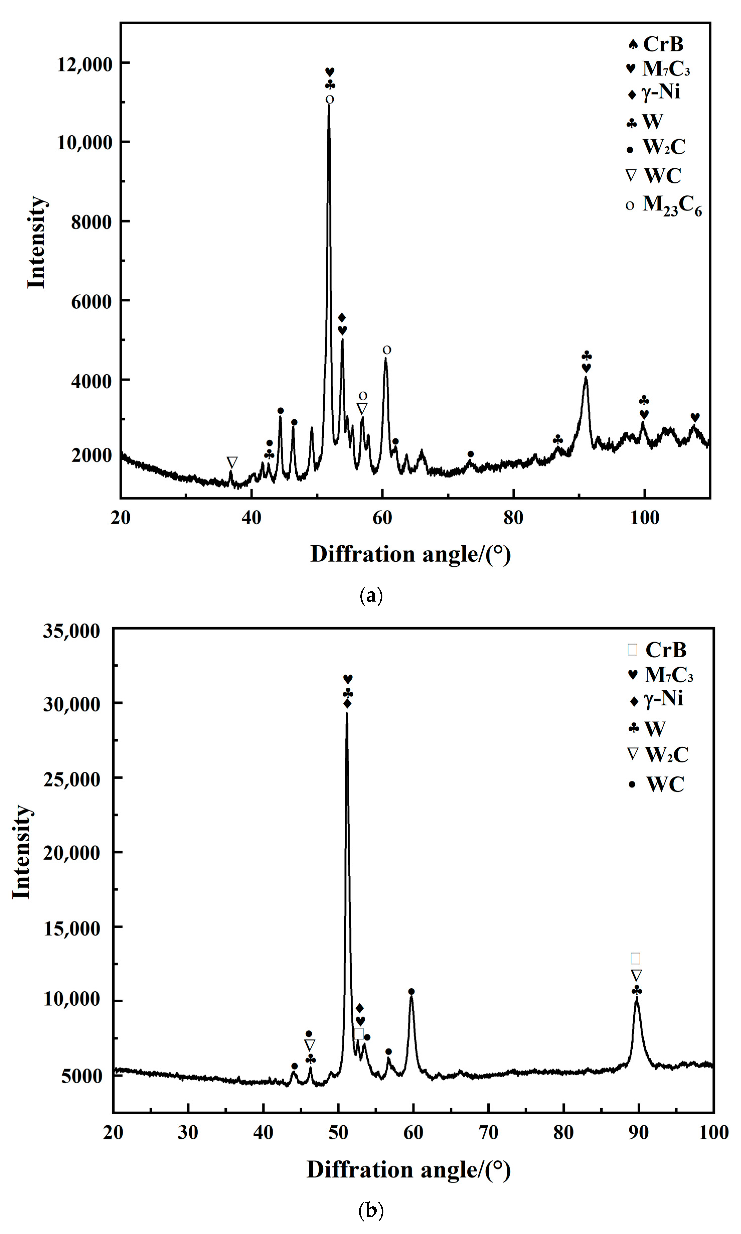
During cladding, complex reactions of physical chemistry occur and intermetallic compounds form in the Ni-based alloy with 30% WC. Figure 8 shows the XRD spectra of the cladding layers that come from Ni-based alloy with 30% WC at laser powers of 1200 and 1600 W. There were hard phases of γ-Ni, M7C3, M23C6, CrB, W, W2C, WC, etc., which increased the hardness and wear resistance of the cladding layer. With the heat effect of the laser, WC fuses and reacts with C and then forms W2C and other hard phases during cladding [18]. There were more types of hard phases in the cladding layer at the laser powers of 1200 W than that of 1600 W.
3.3. Laser Cladding Hardness Testing
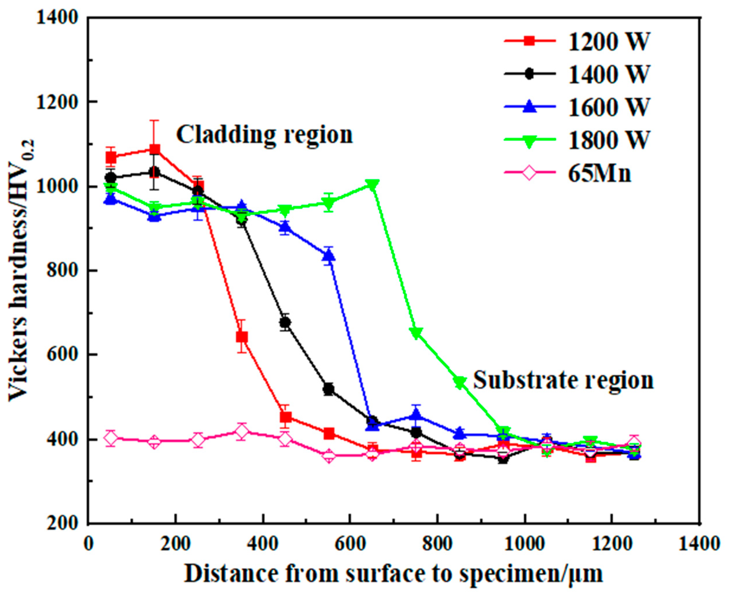
Figure 9 shows the microhardness value curve from the cladding layer to the substrate at selected laser powers. The microhardness of the cladding layers was obviously higher than that of the substrate. The average microhardness value of the cladding layer was approximately 1000 (HV0.2), and the peak value was 1100 (HV0.2). During cladding, hard carbides of WC, W2C, W3C, and CrB formed and increased the hardness of layer. This was not only related to the WC-related hard phase generated in the cladding layer [19], but also the refinement of the microstructure [20]. The dilution effect makes the atoms in the bonding area between the cladding layer and the substrate diffuse each other. Therefore, the microhardness of the bonding area was lower than that of the middle and upper parts of the cladding layer, but it was also significantly higher than that of the substrate. When the laser power increases, atom diffusion and phase transformation can improve the hardness of the materials at the substrate near the cladding layer [21].
3.4. Impact Toughness Test
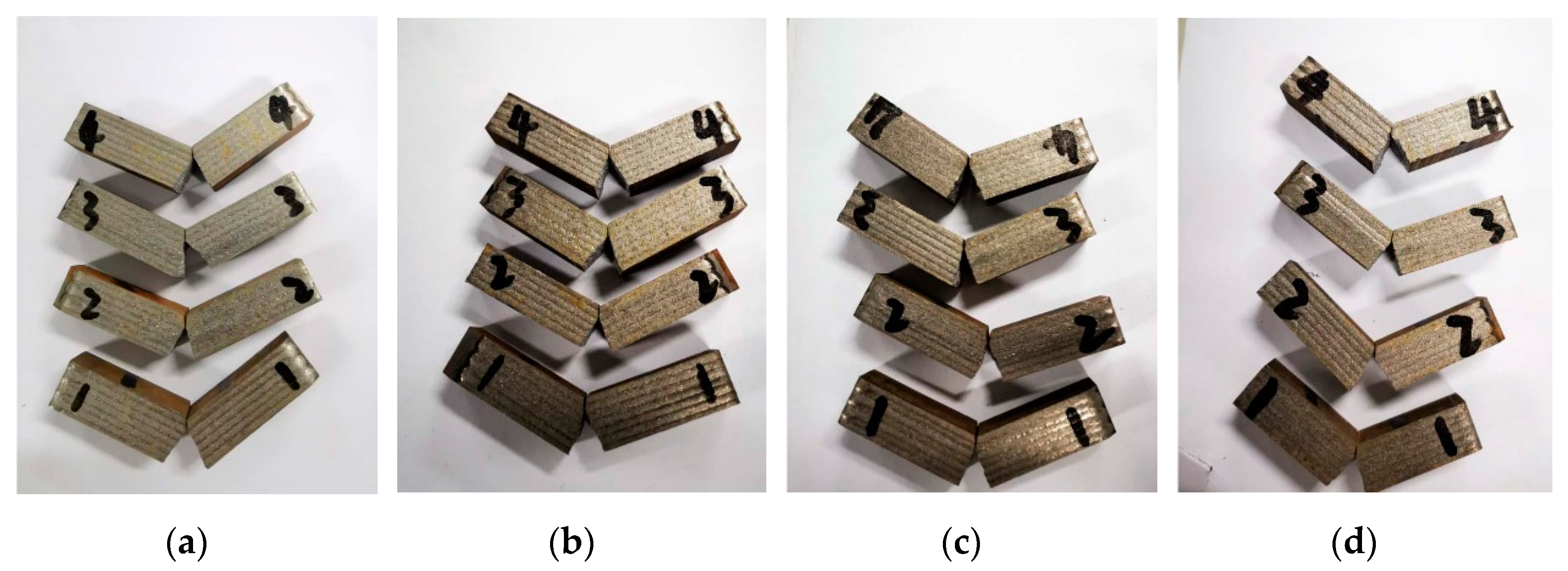
An impact test was performed at room temperature. The side of the specimens with the cladding layer was placed down according to the working position of the knives. All specimens were divided into four groups, and each group consisted of four specimens, which is shown in Figure 10. Impact absorption energy values were averaged over four specimens in one group. Impact toughness was calculated according to Equation (1) [22,23]:
where:
- ak—Impact toughness, J/cm2;
- Ak—Impact absorption energy, J;
- S—Standard fracture surface area of the impact test, cm2.
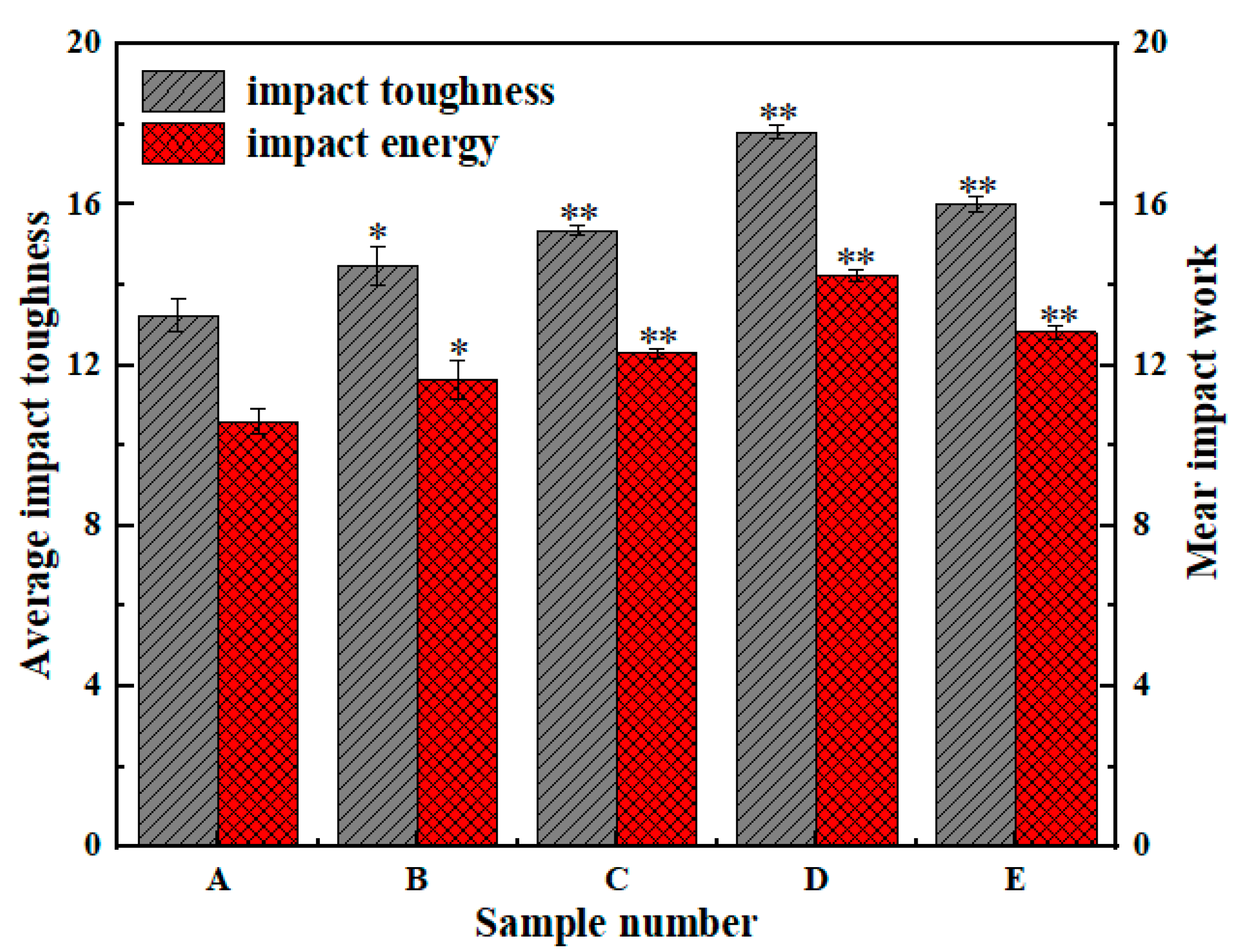
Charpy impact test results of the specimens are shown in Figure 11. The impact toughness of 65Mn steel base metal cutter was significantly affected by laser cladding, and marked** is more significant than *. Laser cladding exerts a notable effect on the impact toughness of the knives. The average impact toughness value of the specimens without cladding was 13.25 J/cm2, and the average impact toughness values of the specimens with laser cladding at the powers of 1200, 1400, 1600, and 1800 W were 14.44, 15.36, 16.82, and 16.03 J/cm2, respectively. The effect of laser cladding on the increase in the impact toughness varied with the laser power. When the laser power was 1600 W, the laser cladding increased the impact toughness of the specimens to the degree of 78.7%. Physical chemistry reactions performed inadequately at low laser powers; therefore, the toughness of the cladding layers were low. But overly high laser powers decreased the toughness of the substrate material near the interface between the coat and substrate; thus, the toughness of the specimens dd not increase with the laser power when the laser power was too high.
3.5. Wear Resistance Analysis
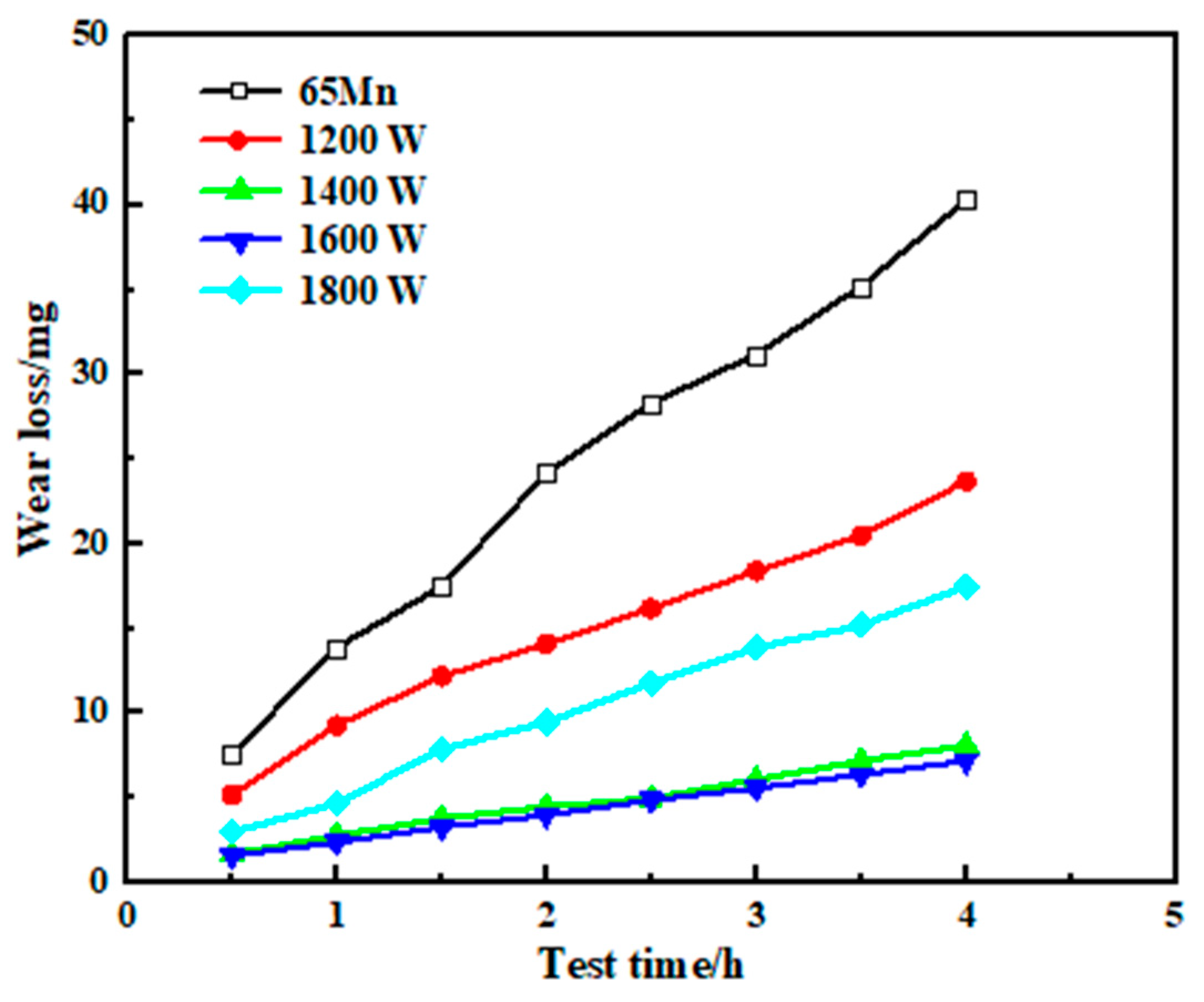
Figure 12 shows the mass loss of the substrate and cladding layer from indoor friction tests. The mass loss for the substrate due to the fact of friction was the highest for all specimens, and it had a wear rate of approximately 10.075 mg/h. The wear rates of the cladding layers were 6.025, 2.325, 2.475, and 3.200 mg/h, respectively, at the different laser powers. When the laser power was 1600 W, the wear-resisting property of the cladding layer was the best, which was 4.3 times that of the substrate.
Research by Evans and Wayne [24,25] shows that wear resistance is related with the hardness of the material. A large number of hard phases in the cladding layer increases the hardness and wear resistance of the layer material. On the other hand, impact toughness exerts a notable influence on the wear resistance of material. The formula can be concluded similar to (2):
where:
- —fracture toughness;
- H—hardness;
- C—coefficient of friction.
When the value of the laser power is between 1200 and 1800 W, a compaction layer of the Ni–WC alloy formed at the surface of the 65 Mn steel. When the laser power was 1600 W, the hardness of the cladding layer was high, and the impact toughness of the cladding layer was the highest for all of the specimens. Therefore, according to Formula (2), the combination of high hardness and high toughness leads to high wear resistance.
Figure 13 shows the abrasion morphology of the 65 Mn steel and the coat of the Ni–WC alloy using SEM. Under the same abrasive condition, the wear was severe on the surface of the 65 Mn steel. Because the hardness of the 65 Mn steel was lower, a number of scratches and ploughs parallel to the slide direction formed at the material’s surface. The wear mechanisms of the specimens was mainly abrasive wear [26]. By contrast, the scratches on the coat’s surface were shallow due to the fact of its high hardness.
4. Field Experiments on a Laser Cladding Self-Sharpening Cutter
High working speed of a rotary flail knife leads to severe abrasive wear of the knife, especially the knife point. The speed of the knife point is higher than other parts of the knife, because it is far from the rotating shaft. Therefore, the knife point is more susceptible to wear than other parts of the knife, which decreases the cutting performance of the knife point [27,28]. The self-grinding knife and 65 Mn steel knife were assembled on one rotating shaft. Figure 14 shows the macro-morphology of the two types of knives after usage for 43 h. For the integral knife made of 65 Mn steel, the wear rate of the two sides of the cutting edge was the same, and the knife point became an arc shape due to the severe wear. The cutting performance of the dull knife became poor, which increased the effects of slide, impact, and tear on the crop [29]. The wear rate of the bottom side decreased after coating with a wear-resistance layer on the bottom side of the cutting edge. The coated layer projected out from the cutting edge, which made the knife stay sharp.
Laser cladding self-grinding knives and knives without cladding were assembled on the same lawn mower. With the same working condition, the mass loss of the tested knives were recorded and are shown in Figure 15.
At the early stage of cutting, the wear rates of the knives were high. As the working time expanded, the knives underwent the normal wear process, and for which the mass loss due to the wear decreased. The mass loss of the knives with the laser cladding was obviously lower than the knives without cladding. For the knives with laser cladding, the rate of mass loss was 0.186 g/h after 76 h of cutting. By contrast, for the knives without cladding, it was 0.521 g/h for the same working time. There was a good combination between the substrate and the cladding layer with a dense micro-structure. Thus, erosion of the coat did not take place for all of the knives with laser cladding during operation. The mass loss rates were different for the knives cladded with different laser powers. The mass loss rate of the knife with cladding at 1600 W was the lowest for all of the knives. The wear resistance was related with the hardness, toughness, and quality of the cladding layer. Although the layer hardness under the laser power of 1200 W was the highest, the toughness was poor and the mass loss of the knife was still high. From a cost-effectiveness perspective, the process of laser cladding increased the cost of making the knife by thirty percent, but the life of the knife with laser cladding was more than two times longer than that of knives without laser cladding. Therefore, laser cladding increased cutting performance and decreased the cost of the knife.
5. Conclusions
- (1)
- In this study, a Ni–WC alloy layer was made at the surface of the cutting edge by laser cladding. A microstructure of typical rapid directional solidification was formed in the cladding layer that was dense and without defects such as cracks and gas holes. A metallurgical combination was formed between the substrate and cladding layer. Obvious composition dilution did not take place at the cladding layer;
- (2)
- A large number of hard phases formed during the laser cladding, increasing the hardness of the cladding layer. The chosen hardness value of the cladding layer was approximately 1100 HV(0.2), and the average hardness value was approximately 1000 HV(0.2). The hardness of the cladding layer was obviously higher than that of the substrate, but there was a good hard gradient between the cladding layer and the substrate;
- (3)
- The laser cladding increased the impact toughness of the knife to a large degree. When the laser power was 1600 W, the cladding layer had a combined high hardness and toughness and the best wear resistance. The friction mass loss of the 65 Mn steel was approximately four times that of the cladding layer;
- (4)
- Contrasting with common knives made with 65 Mn steel, a self-sharpening edge was formed during operation for the knives after laser cladding with the Ni–WC alloy. The sharp cutting edge of the laser cladding knives was still kept after usage for 76 h. The wear resistance and cutting performance increased sharply due to the laser cladding;
- (5)
- The successful manufacturing the self-grinding knife using laser cladding increased the working performance and cost effectiveness, while ensuring excellent work efficiency. The tool’s life increased by more than double, with only a 30% cost increase. This product has a large market and strong application in agricultural machinery.
Author Contributions
Conceptualization, L.X.; Data curation, M.L. and M.G.; Formal analysis, Z.S.; Funding acquisition, Z.S. and M.G.; Investigation, Z.S.; Methodology, L.X. and J.G.; Project administration, F.L.; Resources, L.X.; Supervision, J.G.; Validation, Z.S., F.L., J.G., and M.G.; Writing—original draft, L.X. and M.L.; Writing—review and editing, M.G. All authors have read and agreed to the published version of the manuscript.
Funding
This research was supported by the China National Key R&D Program during the 13th Five-Year Plan Period (grant number: 2016YFD0701701-01), the Technical Innovation Guide Plan of Shandong Province: Shandong–Chongqing Total Cooperation Project (grant number: 2020LYXZ021), and the Natural Science Foundation of Tianjin (grant number: 19JCYBJC19100).
Conflicts of Interest
The authors declare no conflict of interest.
References
- Zhang, J.B.; Wang, C.C.; Wang, Y.; Ge, Y.Y. Research on soil abrasive wear of soil touching parts of agricultural tillage machinery. J. Mod. Agric. 2015, 1, 52–53. [Google Scholar]
- Wild, K.J.; Walther, V.; Schueller, J. Optimizing Fuel Consumption and Knife Wear in a Self-Propelled Forage Chopper by Improving the Grinding Strategy. J. ASABE Annu. Int. Meet. 2009, 6, 1–18. [Google Scholar]
- Victor, A.; Warouma, A.; Lysenko, S.; Kuzyk, A. Improving of the wear resistance of working parts agricultural machinery by the implementation of the effect of self-sharpening. Int. J. Eng. Technol. 2016, 5, 126–130. [Google Scholar]
- Xu, L.F.; Tian, C.; Liu, T.; Li, F.D.; Song, Z.H.; Cao, C.M.; Yuan, H.T. Preparation of knife with self-sharp edge by laser caldding Ni-based WC composite coating. J. Agric. Eng. 2020, 10, 72–78. [Google Scholar]
- Guo, L.; Shen, Q.T. Hay cutter blade chemical heat treatment deformation strengthening research, agricultural mechanization research. J. Agric. Mech. Res. 2013, 35, 67–69 and 73. [Google Scholar]
- Hao, J.J.; Yang, Z.Y.; Ma, L.P.; Zhao, J.G.; Liu, J.C. Fe-Cr-C-V plasma surfacing layer improving wear resistance and impact toughness of rotary blade. J. J. Agric. Eng. 2019, 35, 24–30. [Google Scholar]
- Pan, Z.; Dong, X.P.; Cao, H.T.; Huang, Q.W. The Role of Distribution Forms of Fe–Cr–C Cladding Layer in the Impact Abrasive Wear Performance of Hadfield steel. J. Mater. 2020, 13, 1818. [Google Scholar] [CrossRef] [PubMed] [Green Version]
- Wang, W.; Song, Y.P.; Xu, L.F.; Gao, D.S.; Li, F.D.; Song, Z.H.; Geng, X.Y. Microstructure and hardness distribution of hardness gradient materials via vacuum composite rolling process. J. Trans. Mater. Heat Treat. 2018, 39, 87–92. [Google Scholar]
- Zhang, J.C.; Shi, S.H.; Gong, Y.Q.; Yu, S.Q.; Shi, T.; Fu, G.Y. Research Progress of Laser Cladding Technology. J. Surf. Technol. 2020, 49, 1–11. [Google Scholar]
- Rostek, T.; Homberg, W. Locally Graded Steel Materials for Self-Sharpening Cutting Blades. J. Procedia Eng. 2017, 207, 2185–2190. [Google Scholar] [CrossRef]
- Yan, L.J.; Zhang, P.X.; Wang, S.P.; Li, Z.X.; Wang, P.; Li, H.; Yang, H.Y. Microstructure and Wear Behavior of Hard Ni60 and Soft WC-12Co/Ni25 Coatings Prepared by Laser Cladding on W1813N Non-magnetic Stainless Steel. J. Rare Met. Mater. Eng. 2019, 48, 3441–3447. [Google Scholar]
- Zhang, K.; Wang, D.G.; Wang, Z.Q.; Li, Y.; Zhou, Q.; Liu, B.L.; Wang, Z.Q. Effect of Ni content and maceration metal on the microstructure and properties of WC based diamond composites. Int. J. Refract. Met. Hard Mater. 2020, 88, 105196. [Google Scholar] [CrossRef]
- LI, J.Z.; Ma, J.T.; Zhang, X.P. Effect of heat treatment process on mechanical properties of 65Mn ploughshare. Hot Work. Technol. 2017, 46, 215–217. [Google Scholar]
- Wu, P.; Du, H.M.; Chen, X.L.; Li, Z.Q.; Bai, H.L.; Jiang, E.Y. Influence of WC particle behavior on the wear resistance properties of Ni–WC composite coatings. J. Wear. 2004, 257, 142–147. [Google Scholar] [CrossRef]
- Zhang, H.M.; Hao, S.; Ma, K.X. Impact test of metal material charpy pendulum. Heavy Truck 2011, 6, 25–26. [Google Scholar]
- Wu, X.Q.; Yan, H.; Xin, Y.; Yu, B.B.; Hu, Z.; Sun, Y.H. Microstructure and Wear Properties of Ni-based Composite Coatings on Aluminum Alloy Prepared by Laser Cladding. Rare Met. Mater. Eng. 2020, 49, 2574–2582. [Google Scholar]
- He, B.; Zhuang, J.L.; Lan, J.J.; Chu, S.S. Microstructure and wear-resistance properties of tungsten carbide/cobalt-based alloys composite coating by laser cladding. J. Laser Appl. 2017, 37, 105–110. [Google Scholar]
- Wang, K.M.; Lei, Y.P.; Wei, S.Z.; Fu, H.G.; Yang, Y.W.; Li, Y.L.; Su, Z.Q. Effects of WC content on microstructure and properties of Ni based WC composite coatings for laser cladding. J. Mater. Heat Treat. 2016, 37, 172–179. [Google Scholar]
- Zhang, D.Q.; Zhang, J.Q.; Guo, Z.J. Study of the Process Parameters of Laser Cladding Ni-Based WC Powder. J. Mach. Des. Manuf. 2016, 12, 108–110. [Google Scholar]
- Lu, Q.; Zeng, X.Q.; Ding, W.J. The Hall-Petch relationship. J. Light Met. 2008, 8, 59–64. [Google Scholar]
- Cao, H.T.; Dong, X.P.; Chen, S.Q.; Dutka, M.; Pei, Y.T. Microstructure evolutions of graded high-vanadium tool steel composite coating in-situ fabricated via atmospheric plasma beam alloying. J. Alloy. Compd. 2017, 720, 169–181. [Google Scholar] [CrossRef]
- Ren, J.H.; Fu, X.Z.; FU, Y.M.; Xiang, L.; Zheng, L.J. Mechanical properties of laser cladding 45 steel composites. J. Plast. Eng. 2012, 19, 99–102. [Google Scholar]
- Lei, S.; Ren, J.M.; Shi, C.; Zhu, S.F.; Liu, N.; Chen, X. Impact Toughness and Fracture Mechanism of the Surface Laser Hardened Components of 45 Steel. J. Laser Optoelectron. Prog. 2015, 52, 011408. [Google Scholar]
- Evans, A.G.; Wilshaw, T.R. Quasi-static solid particle damage in brittle solids I. Observations, analysis and implications. J. Acta Met. 1976, 24, 939–956. [Google Scholar] [CrossRef]
- Wayne, S.F.; Buljan, S.T. Microstructure and Wear Resistance of Silicon Nitride Composites; Elsevier Press: New York, NY, USA, 1994. [Google Scholar]
- Liu, P.L.; Yang, S.Q.; Bai, L.L.; Li, Z.; Li, D.X. Wear model of disc hob cutter rings based on abrasive wear. J. China Mech. Eng. 2019, 30, 1782–1789. [Google Scholar]
- Niranatlumpong, P.; Sukhonket, C.; Nakngoenthong, J. Wear resistant surface treatment of pulverizer blades. J. Wear. 2013, 302, 878–881. [Google Scholar] [CrossRef]
- Gan, H.; Mathanker, S.; Momin, M.A.; Kuhns, B.; Stoffel, N.; Hansen, A.; Grift, T. Effects of three cutting blade designs on energy consumption during mowing-conditioning of Miscanthus Giganteus. J. Biomass Bioenergy 2018, 109, 166–171. [Google Scholar] [CrossRef]
- Song, Y.P.; Wang, Z.; Wu, K.; Li, F.D.; Song, Z.H.; Yang, X. Fabrication of Self-Sharpening Blades with Metalloceramics Materials and Low-damaged Cutting Mechanism of Alfalfa. J. Trans. Chin. Soc. Agric. Mach. 2020, 51, 309 and 421–426. [Google Scholar]
Figure 1.
(a) Macro-morphology of the silage knife after cladding; (b) cross-section morphology of the knife’s edge after cladding.
Figure 1.
(a) Macro-morphology of the silage knife after cladding; (b) cross-section morphology of the knife’s edge after cladding.

Figure 2.
(a) Laser cladding test; (b) schematic diagram of coaxial powder delivery for laser cladding.
Figure 2.
(a) Laser cladding test; (b) schematic diagram of coaxial powder delivery for laser cladding.

Figure 3.
(a) Front view of the specimen; (b) side view of the specimen.

Figure 4.
Cross-section morphology of the laser cladding sample: (a) section morphology of the 1200 W cladding layer and substrate; (b) section morphology of the 1400 W cladding layer and substrate; (c) section morphology of the 1600 W cladding layer and substrate; (d) section morphology of the 1800 W cladding layer and substrate.

Figure 5.
Metallographic structure of the cladding layer (65 Mn steel substrate): (a) microstructure of the 1200 W cladding layer and substrate; (b) microstructure of the 1400 W cladding layer and substrate; (c) microstructure of the 1600 W cladding layer and substrate; (d) microstructure of the 1800 W cladding layer and substrate.

Figure 6.
Internal microstructure of the cladding layer under different laser powers (65 Mn steel substrate): (a) 1200 W; (b) 1400 W; (c) 1600 W; (d) 1800 W.
Figure 6.
Internal microstructure of the cladding layer under different laser powers (65 Mn steel substrate): (a) 1200 W; (b) 1400 W; (c) 1600 W; (d) 1800 W.

Figure 7.
Microstructure of the coating and substrate (65 Mn steel substrate): (a) 1200 W SEM image and elemental analysis; (b) 1600 W SEM image and elemental analysis.
Figure 7.
Microstructure of the coating and substrate (65 Mn steel substrate): (a) 1200 W SEM image and elemental analysis; (b) 1600 W SEM image and elemental analysis.

Figure 8.
XRD spectra of the cladding layer: (a) 1200 W; (b) 1600 W.

Figure 9.
Microhardness distribution curve of the cladding layer at different laser powers (65 Mn steel substrate).
Figure 9.
Microhardness distribution curve of the cladding layer at different laser powers (65 Mn steel substrate).

Figure 10.
Charpy impact test of the laser cladding sample: (a) 1200 W; (b) 1400 W; (c) 1600 W; (d) 1800 W.
Figure 10.
Charpy impact test of the laser cladding sample: (a) 1200 W; (b) 1400 W; (c) 1600 W; (d) 1800 W.

Figure 11.
Charpy impact tests: (A) 65 Mn; (B) 1200 W; (C) 1400 W; (D) 1600 W; (E) 1800 W.

Figure 12.
Contrast of the wear loss of the specimen.

Figure 13.
Wear sample morphology: (a) 65 Mn sample; (b) 1600 W coated sample.

Figure 14.
Macro-morphology of the two blades after working on the harvester for 43 h of operation: (a) knife with 1600 W laser cladding; (b) 65 Mn cutting tools available on the market.
Figure 14.
Macro-morphology of the two blades after working on the harvester for 43 h of operation: (a) knife with 1600 W laser cladding; (b) 65 Mn cutting tools available on the market.

Figure 15.
Comparison of the wear loss in the field tests.


Table 1.
Chemical composition of the knife and nickel alloy.
| Material | C | Si | Cr | Mn | S | P | Ni | Fe | B |
|---|---|---|---|---|---|---|---|---|---|
| 65 Mn knife (wt%) | 0.64 | 0.23 | 0.23 | 1.15 | 0.028 | 0.032 | 0.15 | ||
| Nickle alloy (wt%) | 0.4 | 4 | 15 | 69.4 | 8 | 3.2 |
Publisher’s Note: MDPI stays neutral with regard to jurisdictional claims in published maps and institutional affiliations. |
© 2021 by the authors. Licensee MDPI, Basel, Switzerland. This article is an open access article distributed under the terms and conditions of the Creative Commons Attribution (CC BY) license (https://creativecommons.org/licenses/by/4.0/).
Share and Cite
MDPI and ACS Style
Xu, L.; Song, Z.; Li, M.; Li, F.; Guo, J.; Gao, M. Self-Grinding Silage Knife Strengthened with Ni–WC Alloy Prepared by Laser Cladding. Appl. Sci. 2021, 11, 10236. https://0-doi-org.brum.beds.ac.uk/10.3390/app112110236
AMA Style
Xu L, Song Z, Li M, Li F, Guo J, Gao M. Self-Grinding Silage Knife Strengthened with Ni–WC Alloy Prepared by Laser Cladding. Applied Sciences. 2021; 11(21):10236. https://0-doi-org.brum.beds.ac.uk/10.3390/app112110236
Chicago/Turabian StyleXu, Lingfeng, Zhanhua Song, Mingxiang Li, Fade Li, Jing Guo, and Ming Gao. 2021. "Self-Grinding Silage Knife Strengthened with Ni–WC Alloy Prepared by Laser Cladding" Applied Sciences 11, no. 21: 10236. https://0-doi-org.brum.beds.ac.uk/10.3390/app112110236
Note that from the first issue of 2016, this journal uses article numbers instead of page numbers. See further details here.