
Experimental Evaluation of the Bending Behavior of a Drilled Shaft with Partial Casing under Lateral Loads

 ,
,
Abstract
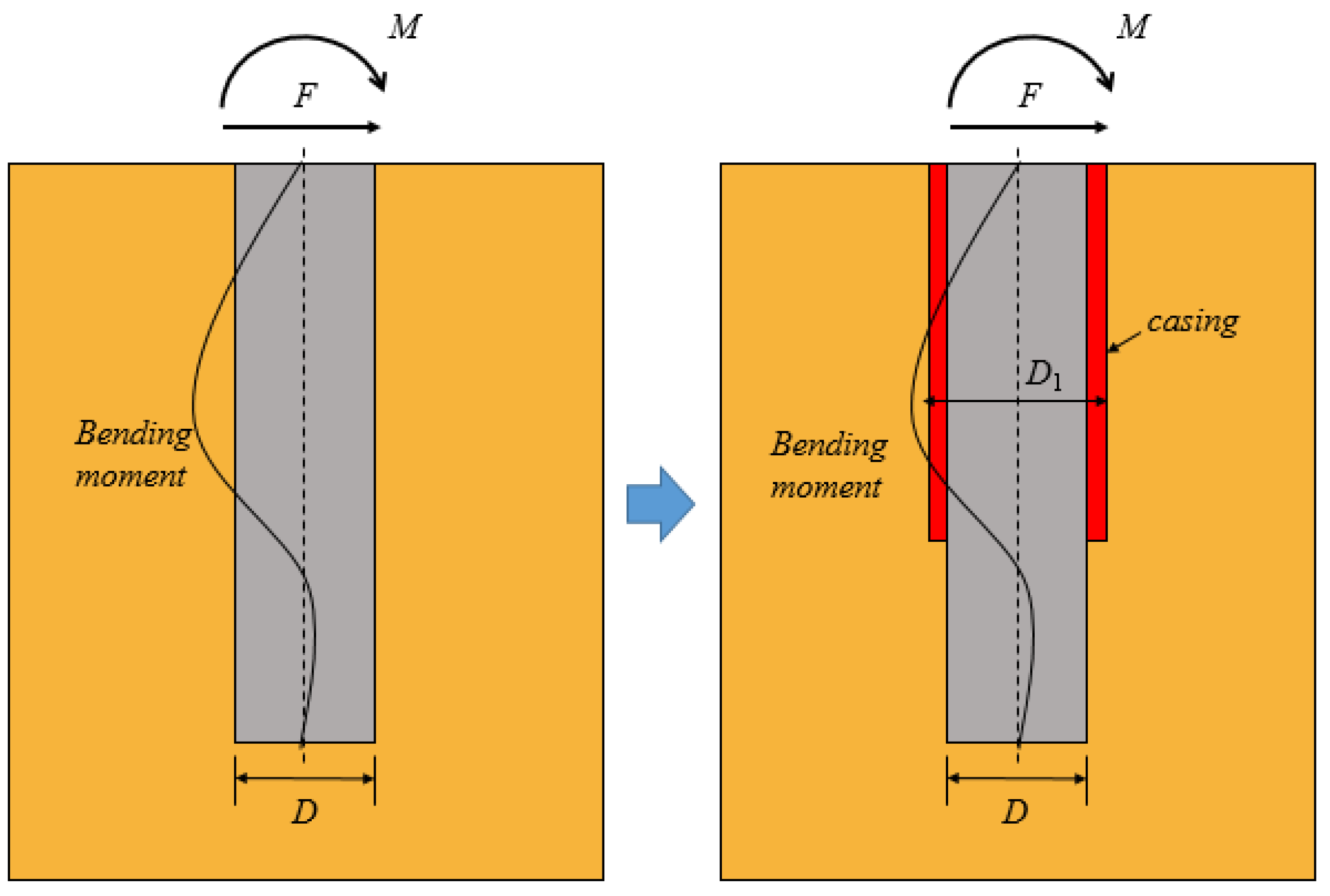
:1. Introduction
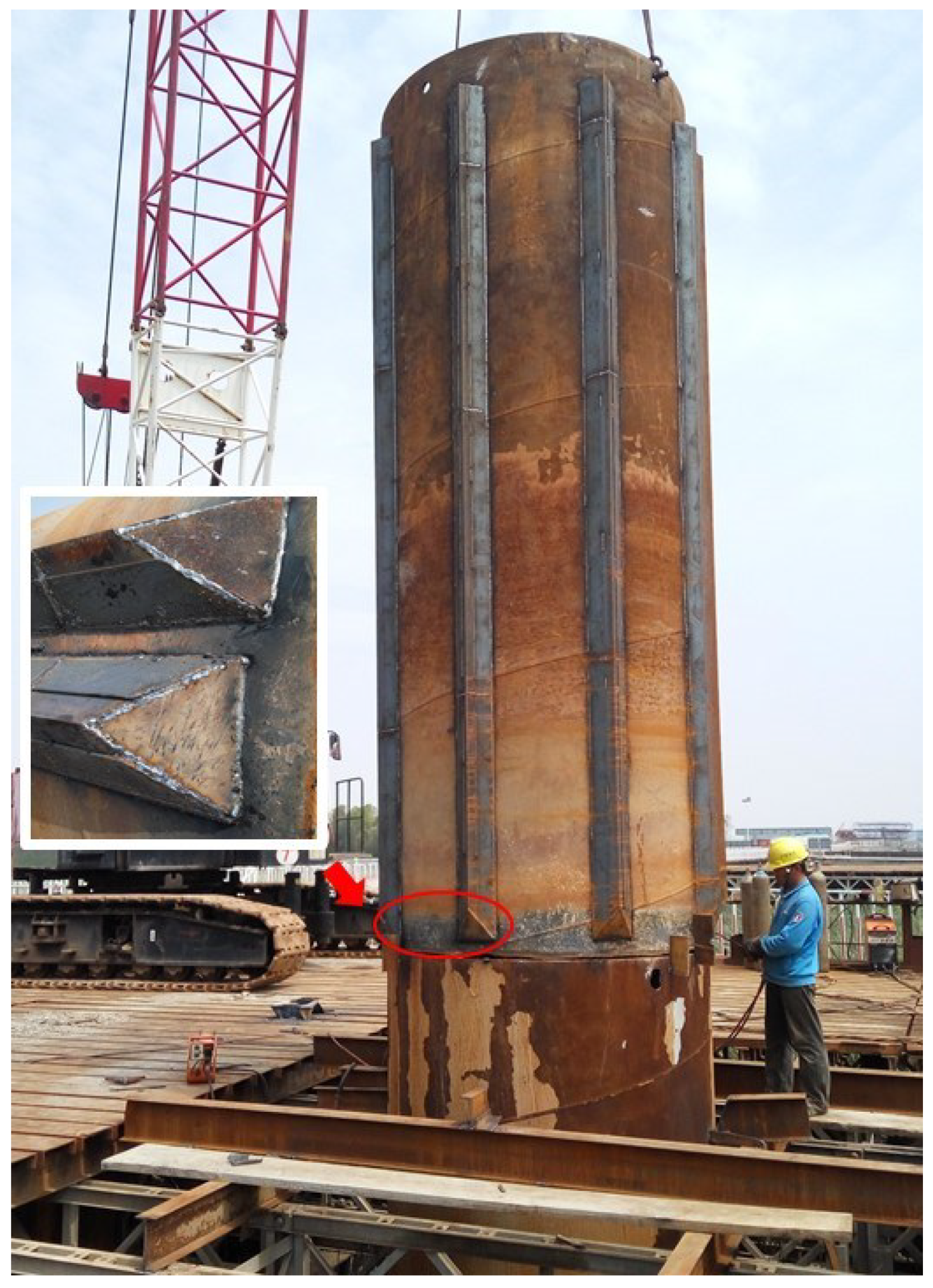
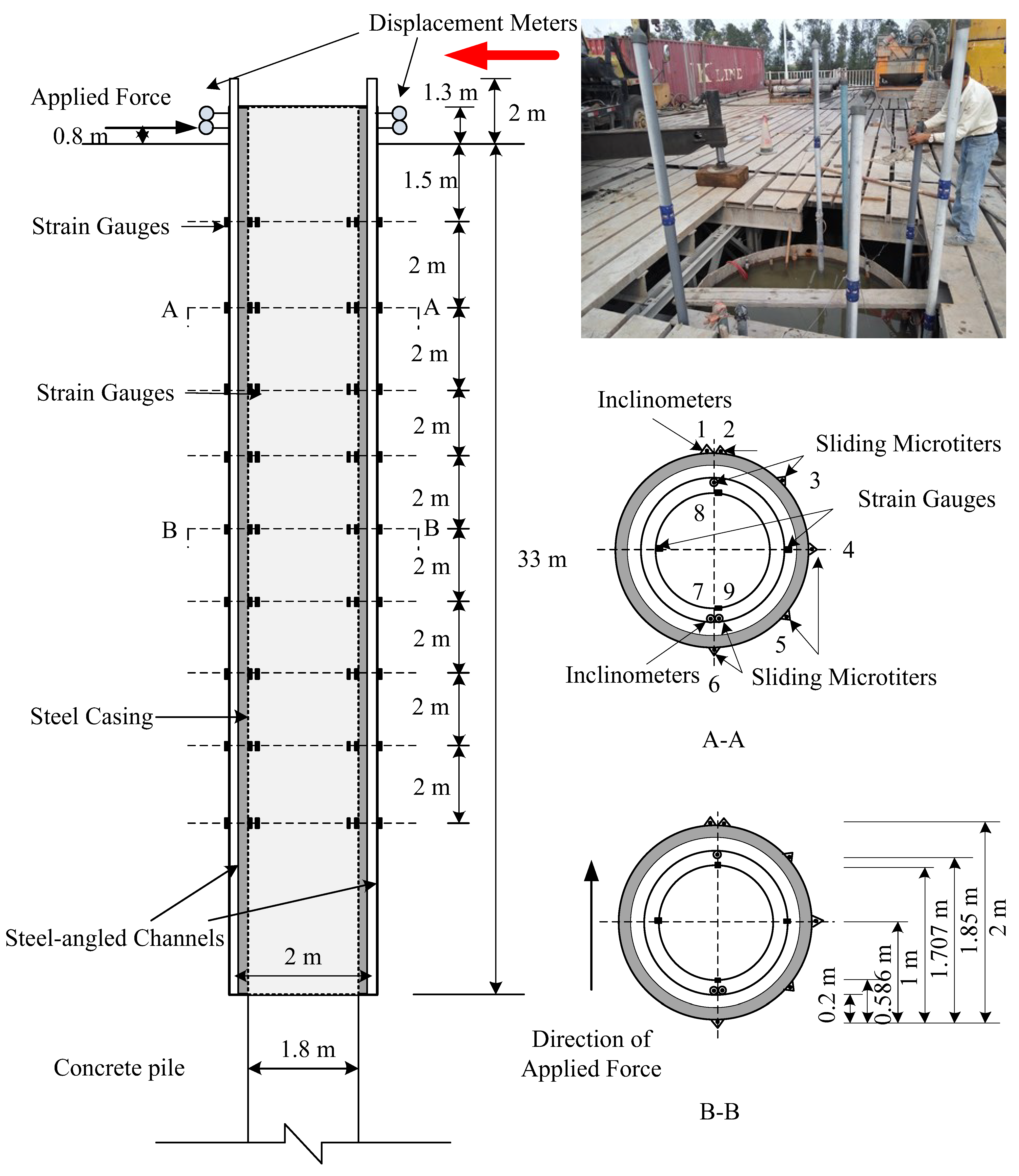
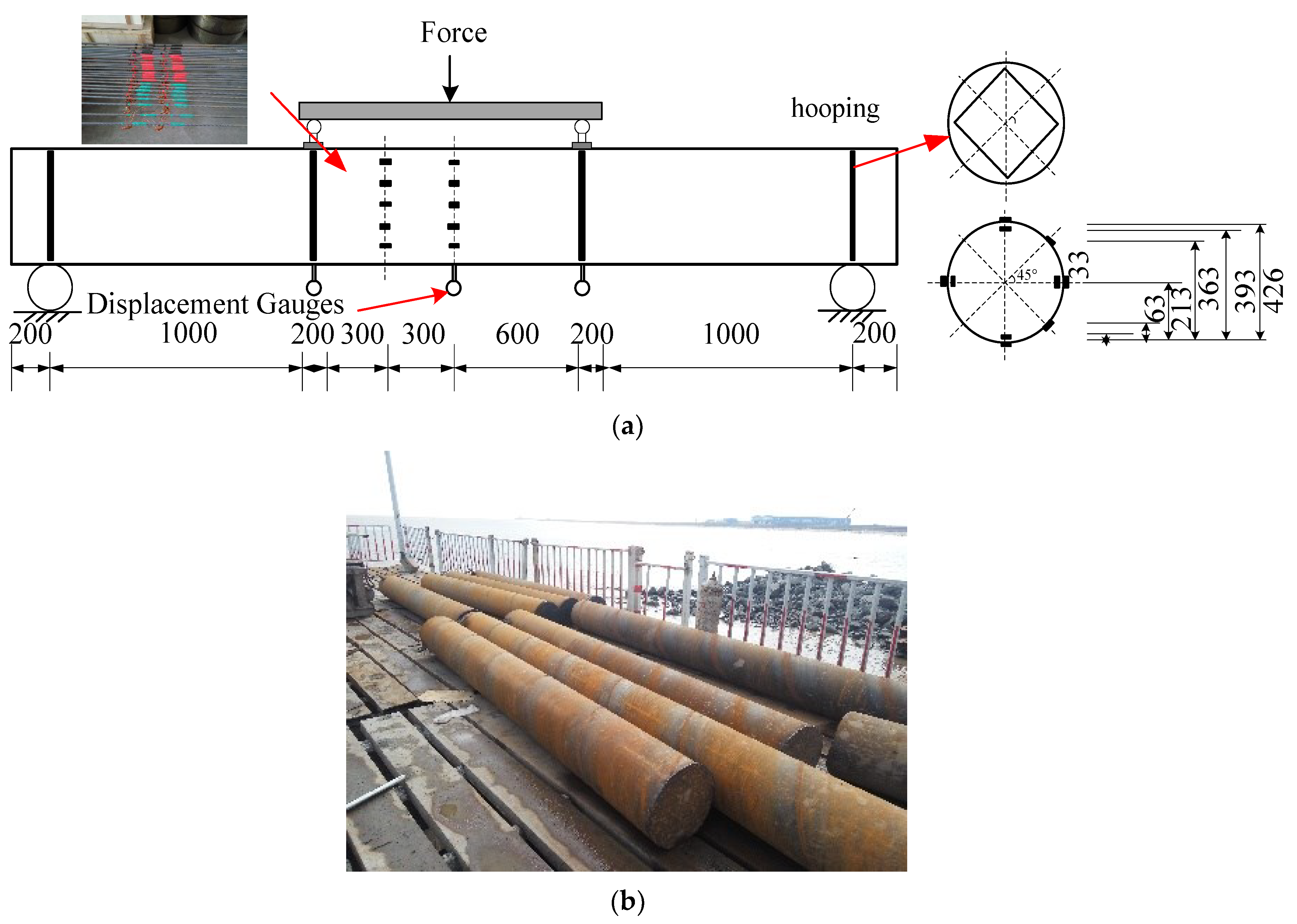
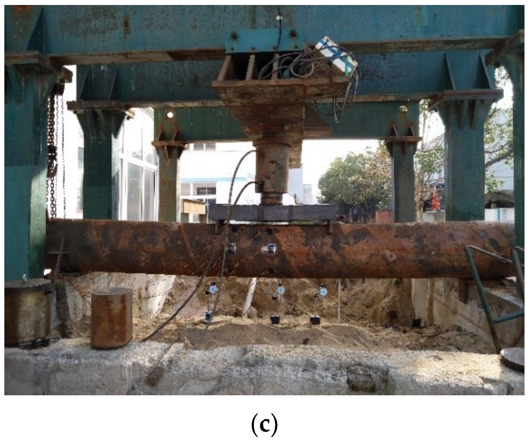
2. Experimental Program for Field Tests
2.1. Experimental Procedure
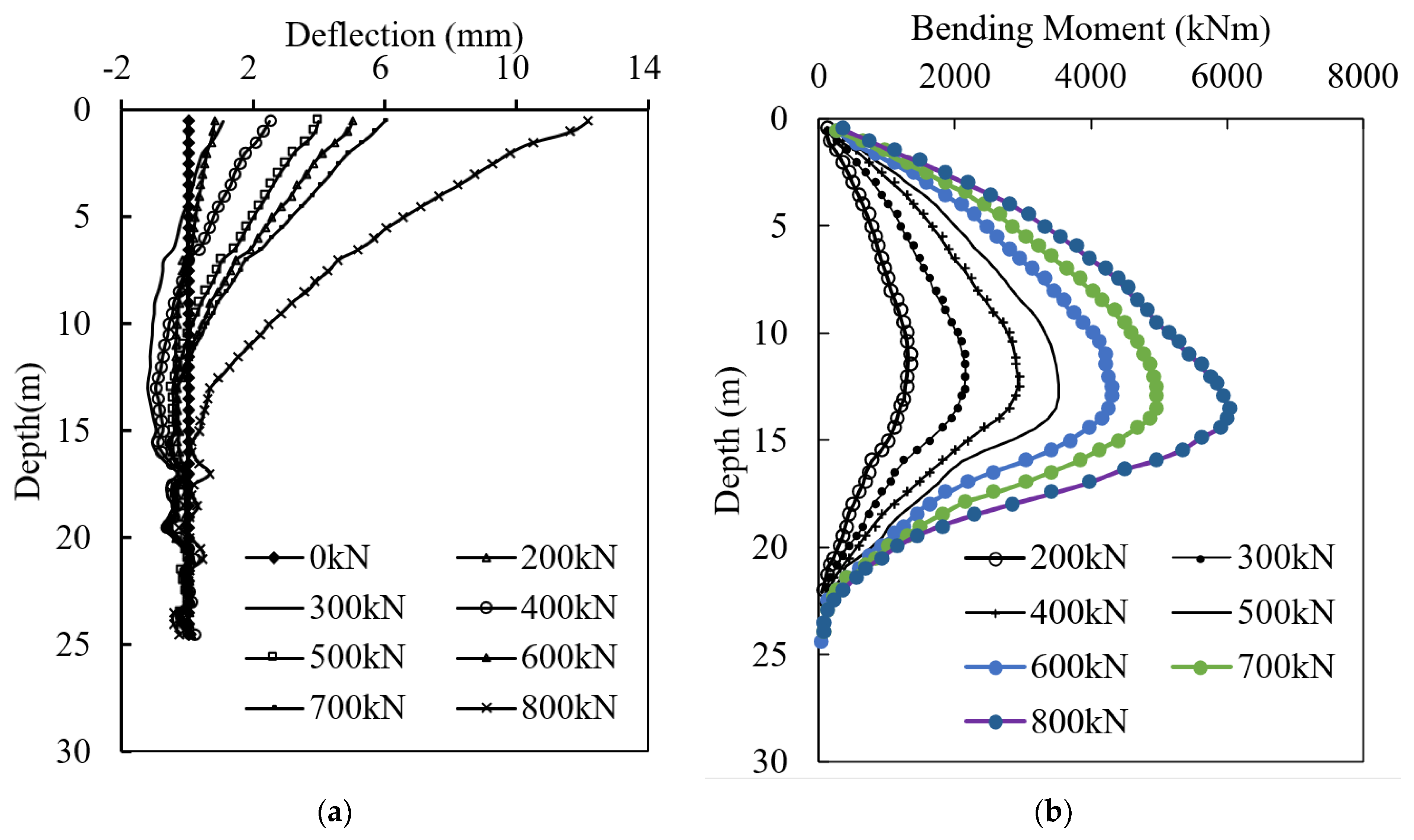
2.2. Test Results
3. Laboratory Tests
3.1. Experimental Procedure
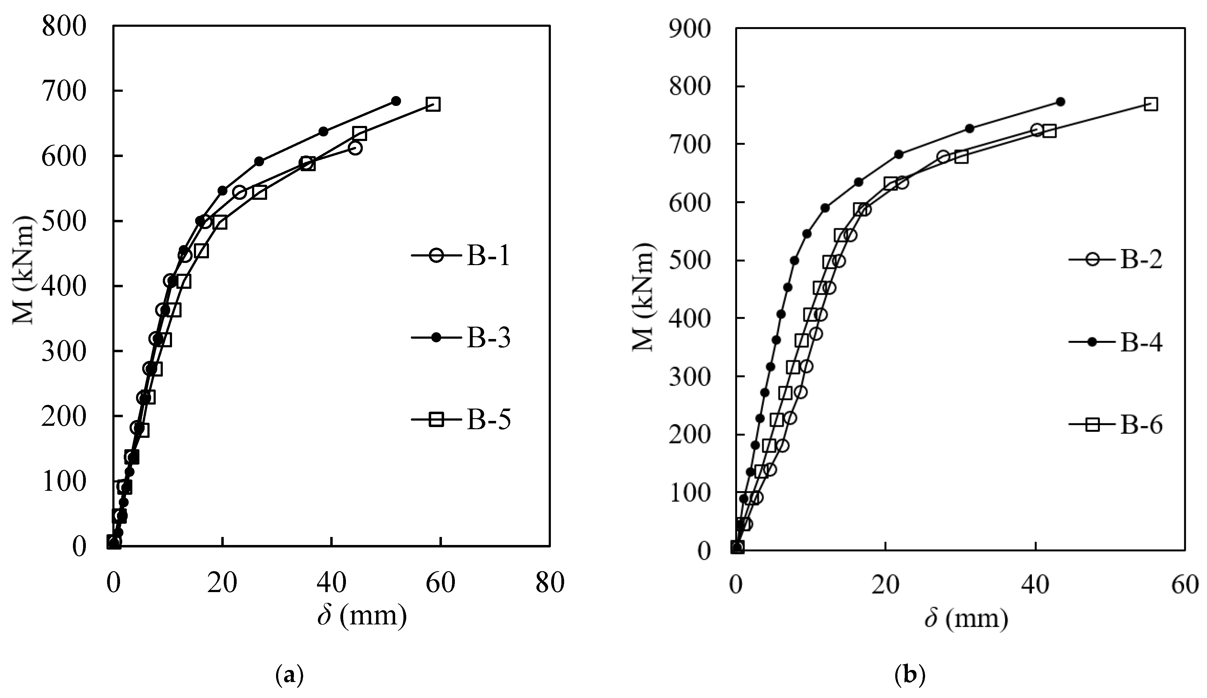
3.2. Test Results
3.3. Effects of Different Parameters on the Bending Behaviour
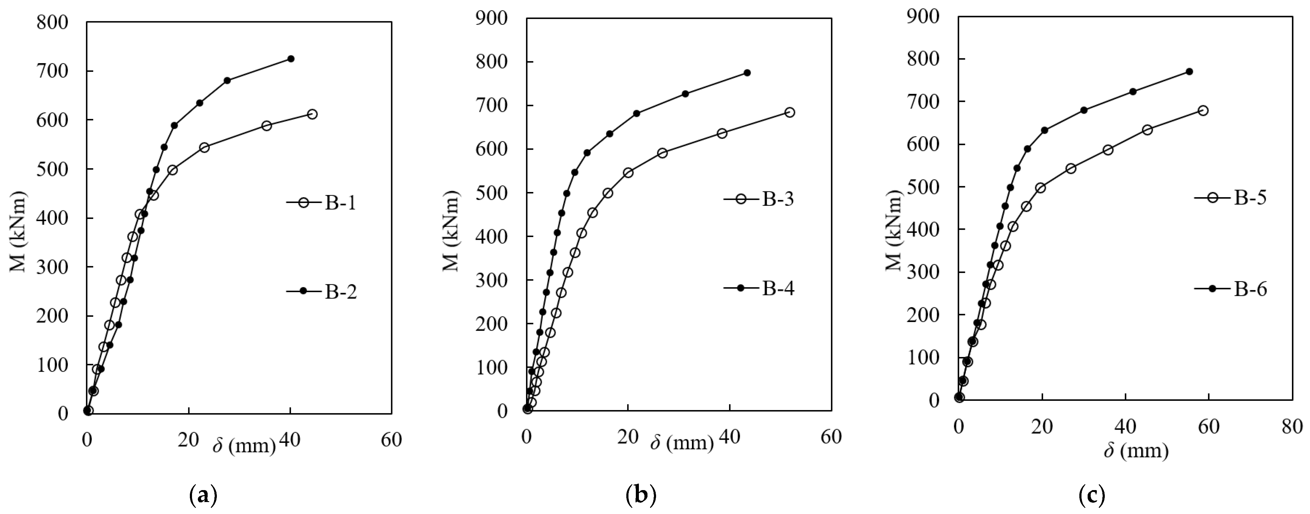
3.3.1. Effect of the Bond Quality
3.3.2. Effect of the Casing Thickness
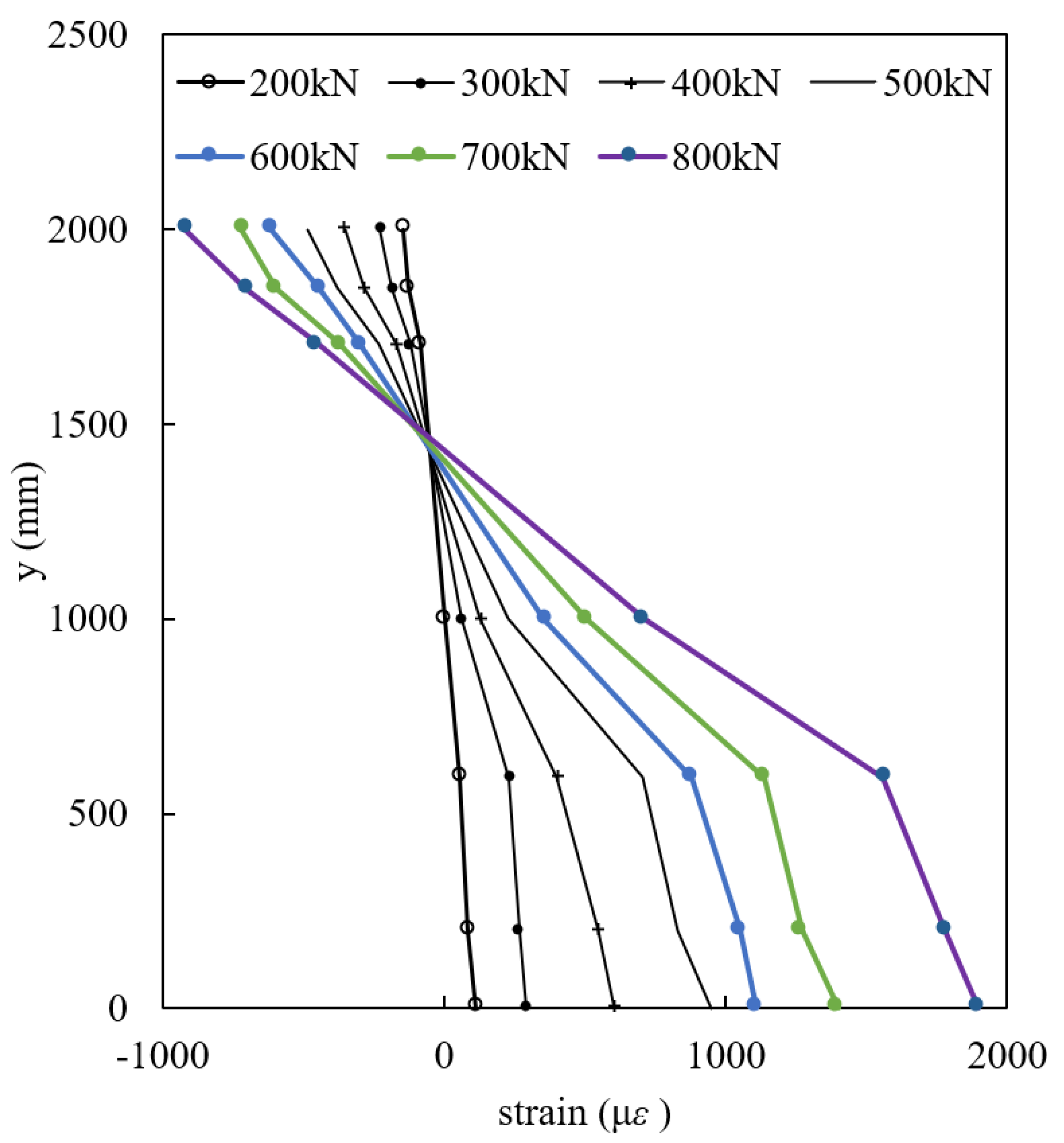
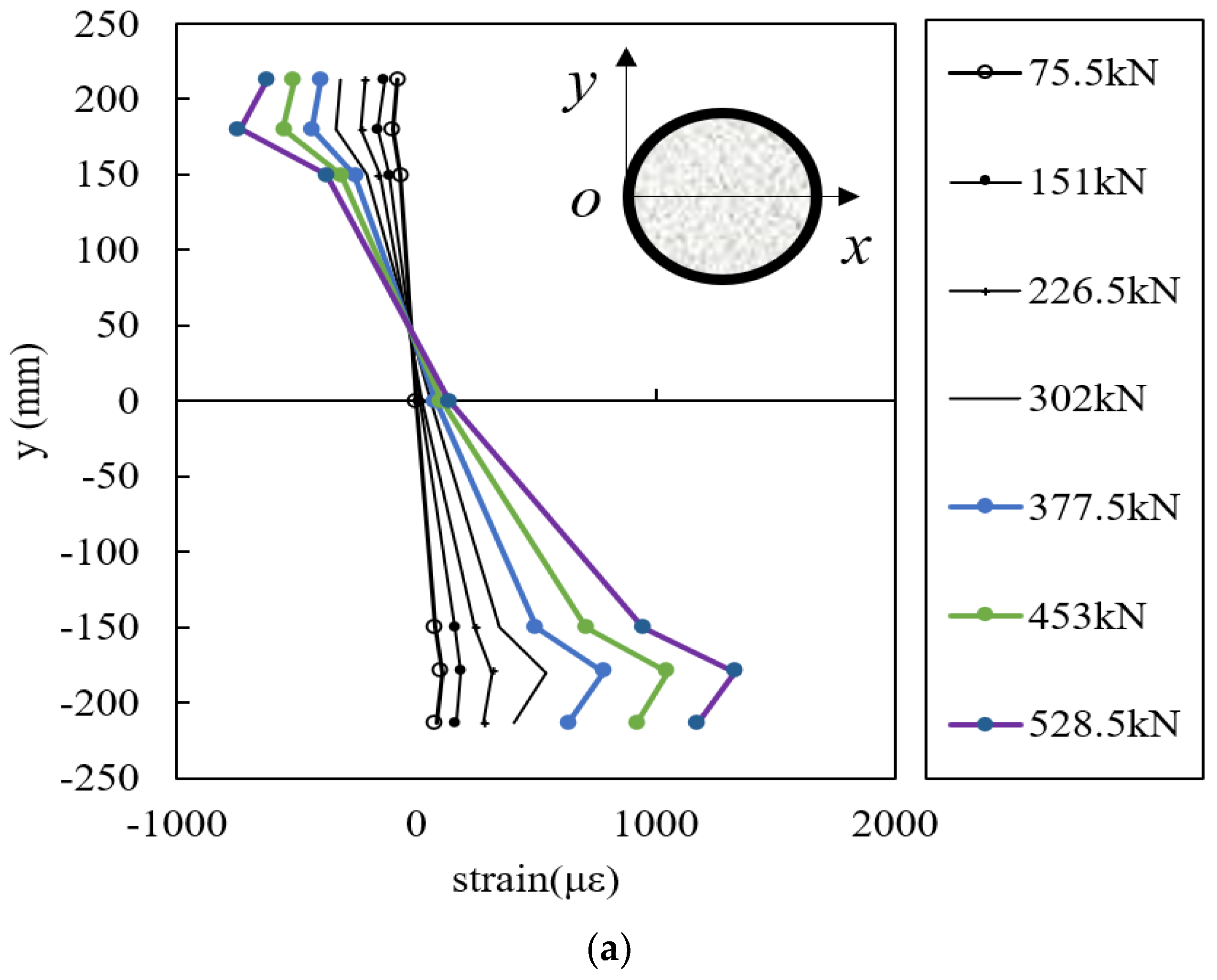
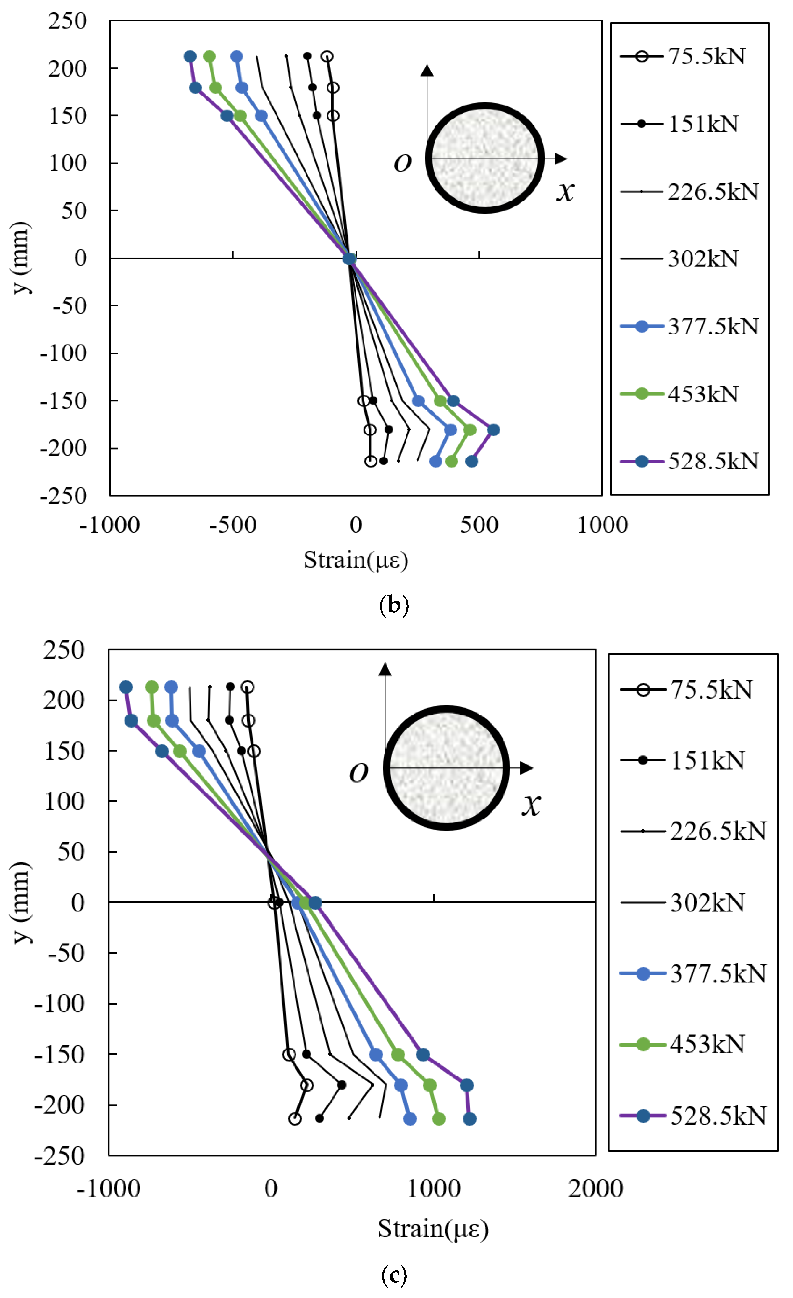
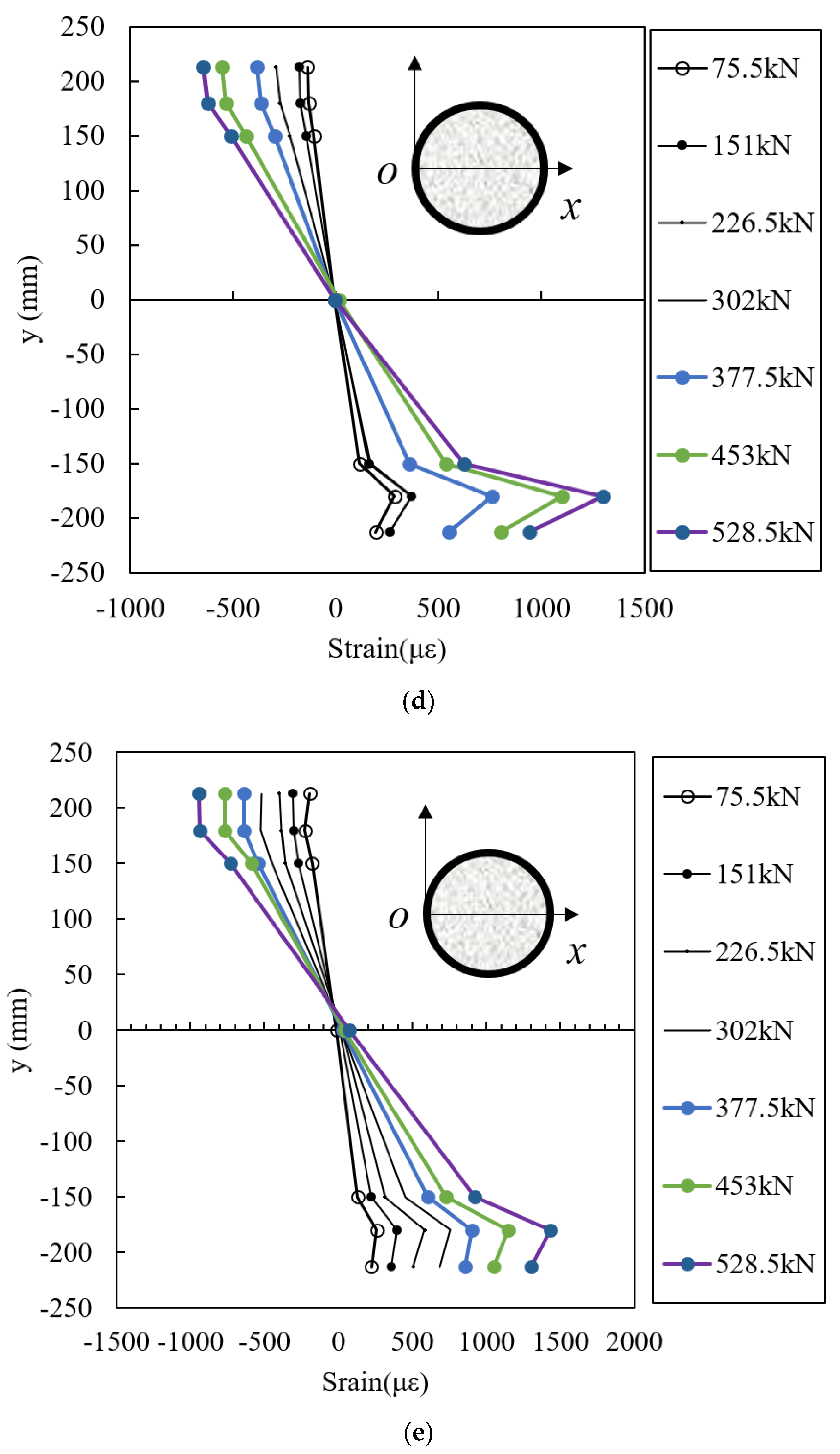
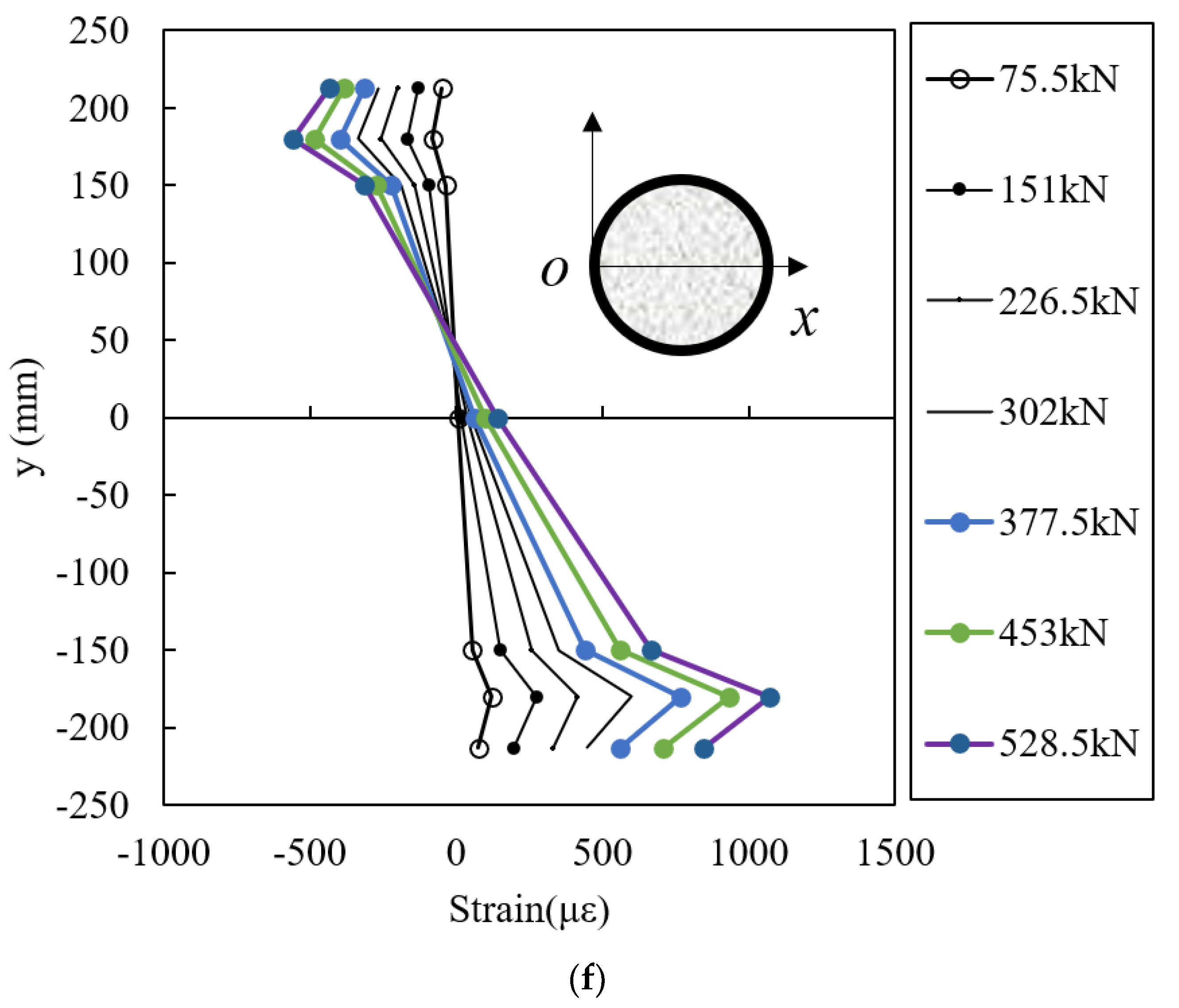
3.4. Strain along the Pile Section
4. Conclusions
- (1).
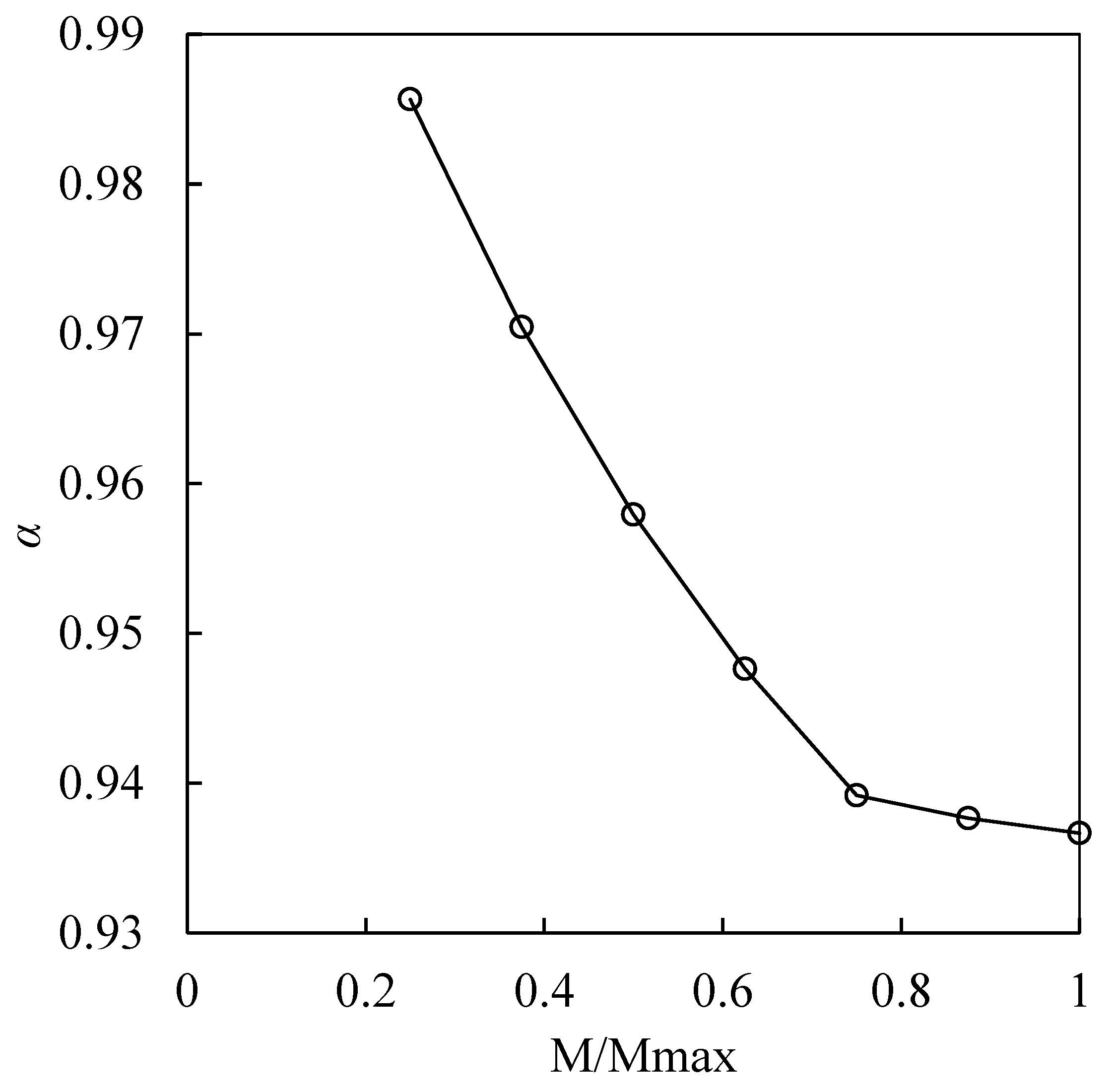
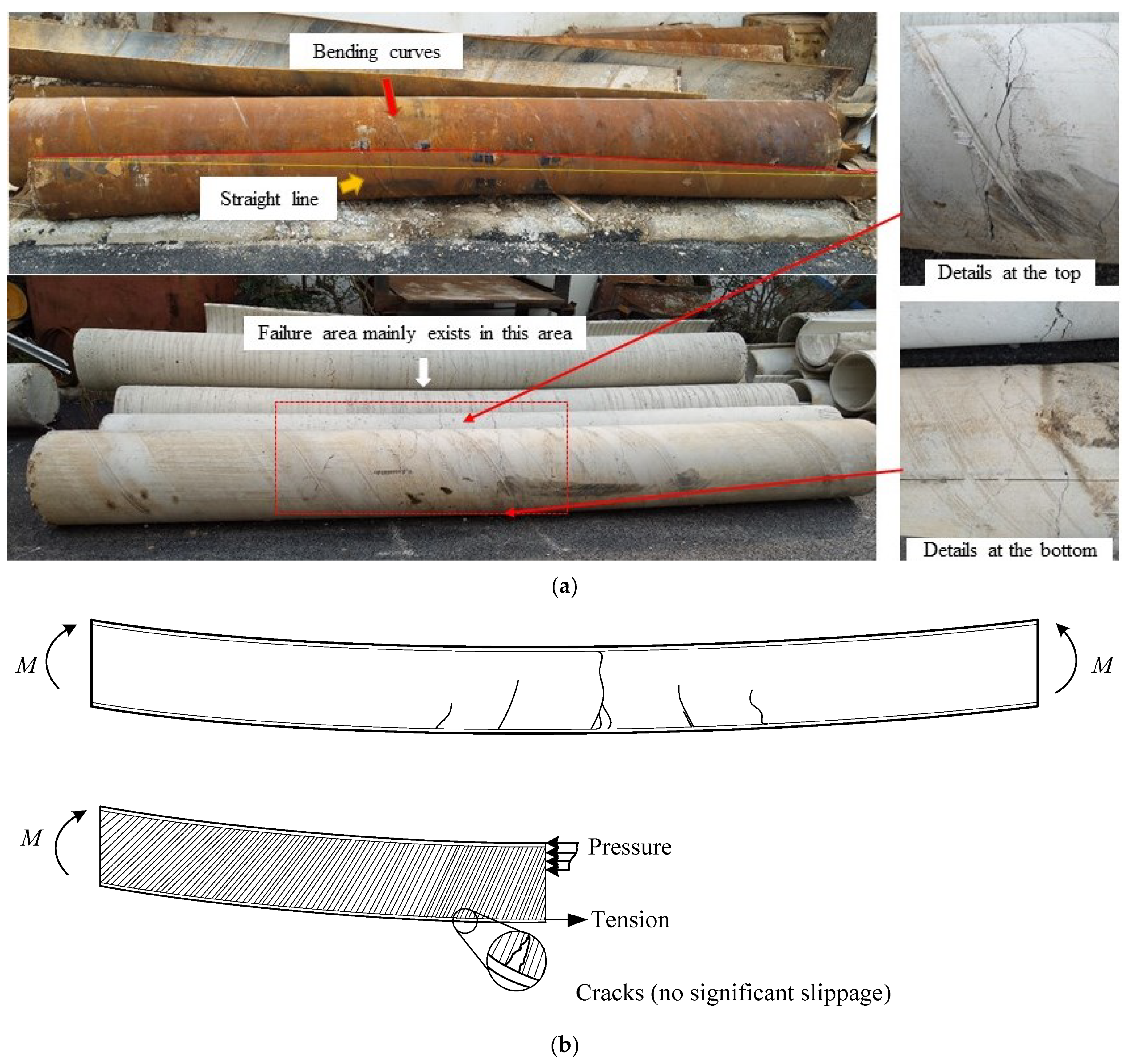
- In the field test, with the increase of the loads, there was no relative displacement between the concrete and the casing, and the casing and the concrete body of the pile deformed as an assembly. Therefore, it was suitable to use the plane cross-section assumption in the calculation. However, a correction coefficient that related to the loading level needed to be considered in the calculation of the bending stiffness.
- (2).
- From the laboratory studies, the bending capacities of those specimens were similar, the slurry condition had limited influence on the moment capacity of the specimens in terms of elastic stiffness and ductility, and the slurry condition had a negative influence on the bond quality. The plane cross-section assumption was reasonable to use in the calculation of bending capacity at low bending moments, and the influence of the casing thickness should be considered in the calculation of the section stiffness of DSPCs.
Author Contributions
Funding
Institutional Review Board Statement
Informed Consent Statement
Data Availability Statement
Conflicts of Interest
References
- Lacki, P.; Derlatka, A.; Kasza, P. Comparison of steel-concrete composite column and steel column. Compos. Struct. 2018, 202, 82–88. [Google Scholar] [CrossRef]
- Tao, Z.; Song, T.-Y.; Uy, B.; Han, L.-H. Bond behavior in concrete-filled steel tubes. J. Constr. Steel Res. 2016, 120, 81–93. [Google Scholar] [CrossRef]
- Yuan, H.; Dang, J.; Aoki, T. Behavior of partially concrete-filled steel tube bridge piers under bi-directional seismic excitations. J. Constr. Steel Res. 2014, 93, 44–54. [Google Scholar] [CrossRef]
- Chen, Y.; Feng, R.; Shao, Y.; Zhang, X. Bond-slip behaviour of concrete-filled stainless steel circular hollow section tubes. J. Constr. Steel Res. 2017, 130, 248–263. [Google Scholar] [CrossRef]
- Lyu, W.-Q.; Han, L.-H. Investigation on bond strength between recycled aggregate concrete (RAC) and steel tube in RAC-filled steel tubes. J. Constr. Steel Res. 2019, 155, 438–459. [Google Scholar] [CrossRef]
- Prion, H.G.L.; Boehme, J. Beam-column behaviour of steel tubes filled with high strength concrete. Can. J. Civ. Eng. 1994, 21, 207–218. [Google Scholar] [CrossRef]
- Virdi, K.S.; Dowling, P.J. Bond Strength in Concrete Filled Circular Steel Tube; R. CESLIC Report CC11; Department of Civil Engineering, Imperial College: London, UK, 1975. [Google Scholar]
- Wang, Z.-B.; Tao, Z.; Han, L.-H.; Uy, B.; Lam, D.; Kang, W.H. Strength, stiffness and ductility of concrete-filled steel columns under axial compression. Eng. Struct. 2017, 135, 209–221. [Google Scholar] [CrossRef] [Green Version]
- Chen, W.F. Behaviour of concrete-filled steel tubular columns. In Proceedings of the International Conference on Tall Buildings, American Society of Civil Engineers and International Association for Bridge and Structural Engineering, Bethlehem, PA, USA, 21–26 August 1972; pp. 608–612. [Google Scholar]
- Chen, W.F.; Atsuta, T. Theory of beam-columns. In Volume I: In-Plane Behaviour and Design; McGraw-Hill: New York, NY, USA, 1976; pp. 413–417. [Google Scholar]
- Chen, W.; Chen, C. Analysis of concrete-filled steel tubular beam-columns. Mem. Int. Assoc. Bridge Struct. Eng. 1973, 33, 37–52. [Google Scholar] [CrossRef]
- Nezamian, A.; Al-Mahaidi, R.; Grundy, P. Bond strength of concrete plugs embedded in tubular steel piles under cyclic loading. Can. J. Civ. Eng. 2006, 33, 111–125. [Google Scholar] [CrossRef]
- GB 50936-2014. Technical Code for Concrete Filled Steel Tubular Structures; MOHURD: Beijing, China, 2014.
- AIJ-2009. Recommendations for Design and Construction of Concrete Filled Steel Tubular Structures; Architectural Institute of Japan: Tokyo, Japan, 2009. [Google Scholar]
- Eurocode 4 (EC4). Design of steel and concrete structures. In Part 1 1: General Rules and Rules for Building; European Committee for Standardization: Brussels, Belgium, 2004. [Google Scholar]


| Material Type | Modulus of Elasticity E/GPa | Poisson’s Ratio ν | Yield Strength fy/MPa | Tensile Strength fu/MPa |
|---|---|---|---|---|
| Q235b | 210 | 0.286 | 235 | 412 |
| Specimen ID | Diameter (D/mm) | Thickness (t/mm) | Length (L/mm) | D/t | Mud Skin Condition |
|---|---|---|---|---|---|
| B-1 | 426 | 5 | 4000 | 85.2 | no |
| B-2 | 426 | 10 | 4000 | 42.6 | no |
| B-3 | 426 | 5 | 4000 | 85.2 | thin |
| B-4 | 426 | 10 | 4000 | 42.6 | thin |
| B-5 | 426 | 5 | 4000 | 85.2 | thick |
| B-6 | 426 | 10 | 4000 | 42.6 | thick |
Publisher’s Note: MDPI stays neutral with regard to jurisdictional claims in published maps and institutional affiliations. |
© 2021 by the authors. Licensee MDPI, Basel, Switzerland. This article is an open access article distributed under the terms and conditions of the Creative Commons Attribution (CC BY) license (https://creativecommons.org/licenses/by/4.0/).
Share and Cite
Li, X.; Dai, G.; Yang, X.; Yin, Q.; Zhu, W.; Zhang, F. Experimental Evaluation of the Bending Behavior of a Drilled Shaft with Partial Casing under Lateral Loads. Appl. Sci. 2021, 11, 9469. https://0-doi-org.brum.beds.ac.uk/10.3390/app11209469
Li X, Dai G, Yang X, Yin Q, Zhu W, Zhang F. Experimental Evaluation of the Bending Behavior of a Drilled Shaft with Partial Casing under Lateral Loads. Applied Sciences. 2021; 11(20):9469. https://0-doi-org.brum.beds.ac.uk/10.3390/app11209469
Chicago/Turabian StyleLi, Xiaojuan, Guoliang Dai, Xueying Yang, Qian Yin, Wenbo Zhu, and Fan Zhang. 2021. "Experimental Evaluation of the Bending Behavior of a Drilled Shaft with Partial Casing under Lateral Loads" Applied Sciences 11, no. 20: 9469. https://0-doi-org.brum.beds.ac.uk/10.3390/app11209469