
Compact Broadband Antenna with Vicsek Fractal Slots for WLAN and WiMAX Applications

 ,
,  ,
,  ,
,  and
and 
Abstract
:1. Introduction
2. Antenna Geometry Design
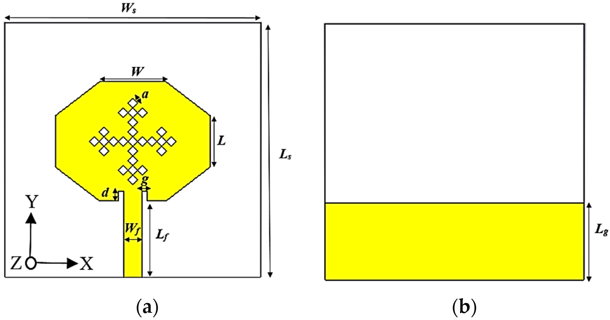
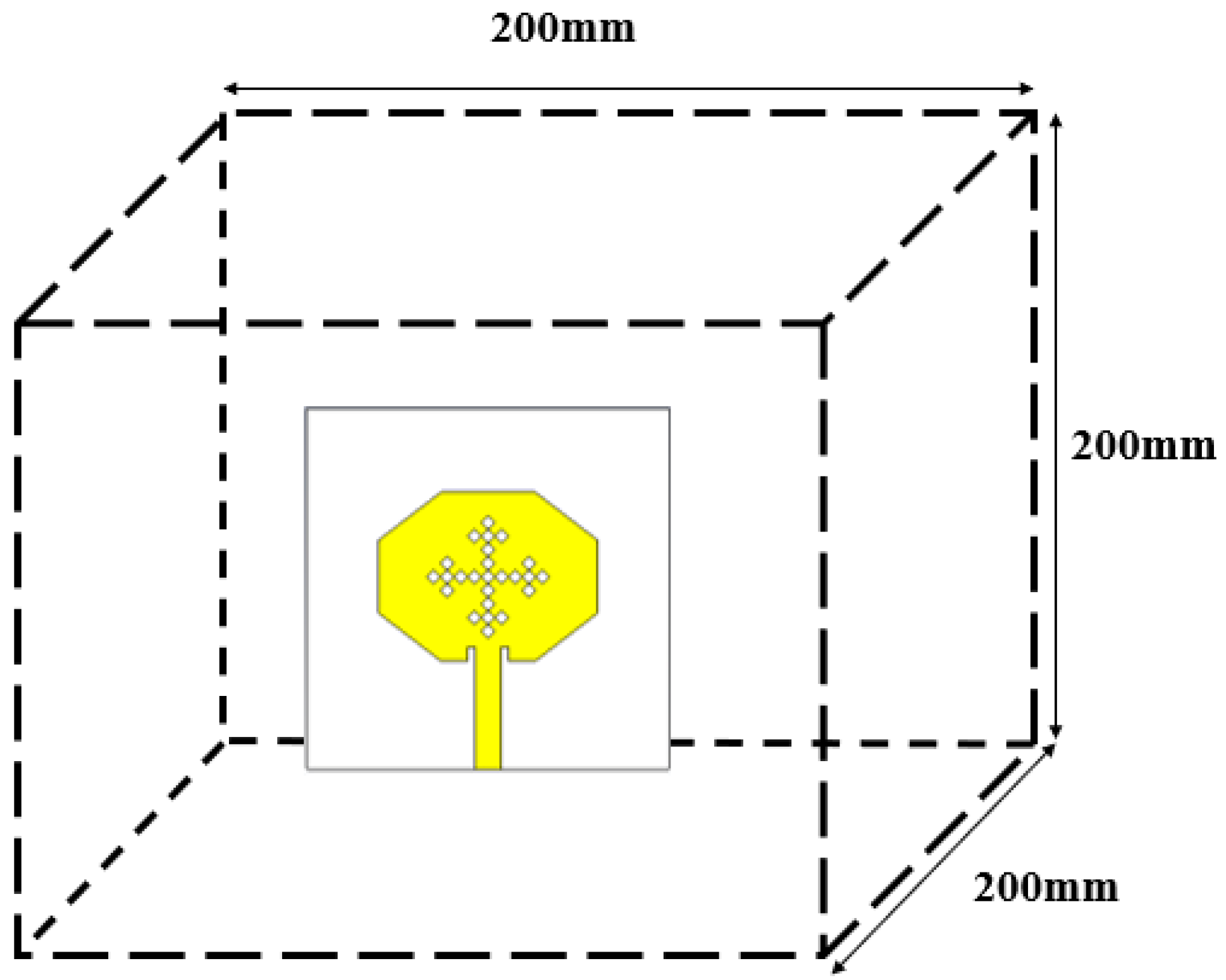
2.1. Antenna Geometry
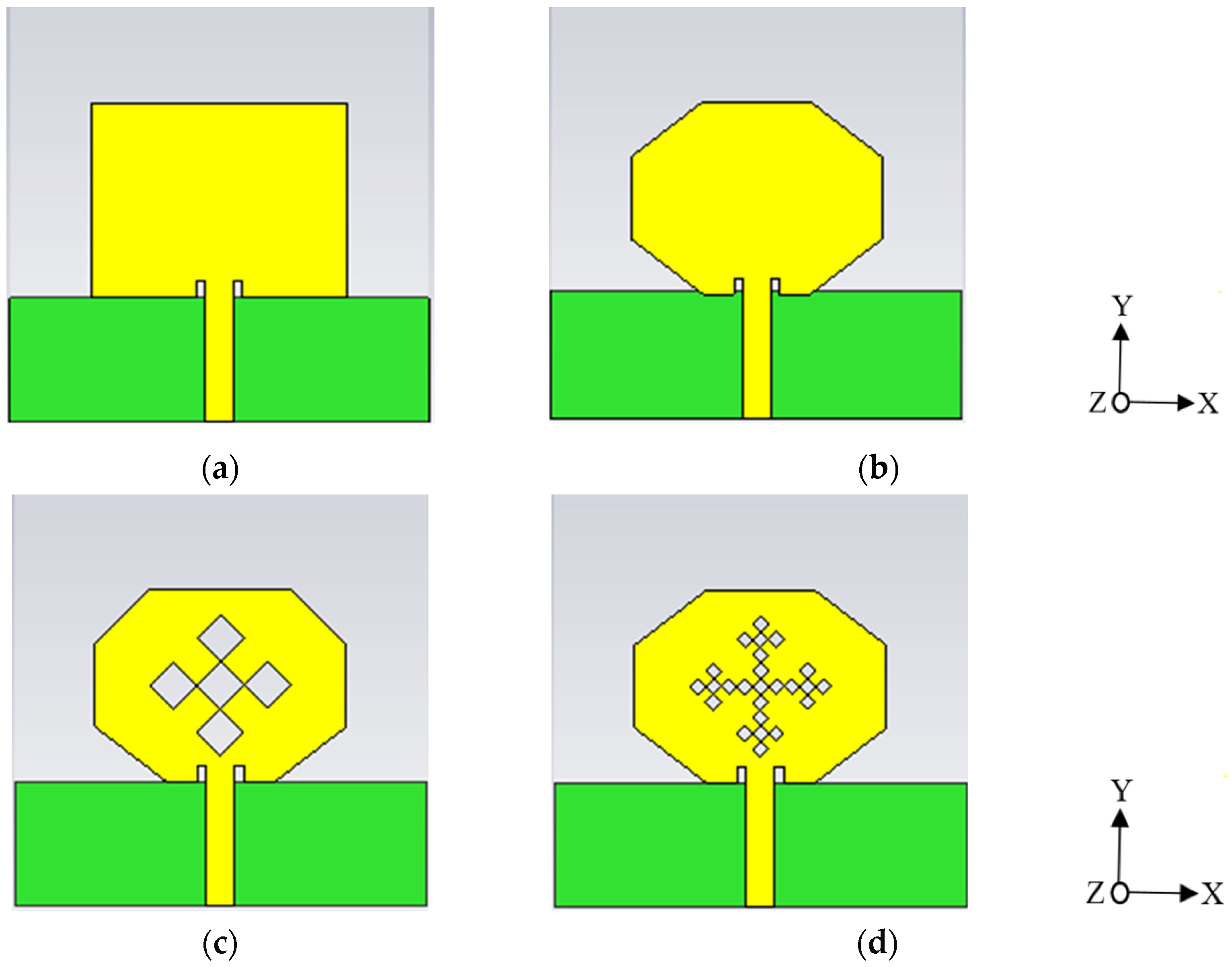
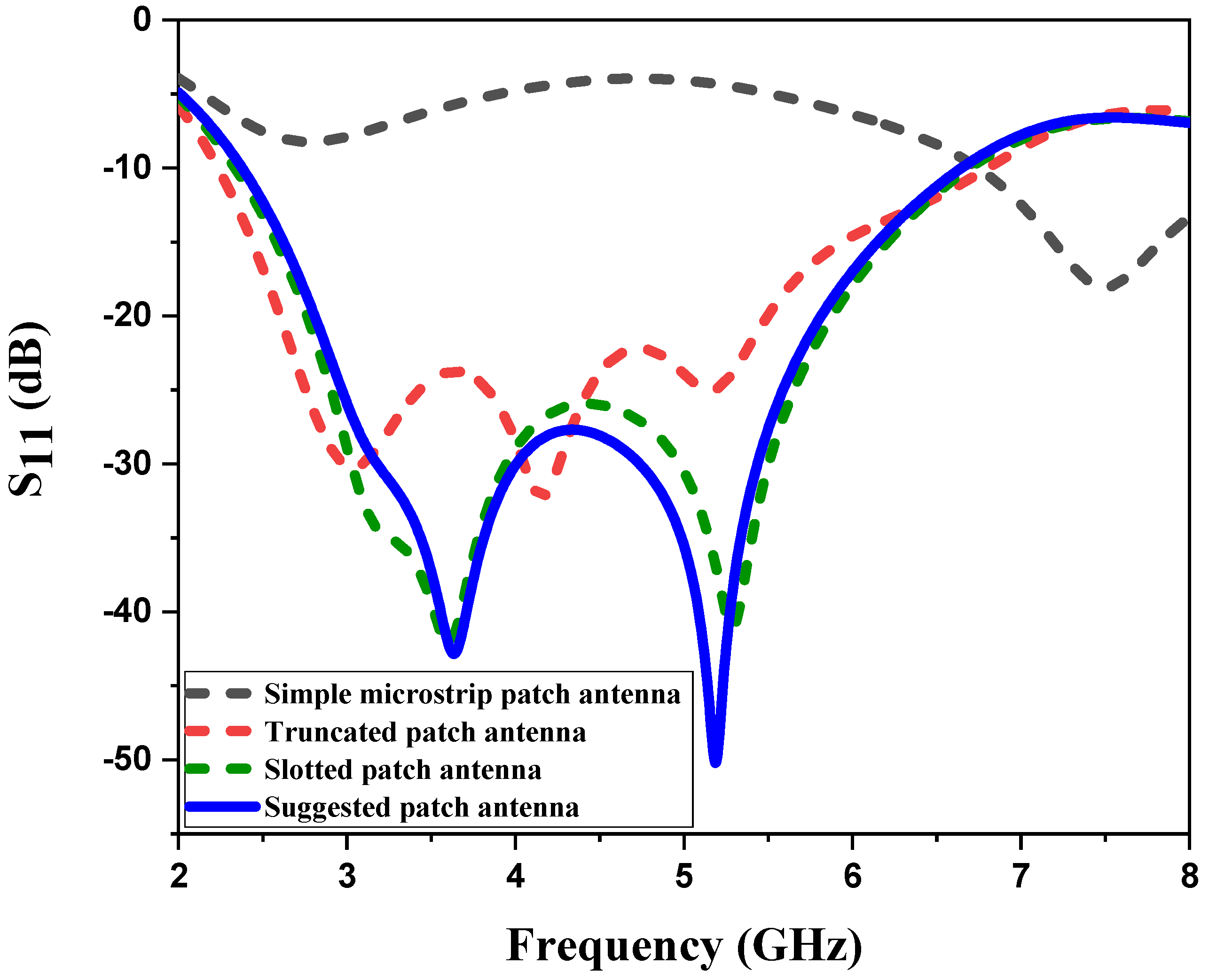
2.2. Design Evolution Procedure
2.3. Parametric Analysis of the Suggested Antenna
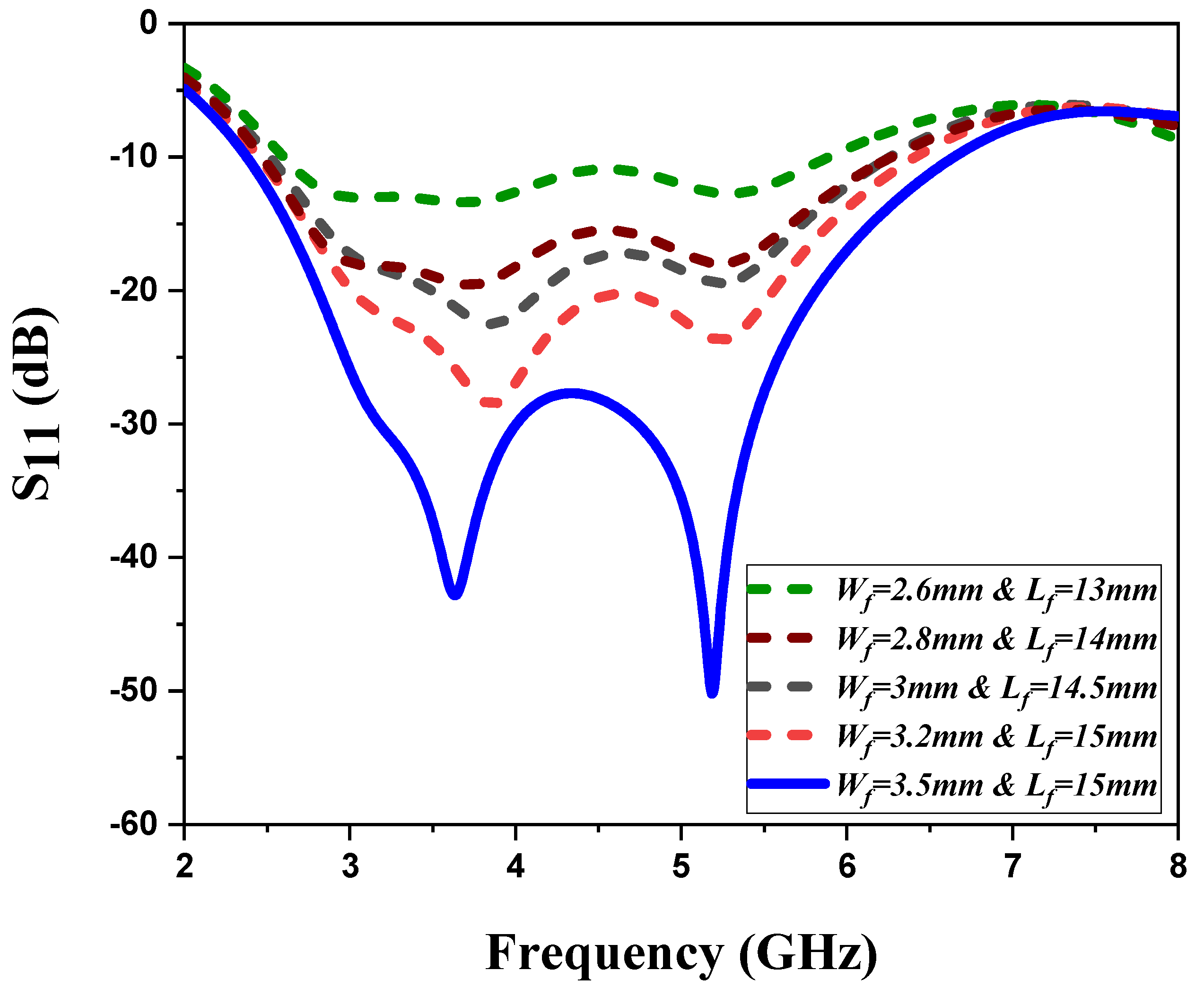
2.3.1. The Feed Line Length Lf and Width Wf Variation Effects
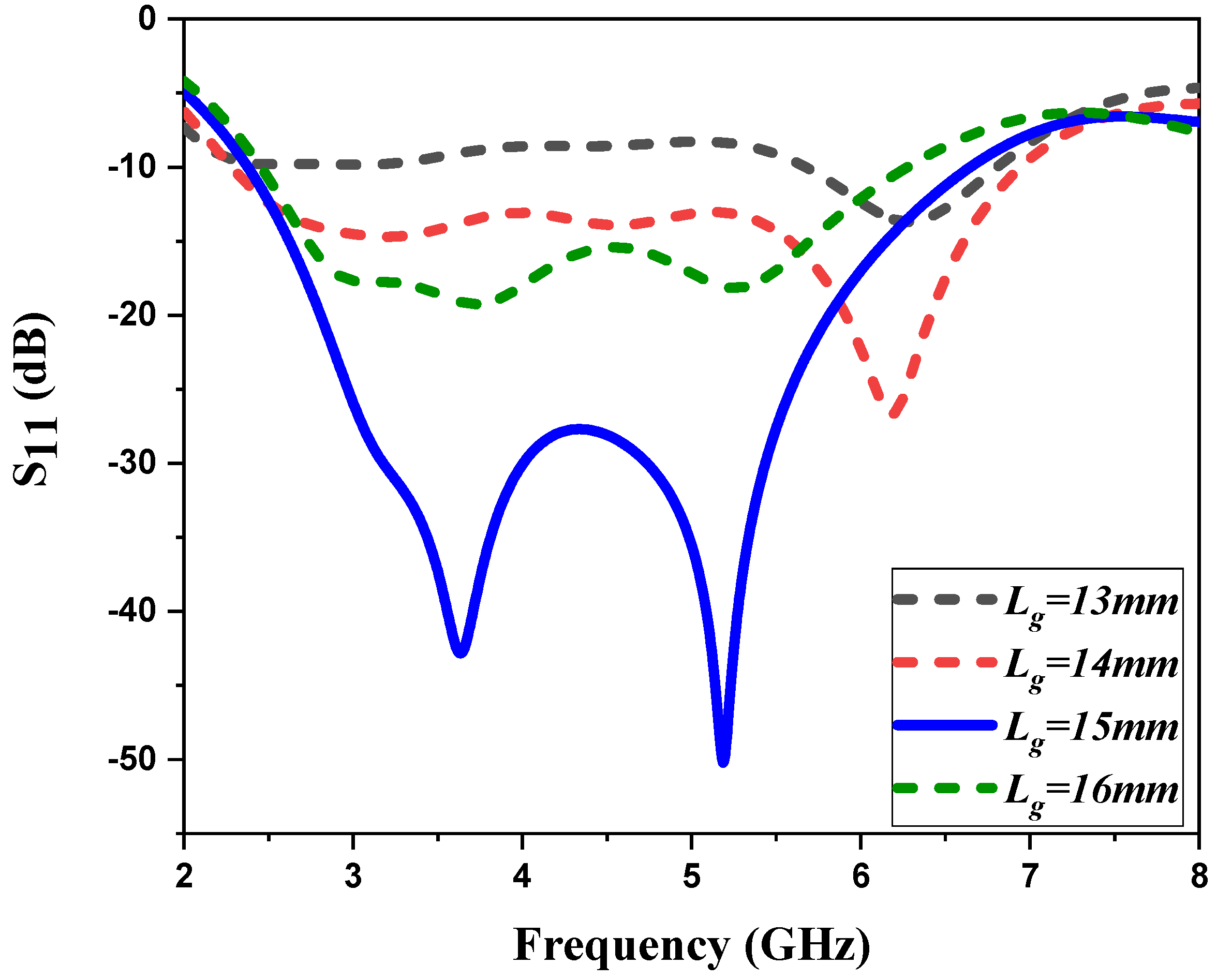
2.3.2. The Ground Plane Length Lg Variation Effects
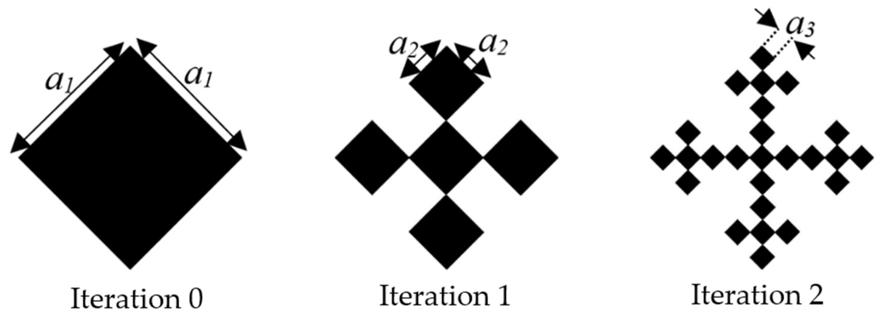
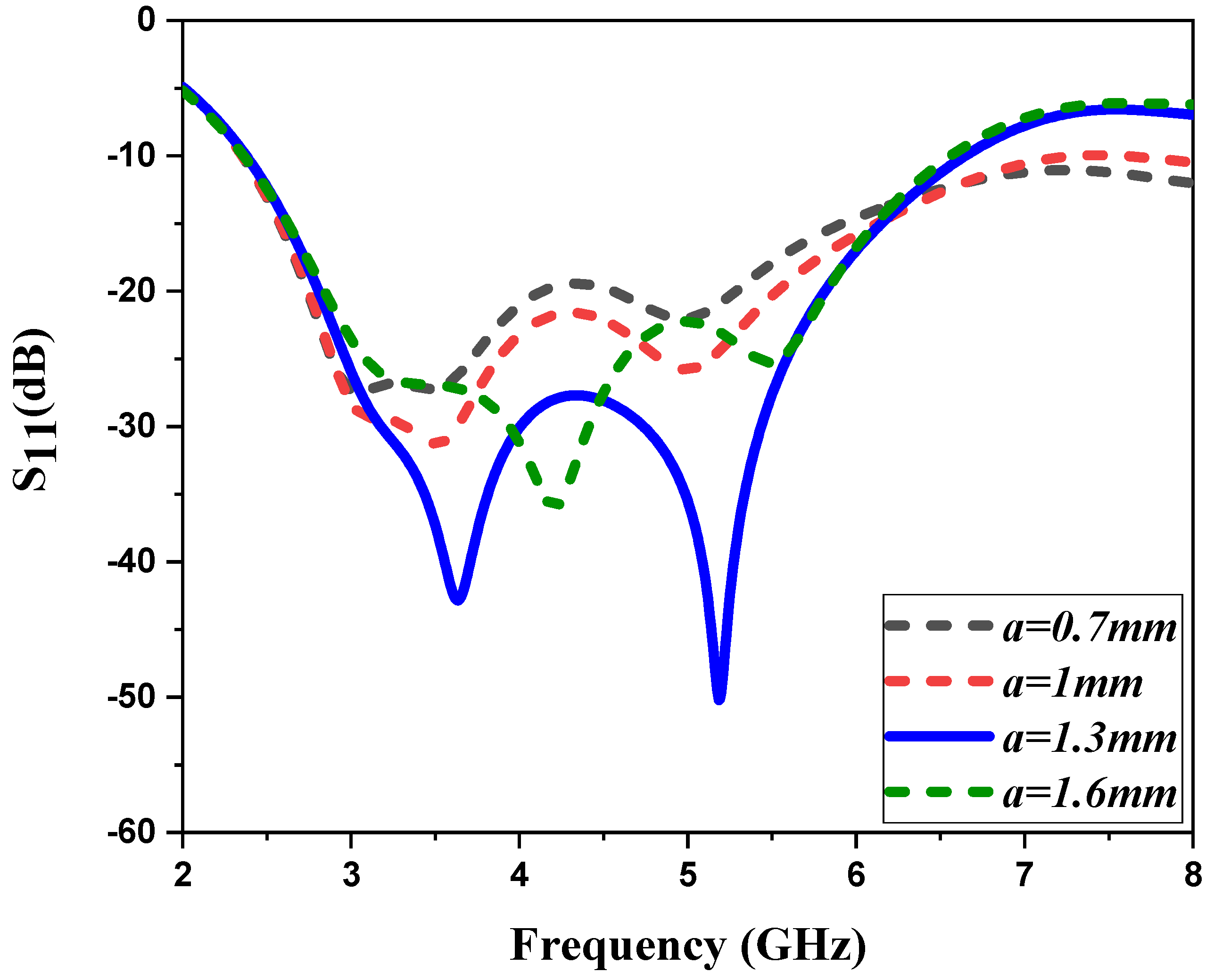
2.3.3. The Vicsek Slot Length Variation Effects
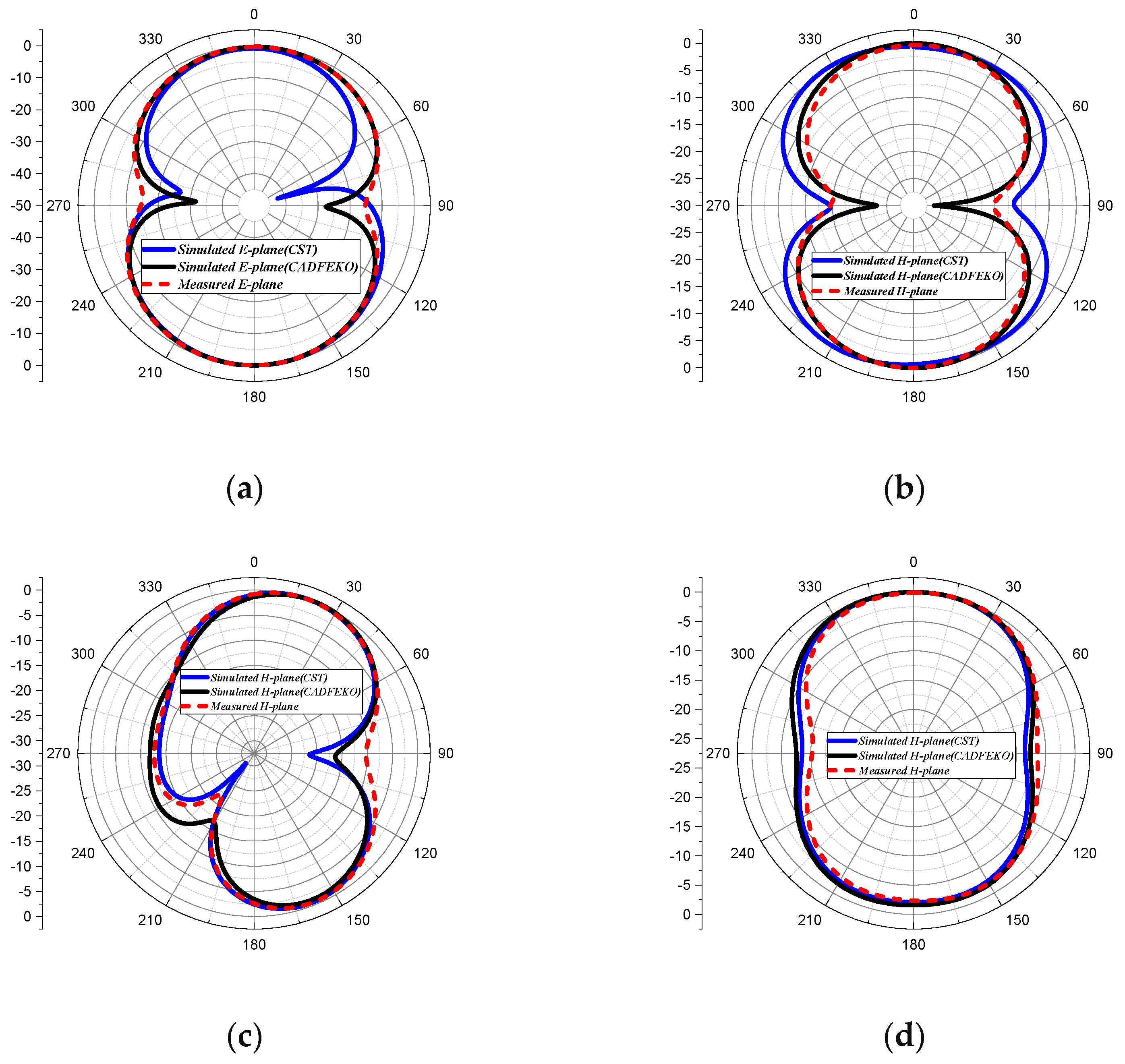
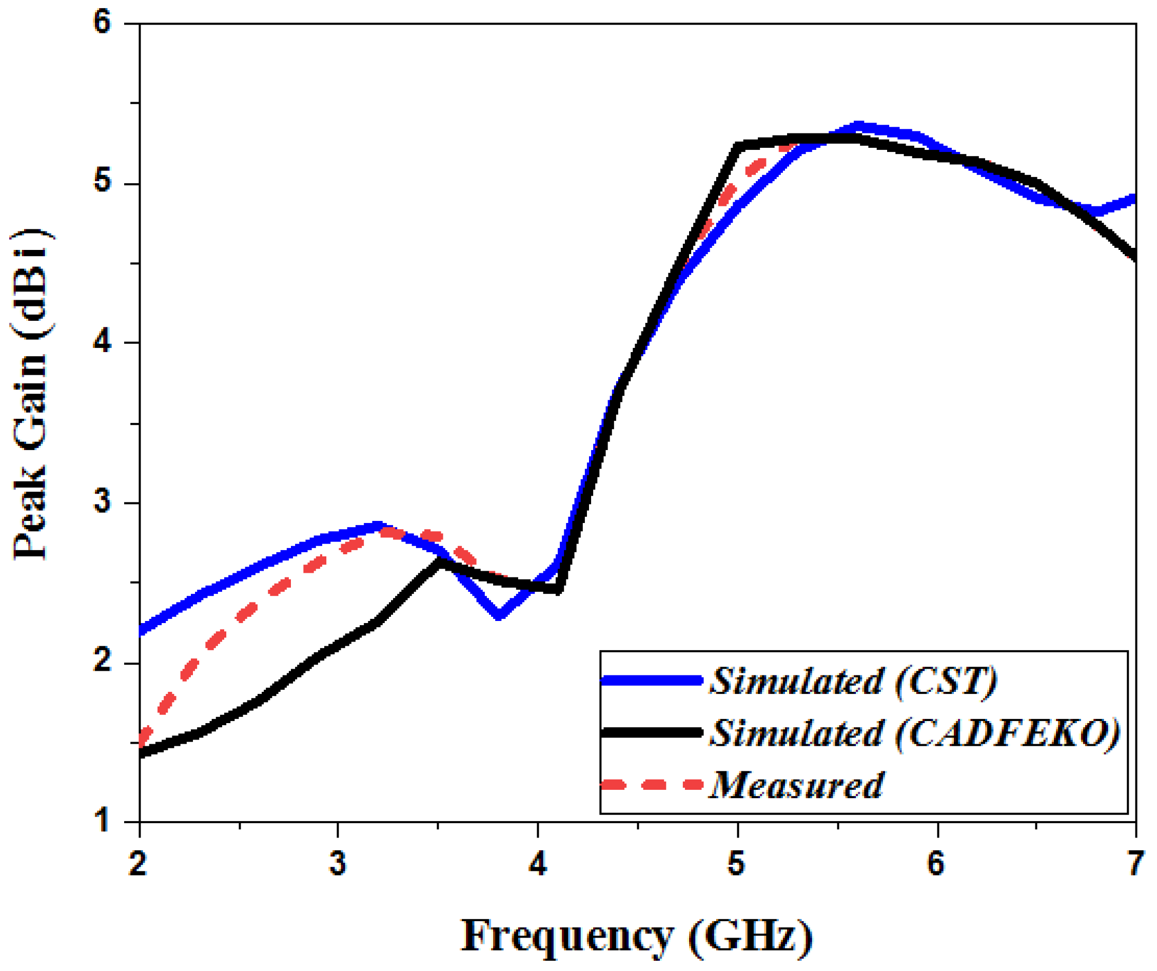
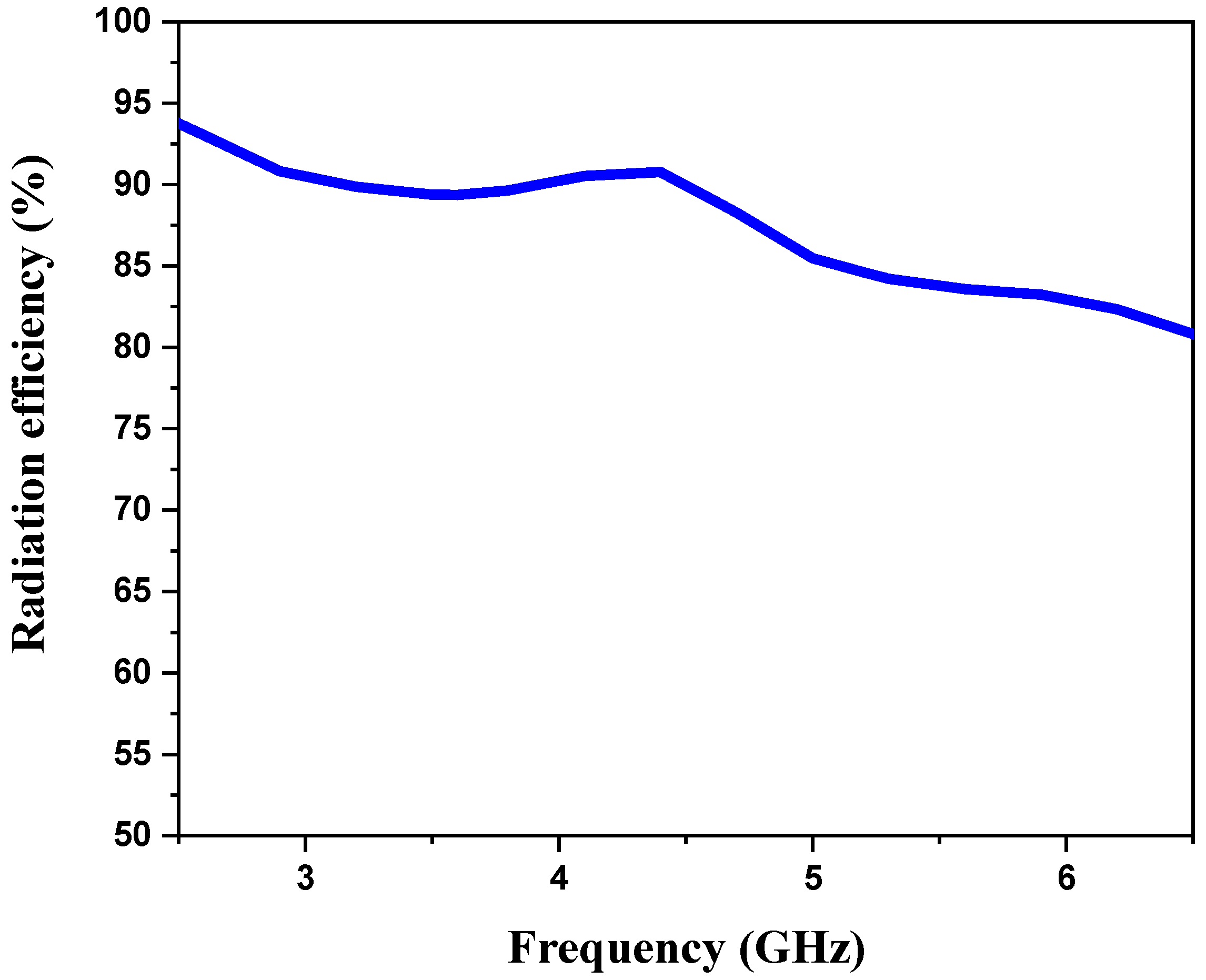
3. Results and Discussion
4. Conclusions
Author Contributions
Funding
Institutional Review Board Statement
Informed Consent Statement
Data Availability Statement
Acknowledgments
Conflicts of Interest
References
- Prashanth, K.V.; Umamaheswari, B.; Akhil, G.; Krishna, G.V.; Chandu, M.V.S. A Compact Antenna with WiMAX and WLAN bands notched for UWB applications. IJET 2018, 7, 489. [Google Scholar] [CrossRef] [Green Version]
- Chandan. Truncated Ground Plane Multiband Monopole Antenna for WLAN and WiMAX Applications. IETE J. Res. 2020, 1–6. [Google Scholar] [CrossRef]
- Geetharamani, G.; Aathmanesan, T. A Metamaterial Inspired Tapered Patch Antenna for WLAN/WiMAX Applications. Wirel. Pers. Commun. 2020, 113, 1331–1343. [Google Scholar] [CrossRef]
- Al-Gburi, A.J.A.; Ibrahim, I.B.M.; Zeain, M.Y.; Zakaria, Z. Compact Size and High Gain of CPW-Fed UWB Strawberry Artistic Shaped Printed Monopole Antennas Using FSS Single Layer Reflector. IEEE Access 2020, 8, 92697–92707. [Google Scholar] [CrossRef]
- Benkhadda, O.; Saih, M.; Chaji, K.; Reha, A. Design and Analysis of Rectangular Microstrip Patch Antenna using Different Feeding Mechanisms for 2.45 GHz Applications. JARDCS 2020, 12, 1205–1217. [Google Scholar] [CrossRef]
- Liu, G.; Liu, Y.; Gong, S. Compact tri-band wide-slot monopole antenna with dual-ring resonator for WLAN/WiMAX applications. Microw. Opt. Technol. Lett. 2016, 58, 1097–1101. [Google Scholar] [CrossRef]
- Reha, A.; El Amri, A. Design, Realization and Measurements of CPW-Fed Miscrostrip Hexagonal Patch Antenna with H-Tree Fractal Slots for WLAN and WIMAX Applications. IJMOT 2016, 11, 251–258. [Google Scholar]
- Tarbouch, M.; El Amri, A.; Terchoune, H.; Barrou, O. Compact CPW-Fed Microstrip Octagonal Patch Antenna with Hilbert Fractal Slots for WLAN and WIMAX Applications. In Innovations in Smart Cities and Applications; Ahmed, M.B., Boudhir, A.A., Eds.; Springer International Publishing: Cham, Germany, 2018; Volume 37, pp. 432–444. [Google Scholar] [CrossRef]
- Reha, A.; El Amri, A.; Benhmammouch, O.; Said, A.O.; El Ouadih, A.; Bouchouirbat, M. CPW-fed slotted CANTOR Set fractal antenna for WiMAX and WLAN applications. Int. J. Microw. Wirel. Technol. 2017, 9, 851–857. [Google Scholar] [CrossRef]
- Rahman, M.; NagshvarianJahromi, M.; Mirjavadi, S.; Hamouda, A. Compact UWB Band-Notched Antenna with Integrated Bluetooth for Personal Wireless Communication and UWB Applications. Electronics 2019, 8, 158. [Google Scholar] [CrossRef] [Green Version]
- Li, L.; Zhang, X.; Yin, X.; Zhou, L. A Compact Triple-Band Printed Monopole Antenna for WLAN/WiMAX Applications. Antennas Wirel. Propag. Lett. 2016, 15, 1853–1855. [Google Scholar] [CrossRef]
- Ibrahim, A.; Fazil, N.A.; Dewan, R. Triple-band antenna with defected ground structure (DGS) for WLAN/WiMAX applications. J. Phys. Conf. Ser. 2020, 1432, 012071. [Google Scholar] [CrossRef]
- Brar, R.S.; Saurav, K.; Sarkar, D.; Srivastava, K.V. A quad-band dual-polarized monopole antenna for GNSS/UMTS/WLAN/WiMAX applications. Microw. Opt. Technol. Lett. 2018, 60, 538–545. [Google Scholar] [CrossRef]
- Naik, K.K. Asymmetric CPW-fed SRR patch antenna for WLAN/WiMAX applications. AEU Int. J. Electron. Commun. 2018, 93, 103–108. [Google Scholar] [CrossRef]
- Kumar, D.N. Asymmetric CPW Fed Miniaturized dual polarized monopole Antenna for WLAN/WiMAX Applications. J. Phys. Conf. Ser. 2020, 1451, 012017. [Google Scholar] [CrossRef]
- Yeboah-Akowuah, B.; Tchao, E.T.; Ur-Rehman, M.; Khan, M.M.; Ahmad, S. Study of a printed split-ring monopole for dual-spectrum communications. Heliyon 2021, 7, e07928. [Google Scholar] [CrossRef]
- Palandoken, M. Dual broadband antenna with compact double ring radiators for IEEE 802.11 ac/b/g/n WLAN communication applications. Turk. J. Electr. Eng. Comput. Sci. 2017, 25, 1325–1333. [Google Scholar] [CrossRef]
- Chu, H.B.; Shirai, H. A compact metamaterial quad-band antenna based on asymmetric E-CRLH unit cells. PIER C 2018, 81, 171–179. [Google Scholar] [CrossRef] [Green Version]
- Chouhan, S.; Panda, D.K.; Kushwah, V.S.; Singhal, S. Spider-shaped fractal MIMO antenna for WLAN/WiMAX/Wi-Fi/Bluetooth/C-band applications. AEU Int. J. Electron. Commun. 2019, 110, 152871. [Google Scholar] [CrossRef]
- Ali, W.A.E.; Ashraf, M.I.; Salamin, M.A. A dual-mode double-sided 4 × 4 MIMO slot antenna with distinct isolation for WLAN/WiMAX applications. Microsyst. Technol. 2021, 27, 967–983. [Google Scholar] [CrossRef]
- Altaf, A.; Seo, M. Dual-Band Circularly Polarized Dielectric Resonator Antenna for WLAN and WiMAX Applications. Sensors 2020, 20, 1137. [Google Scholar] [CrossRef] [Green Version]
- Liu, S.; Wu, W.; Fang, D.-G. Single-Feed Dual-Layer Dual-Band E-Shaped and U-Slot Patch Antenna for Wireless Communication Application. Antennas Wirel. Propag. Lett. 2016, 15, 468–471. [Google Scholar] [CrossRef]
- Balanis, C.A. Antenna Theory: Analysis and Design, 3rd ed.; John Wiley: Hoboken, NJ, USA, 2005. [Google Scholar]
- Abdulbari, A.A.; Jawad, M.M.; Hanoosh, H.O.; Saare, M.A.; Lashari, S.A.; Sari, S.A.; Ahmad, A.; Khalill, Y.; Hussain, Y.M. Design compact microstrip patch antenna with T-shaped 5G application. Bull. Electr. Eng. Inform. 2021, 10, 2072–2078. [Google Scholar] [CrossRef]
- Bilgin, G.; Yilmaz, V.S.; Kara, A.; Aydin, E. Comparative assessment of electromagnetic simulation tools for use in microstrip antenna design: Experimental demonstrations. Microw. Opt. Technol. Lett. 2019, 61, 349–356. [Google Scholar] [CrossRef]


| Parameters | Dimensions (mm) | Parameters | Dimensions (mm) |
|---|---|---|---|
| Ws | 50 | W | 13 |
| Ls | 50 | L | 10 |
| Wf | 3.5 | a | 1.3 |
| Lf | 15 | g | 2 |
| Lg | 15 | d | 1 |
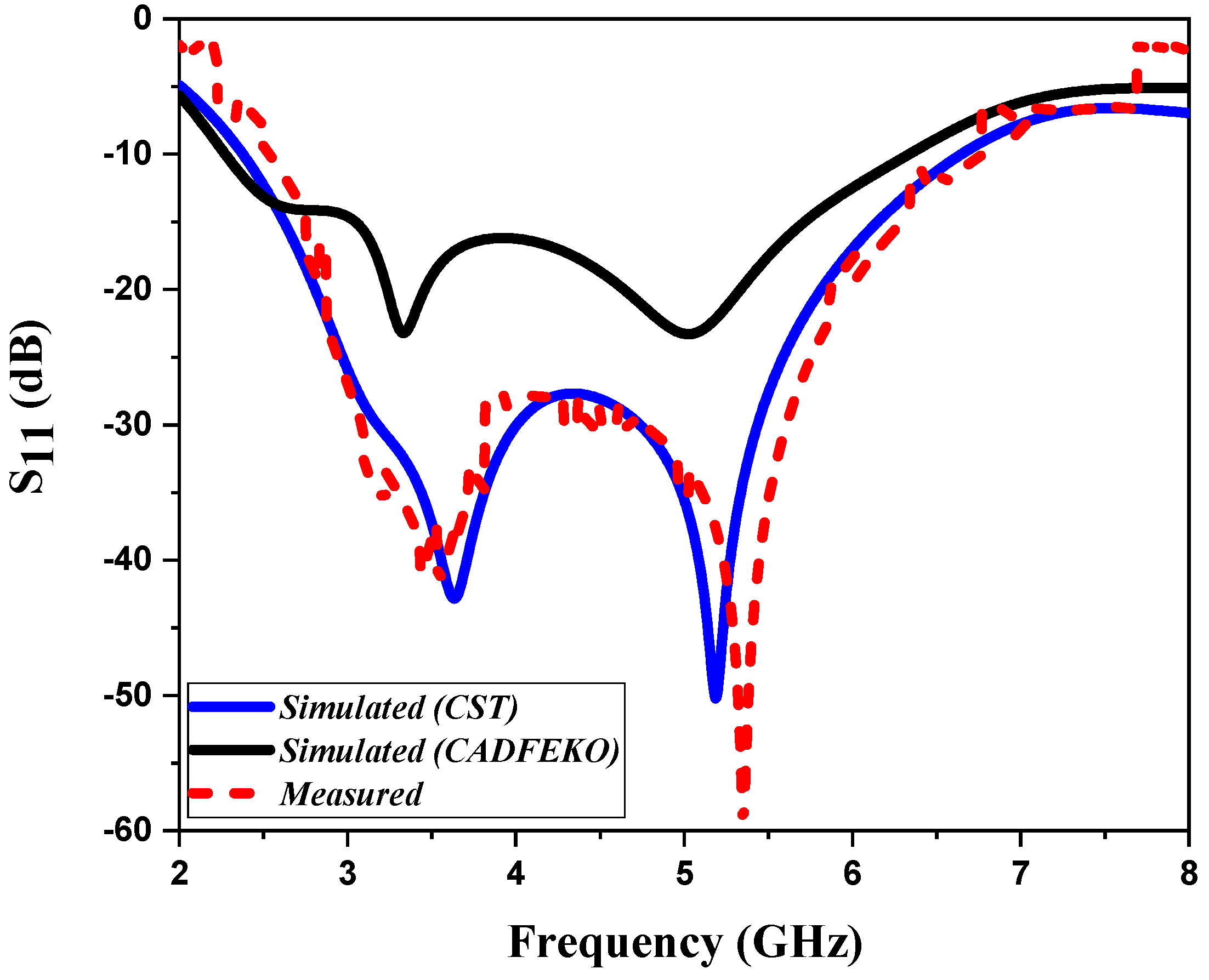
| Antenna Performance | Simulated (CADFEKO) | Simulated (CST) | Measured | |||
|---|---|---|---|---|---|---|
| fr (GHz) | 3.5 | 5.1 | 3.6 | 5.2 | 3.6 | 5.3 |
| S11 (dB) | −23.3 | −23.9 | −42.7 | −50.06 | −41.3 | −57.2 |
| Gain (dBi) | 2.63 | 5.26 | 2.7 | 5.36 | 2.78 | 5.32 |
| Bandwidth (GHz) | 4.15 | 4.35 | 4.22 | |||
| Ref No. | Size (mm2) | Type of Substrate | Frequency Range (GHz) | Bandwidth (GHz) | Resonant Frequency (GHz) | Peak Gain (dBi) |
|---|---|---|---|---|---|---|
| [17] | 60 × 90 | FR-4 |
2.3–3 4.7–6 | 0.7, 1.3 | 2.4, 5.2, 5.6 | 4.76, 2.9, 2.44 |
| [18] | 57 × 31.2 | FR-4 |
2.3–2.6 2.9–3.8 4.8–5.65 | 0.3, 0.9, 0.85 | 2.45, 3.5, 5.5 | 1.19, 1.59, 2.39 |
| [19] | 56 × 37 | FR-4 |
2.24–2.5 3.6–3.99 4.4–4.6 5.71–5.9 | 0.26, 0.39, 0.2, 0.19 | 2.43, 3.83, 4.48, 5.8 | 2.2, 2.8, 3.3, 4.2 |
| [20] | 60 × 60 | FR-4 |
2.3–2.6 3.3–3.7 | 0.3, 0.4 | 2.46, 3.5 | 2.61, 2.7 |
| [21] | 120 × 70 | Taconic RF-35 | 2.2–4.18 | 1.98 | 2.46, 3.5 | 4.11, 6.48 |
| [22] | 60 × 45 | FR-4 |
2.25–2.95 3.35–3.61 | 0.7, 0.26 | 2.6, 3.5 | 7.1, 7.3 |
| This work | 50 × 50 | FR-4 | 2.48–6.7 | 4.22 | 3.6, 5.3 | 2.78, 5.32 |
Publisher’s Note: MDPI stays neutral with regard to jurisdictional claims in published maps and institutional affiliations. |
© 2022 by the authors. Licensee MDPI, Basel, Switzerland. This article is an open access article distributed under the terms and conditions of the Creative Commons Attribution (CC BY) license (https://creativecommons.org/licenses/by/4.0/).
Share and Cite
Benkhadda, O.; Ahmad, S.; Saih, M.; Chaji, K.; Reha, A.; Ghaffar, A.; Khan, S.; Alibakhshikenari, M.; Limiti, E. Compact Broadband Antenna with Vicsek Fractal Slots for WLAN and WiMAX Applications. Appl. Sci. 2022, 12, 1142. https://0-doi-org.brum.beds.ac.uk/10.3390/app12031142
Benkhadda O, Ahmad S, Saih M, Chaji K, Reha A, Ghaffar A, Khan S, Alibakhshikenari M, Limiti E. Compact Broadband Antenna with Vicsek Fractal Slots for WLAN and WiMAX Applications. Applied Sciences. 2022; 12(3):1142. https://0-doi-org.brum.beds.ac.uk/10.3390/app12031142
Chicago/Turabian StyleBenkhadda, Omaima, Sarosh Ahmad, Mohamed Saih, Kebir Chaji, Abdelati Reha, Adnan Ghaffar, Salahuddin Khan, Mohammad Alibakhshikenari, and Ernesto Limiti. 2022. "Compact Broadband Antenna with Vicsek Fractal Slots for WLAN and WiMAX Applications" Applied Sciences 12, no. 3: 1142. https://0-doi-org.brum.beds.ac.uk/10.3390/app12031142