
Brake-Disc Holes and Slit Shape Design to Improve Heat Dissipation Performance and Structural Stability


1
Department of Mechanical Engineering, Yeungnam University, Gyeongsan-si 38541, Gyeongsangbuk-do, Korea
2
Structure CAE Team, SL Corporation, 77 Gongdan 6-ro, Jillyang-eup, Gyeongsan-si 38470, Gyeongsangbuk-do, Korea
3
Department of Mechanical Engineering, University of Alaska Fairbanks, Fairbanks, AK 99775-5905, USA
*
Author to whom correspondence should be addressed.
Appl. Sci. 2022, 12(3), 1171; https://0-doi-org.brum.beds.ac.uk/10.3390/app12031171
Submission received: 21 December 2021
/
Revised: 19 January 2022
/
Accepted: 20 January 2022
/
Published: 23 January 2022
(This article belongs to the Special Issue New Achievements in Structural Dynamics Analysis)
Abstract
:A brake disc decelerates the vehicle through friction with the brake pads. When the brake system is overheated, brake fade can occur, in which the friction coefficient drops significantly. Additionally, an over-heated brake system may cause vapor lock, in which the brake hydraulic fluid is vaporized. These phenomena can lead to the loss of braking power and cause a fatal accident. Therefore, brake systems must have stable braking and heat dissipation performance. Having through-holes and slits on the friction surface of the rotor has been adopted to improve the heat dissipation performance, but the holes become stress points and potentially cause cracks. Therefore, brake systems should be designed to have structural stability as well as good heat dissipation. In this study, finite element (FE) modeling was developed to analyze the structural stability and heat dissipation performance of a brake system, and structural and thermal simulations were performed in ANSYS, a CAE software package. In addition, to minimize concentrated stress and temperature, optimal design of the shape and pattern of holes and slits was carried out using PIAnO, an integrated optimal design software package. The first step of design optimization was performed while considering the shape and pattern of the disc holes and slits as design factors. Among the design factors, those with the largest effects on the objective functions were found and set as new design factors to perform the second step. The designs were compared to existing discs. Through the optimization presented in this paper, it is expected that the performance of the braking system will improve and the life of the brake parts will be increased.
1. Introduction
A disc brake is a braking system composed of a brake rotor, brake pads, and calipers. The brake rotor rotates with the wheel, and the brake pads are mounted on the brake calipers, which clamp the rotor to stop or slow the wheel. The brake pads generate frictional heat by converting kinetic energy into thermal energy to reduce the kinetic energy of the vehicle. Consequently, due to the thermal energy generated during the braking process, the disc temperature rises on the friction part and fatigue accumulates, causing cracks that decrease the life of the disc.
There is a trade-off relationship between the cooling performance and structural stability of a brake disc [1,2]. Ventilated discs are generally used to improve the heat dissipation performance. A ventilated disc has the form of a general disc with added ventilation blades that help dissipate heat. As it is cooled with air circulation by the ventilation blades, when it rotates at a higher speed, high centrifugal force facilitates heat dissipation. In addition, the temperature rise can be suppressed even at medium and low speeds with small centrifugal force through holes on the outer surface, and the cooling performance can be maximized by interlocking with the ventilation blades.
The holes and slits have advantages of improving the braking performance by improving the frictional force, heat dissipation, dust and gas emission, disc deformation and fading, and weight reduction. However, thermal stress is concentrated around the holes [3]. Previous studies have shown that concentrated stress is related to the starting points of crack growth [4]. Therefore, it can be estimated that the possibility of crack growth due to concentrated stress increases around the holes and slits.
Studies in structural and thermal characteristics and their correlations with stability and lifespan using finite element analysis have been conducted [5,6,7,8]. There have also been studies on the shape of the disc, but the number of disc samples that were tested or analyzed was limited [9,10,11,12]. In this study, in order to understand structural stability and thermal characteristics when designing a brake disc, ANSYS and PIAnO software were utilized to optimally design a brake disc. Stress and temperature were set as objective functions, and hole shapes of the disc, arrangement patterns, and ventilation blades were set as design variables.
Through optimal design formulation, results were derived using the design of experiments (DOE). In addition, factors that have the largest effect on the objective functions were used to carry out the second optimal design. Through this study, a brake disc shape model with improved structural stability and cooling performance compared to conventional discs is presented.
2. Brake Disc Analysis and Optimal Design Procedure
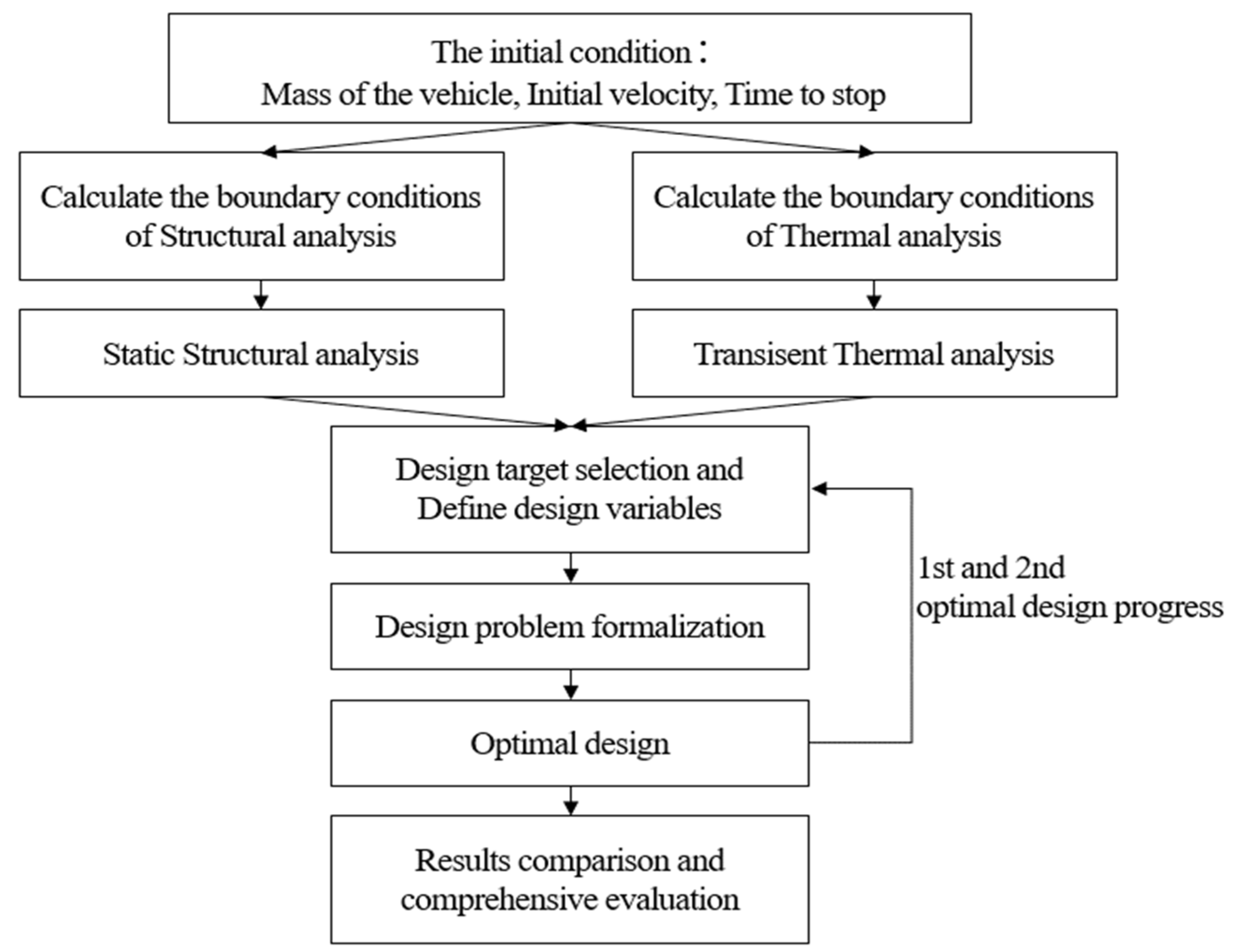
The procedure for the optimal design is shown in Figure 1. Before the analysis, the initial state of the target vehicle was determined to establish the boundary conditions. Table 1 shows the initial state. It was assumed that the input pressure of the pad forms a pressure distribution in the portions of the disc and the pad in contact with each other, and that all the kinetic energy of the running vehicle is converted into thermal energy by friction between the brake disc and the pad during braking. Structural and thermal analyses were performed in the initial state.
The boundary conditions in the structural analysis were set by calculating the rotation speed and pressure based on Table 1. The value of the heat flux is an input condition for the thermal analysis and was set through calculation. The data provided by the ANSYS program were used for the convective heat transfer coefficient of air [13]. Objective functions and design factors were selected for the optimal design. To analyze the problem of crack formation due to stress, stress and temperature minimizations were set as objective functions. The hole shapes and the arrangement patterns are the elements which have the largest effects on the objective functions and were therefore determined as design factors to formulate the optimal design.
The optimal design was carried out with an orthogonal arrangement that enables efficient design and analysis with only a small number of experiments by using the design of experiment methods. In the case of the orthogonal arrangement, it was judged that there is a possibility that there could be more improved design points in the design area because only minimal experiments were conducted for design efficiency. Therefore, an additional experiment was planned with the design factors that had the largest effects on the minimization of the objective functions. Finally, an improved brake disc model compared to the existing disc was derived.
3. Finite Element Simulation
3.1. Analysis Model
The brake disc in this study is a ventilated disc, and the structure is shown in Figure 2. A ventilated disc is a structure composed of two solid discs and ventilation blades between the solid discs [14]. Most vehicle brakes are made of cast iron. The material property values are described in Table 2. As the rotor and blade shapes were designed, the diameters and thicknesses of the models were drawn using the CATIA tool. As shown in Figure 3, the total height is 57 mm, the disc thickness is 15 mm, the outer diameter is 250 mm, and the inner diameter is 90 mm.
3.2. Analysis Conditions
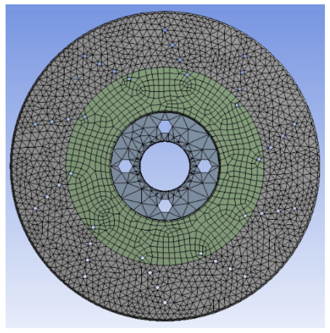
Figure 4 shows the mesh model of the brake disc for finite element analysis. The following mesh generation form was applied because it is effective for accuracy and time efficiency [15]. The mesh size of the disc surface and the inner surface of the ventilation blade set to 5 mm, the mesh method was set to hex dominant, and face sizing was set to quad/tri. Two different analyses were conducted: structural analysis and thermal analysis. The structural analysis was carried out to identify the stress distribution on the surface of the brake disc due to the pressure of the pad, and the thermal analysis was carried out to identify the temperature of the surface of the brake disc in the process through which the heat generated after braking is dissipated.
3.3. Structural Analysis
Immediately after braking, the disc brake is the most vulnerable. Therefore, the moment immediately after the braking was selected as the time zone for static analysis. The part of the brake that comes into contact with the brake pad was set as the area where the pressure acts, and it was assumed that the pressure of the pad acts on the corresponding area of the disc rotor. The area where the wheel and hub meet with each other was fixed through a fixed support.
Referring to Table 1, the rotational speed of the disc and the pressure of the brake pad were calculated through Equations (1)–(3), and the results were set as boundary conditions [16]. The rotation speed is shown in Equation (1).
where v is the initial speed (m/s) and Rtire is the radius of the vehicle wheel (m). The force that acts on the brake disc is shown in Equation (2).
where M, t, and Rrotor are the weight of the vehicle (kg), the stopping time (s), and the effective rotor radius (m), respectively.
The external pressure P between the disc and the pad was calculated with the force applied to the disc and is shown in Equation (3).
where Fdisc is the force (N) acting on the disc, Ac is the surface of the pad in contact with the disc (), and μ is the coefficient of friction. The boundary conditions are found in Figure 5 and Table 3.
The stress of the disc was derived through the finite element-based structural analysis. Figure 6. shows the distribution of the von Mises stress in the disc. It was confirmed that the stress distribution mainly appeared around the holes and the ventilation blades. The degree of stress concentration differed depending on the location of the hole, concentrated stress appeared around the holes in the rotor, and the highest stress occurred in parts of the ventilation blades. High stress causes cracks and decreases the life of the disc, and if it is repeated continuously, the disc can rupture [17].
3.4. Thermal Analysis
The same conditions as in the previous structural analysis were used in the next analysis. Identical pressure of the pad was applied as in the structural analysis, and it was assumed that the pressure would be applied continuously over time. The boundary conditions are found in Figure 7.
In order to check the process through which the heat of the disc is dissipated over time, the heat flux was set as a function of time through calculation [18]. In addition, with regard to the heat flux, it was assumed that all the kinetic energy of the running vehicle would be converted into thermal energy due to the friction between the brake disc and the pad during braking. The area of the heat flux was set to the area where the disc rotor is compressed by the pad so that frictional heat is generated. The kinetic energy generated during running and the heat flux due to friction were calculated with Equations (4) and (5) and Table 1. The derived values are as follows [19]:
where is the weight of the vehicle (kg), and is the initial speed (m/s). Q is the thermal energy, t is the stopping time (s), and is the surface of the pad that comes into contact with the disc ().
The distribution of the braking torque between the front and rear axles was assumed to be 7:3, and the heat flux of each front axle is shown in Equation (6) below [20].
The initial temperature of the disc was 20 °C, and the convective heat transfer coefficient of air was applied to all contact areas between the disc and air using the stagnant air-simplified case data provided by the ANSYS program.
The derived temperature distribution of the brake disc is shown in Figure 8. Due to the cooling effect of the ventilation blades, the temperature around the ventilation blades was lower than that of the surroundings, and distributions of higher temperatures can be identified in areas closer to the outside of the disc. As the temperature rises, the durability of the disc decreases rapidly. Therefore, the ventilation performance should be improved because high temperatures can cause fatal thermal problems such as permanent disc deformation and changes in the friction coefficient.
4. Design Optimization
4.1. Formulation of Design Problems
The larger the numbers of holes and ventilation blades, the better the heat dissipation performance is. However, as the heat dissipation area increases due to the holes and ventilation blades, various problems occur such as concentrated stresses and, consequently, crack formation. Optimization was aided to design a shape and pattern of the holes and ventilation blades leading to the minimum concentrated stress and disc temperature.
Four design elements in the shape of the brake disc that affect the objective function were the shape of the holes, the number of holes, the diameter of the holes, and the diameter of the ventilation blades. The optimal design problem can be formulated as shown in Equation (7) below. In addition, there are three shapes of apertures: holes, slits, and a mixture of holes and slits, as shown in Table 4. The values of three variables (except for the hole types) were defined in the form of continuous variables with lower and upper limit values. After the formulation was carried out, the brake disc model was transformed by dimension within the ranges of design variables to carry out brake-disc modeling and analysis.
Find Hole-Shape, Number, Diameter,
Ventilation Blade–Diameter
To minimize Stress, Temperature
Shape = {Holes, Slits, and Holes and Slits}
10 ≤ Number of Hole ≤ 30
4 mm ≤ Diameter of Hole ≤ 8 mm
4 mm ≤ Diameter of Ventilation Blade ≤ 8 mm
Ventilation Blade–Diameter
To minimize Stress, Temperature
Shape = {Holes, Slits, and Holes and Slits}
10 ≤ Number of Hole ≤ 30
4 mm ≤ Diameter of Hole ≤ 8 mm
4 mm ≤ Diameter of Ventilation Blade ≤ 8 mm
4.2. Results of Optimal Design and Verification
For efficient design, the design of experiments (DOE) was used. A meta-model was created first to explore the design area, which requires a large number of analyses, and to proceed with an optimal design. In order to create a meta-model with PIAnO, which is integrated optimal design software, an orthogonal array enables efficient design and analysis with only a small number of experiments among various experimental design methods. As shown in Table 5, the design variables were defined as three factors related to the holes in the rotor and one ventilation blade that helps improve the internal heat dissipation performance (shape of holes, number of holes, diameter of holes, and diameter of ventilation blades), and each design variable was defined to have three levels.
ndv is the number of design factors.
The test points to be used in the meta-model were derived through the standards provided in PIAnO [21]. The standard for use of the test points is shown in Equation (8), and the selection of the number of test points is shown in Equation (9). The number of data (81) and the number of design variables (4) were substituted into Equation (8) to calculate the number of design factors, and the smallest value was selected among the resulting values. As the selected value was identified to be smaller than the number of data, the test points can be used. Thus, eight test points were created. The initial finite element model was modified to fit the design variables, and structural and thermal analyses were carried out in ANSYS. It was also repeated to derive the stress and temperature.
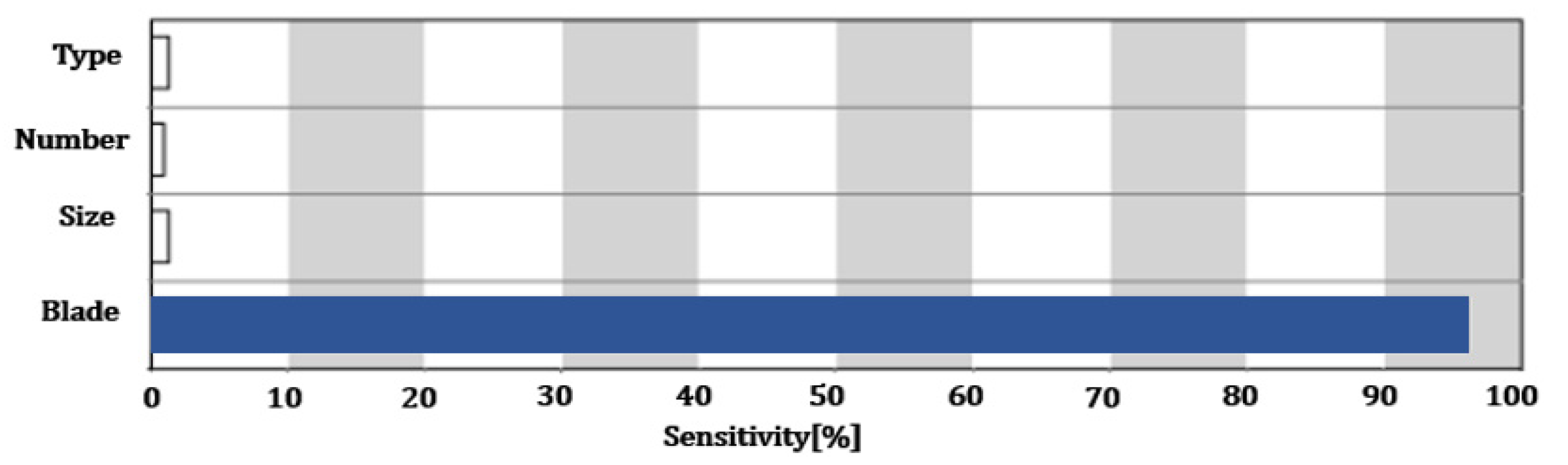
For orthogonal arrangement, a minimal experiment was conducted for design efficiency. As shown in Figure 9 and Figure 10, the effects of the design variables were identified on the sensitivity plot through the analysis of the sensitivity of major design variables that affect the objective functions in optimization. The factor which has the largest effect on the stress obtained through structural analysis is the diameter of the ventilation blades. Other factors have little effect. The factor that has the largest effect on the temperature obtained through thermal analysis is the hole type, followed by the hole size and ventilation blade.
The design variables and objective functions were defined to minimize stress and temperature through the Hybrid Metaheuristic Algorithm (HMA) to formulate the optimal design problem and derive the results. It was identified that the stress decreased by 18.19 MPa, from the initial value of 64.04 MPa to 45.85 MPa, and the temperature decreased by 6.57 °C, from 45.90 °C to 39.33 °C, compared to the plain solid disc. In addition, it was identified that the optimal values of the design variables were 30 holes, a diameter of holes of 4 mm, slit-shaped holes, and a diameter of the ventilation blades of 8 mm. The optimal values of the design variables are shown in Table 6.
In the design of orthogonal arrangement, there is a high possibility that there may be design points that can be further improved in the design area, because only the minimum experiment was conducted with only three levels in the design area for design efficiency. Therefore, additional optimizations were performed to consider only the ventilation blade, which is the variable that has the largest effect on stress. The ranges of design variables in the additional optimizations were set as shown in Equation (10). The shape of the blade is shown in Table 7. The values of three variables other than the blades were defined in the form of continuous variables with lower and upper limit values. The optimizations were conducted with an orthogonal arrangement identically to the earlier experiments, and each design variable was defined to have three levels.
Find Vane-Shape, Number, Diameter, Length
To minimize Stress, Temperature
Shape = {Radial, Curved, Pin-Fin}
5 ≤ Number of Ventilation Blade ≤ 30
2 mm ≤ Diameter of Ventilation Blade ≤ 6 mm
18 mm ≤ Length of Ventilation Blade ≤ 58 mm
To minimize Stress, Temperature
Shape = {Radial, Curved, Pin-Fin}
5 ≤ Number of Ventilation Blade ≤ 30
2 mm ≤ Diameter of Ventilation Blade ≤ 6 mm
18 mm ≤ Length of Ventilation Blade ≤ 58 mm
Eight test points were created, and the model was constructed with the design variables of the test points of the ventilation blade in consideration of the optimal value of the holes derived from the previous design variables. Individual structural and thermal analyses were then carried out. The design variables and objective functions were defined to minimize stress and temperature through the optimal plan to formulate the optimal design problem. When the values of the objective functions according to the weights were compared after the optimization work, it was judged to be important to consider both objective functions that had large changes compared to the initial values.
Therefore, the second optimal design was carried out, and it was identified that the stress decreased by 14.8 MPa, from 64.04 MPa to 49.20 MPa, and the temperature decreased by 10.77 °C, from 45.89 °C to 35.12 °C compared to the plain solid disc. The optimum values of the ventilation blades were found as follows: diameter of 4 mm, length of 58 mm, curved shape, and 30 blades. The optimum values are shown in Table 8.
5. Conclusions
In this study, finite element modeling was developed to analyze the structural stability and heat dissipation performance of a vehicle brake system. Model-based numerical simulations were performed to seek the optimal design of the brake disc, which minimizes concentrated stress and simultaneously improves cooling performance. The design optimization presented in this study took two steps. The first step was to find the optimal pattern of hole/slit, number of holes, hole diameter, and ventilation blade diameter. The second was to further optimize the brake disc by identifying the design factors that had the largest effects on the objective functions from Step 1 and setting them as new design factors. The findings from the design optimizations and simulations are summarized as follows:
- Through the primary optimization, the stress decreased by 28.4% compared to the initial model (solid disc), from 64.04 MPa to 45.85 MPa; the temperature decreased by 6.57 °C, from 45.90 °C to 39.33 °C.
- In order to further maximize the improvement, the second optimal design was performed in consideration of the ventilation blade design variable, which was identified as the design factor with the greatest influence on the objective function. Compared to the initial model, the stress was decreased by 23.2%, from 64.04 MPa to 49.20 MPa, and the temperature was decreased by 10.77 °C, from 45.89 °C to 35.12 °C, resulting in a further decreased temperature.
- The optimal shape of the final brake disc hole and the slit is identified as a “slit type” with 30 holes, with a diameter of 4 mm in shape at the rotor; the optimal ventilation blade shape at the protrusion is identified as a blade type with a length of 58 mm curved shape with a diameter of 4 mm.
Author Contributions
Conceptualization, S.P. and J.K.; methodology, S.P.; software, S.P. and K.L.; validation, S.P., K.L. and S.K.; formal analysis, S.P. and K.L.; investigation, S.P. and K.L; resources, S.P., K.L. and S.K.; data curation, S.P., S.K. and J.K.; writing—original draft preparation, S.P., K.L. and S.K.; writing—review and editing, S.K. and J.K.; visualization, S.P. and K.L.; supervision, S.K. and J.K.; project administration, J.K.; and funding acquisition, J.K. All authors have read and agreed to the published version of the manuscript.
Funding
This research was funding by National Research Foundation of Korea (NRF) funded by the Ministry of Education (2020R1I1A3A04036862) and a Yeungnam University Research Grant in 2021.
Institutional Review Board Statement
Not applicable.
Informed Consent Statement
Not applicable.
Acknowledgments
This research was supported by basic Science Research Program through the National Research Foundation of Korea (NRF) funded by the Ministry of Education (2020R1I1A3A04036862) and a Yeungnam University Research Grant in 2021.
Conflicts of Interest
The authors declare no conflict of interest.
References
- Belhocine, A.; Abdullah, O.I. Finite element analysis (FEA) of frictional contact phenomenon on vehicle braking system. Mech. Based Des. Struct. Mach. 2020, 1–36. [Google Scholar] [CrossRef]
- Jung, S.P.; Kim, Y.G.; Park, T.W. A study on thermal characteristic analysis and shape optimization of a ventilated disc. Int. J. Precis. Eng. Manuf. 2012, 13, 57–63. [Google Scholar] [CrossRef]
- Kang, H.; Jung, T.; Hong, Y.; Park, S. Effect of Cross-drilled Hole Shape on Crack of Disk Brake Rotor. J. Korean Soc. Automot. Eng. 2018, 26, 67–76. [Google Scholar] [CrossRef]
- Yildiz, Y.; Duzgun, M. Stress Analysis of Ventilated Brake Discs Using the Finite Element Method. Int. J. Automot. Technol. 2010, 11, 133–138. [Google Scholar] [CrossRef]
- Mahmod, M.I.; Munisamy, K.M. Experimental analysis of ventilated brake disc with different blade configuration. Dep. Mech. Eng. 2011, 1, 1–9. [Google Scholar]
- Belhocine, A.; Bouchetara, M. Thermal behavior of dry contacts in the brake discs. Int. J. Automot. Eng 2012, 3, 9–17. [Google Scholar]
- Babukanth, G.; Teja, M.V. Transient analysis of disk brake by using ANSYS software. Int. J. Mech. Ind. Eng. 2012, 2, 21–25. [Google Scholar] [CrossRef]
- Aleksendrić, D.; Barton, D.C. Neural network prediction of disc brake performance. Tribol. Int. 2009, 42, 1074–1080. [Google Scholar] [CrossRef]
- Sunil Kumar, B.V.; Sanjay, S.J.; Math, V.B. Modal Analysis of Annular Disc. Def 2014, 1, 172. [Google Scholar]
- Belhocine, A.; Ghazaly, N.M. Effects of material properties on generation of brake squeal noise using finite element method. Lat. Am. J. Solids Struct. 2015, 12, 1432–1447. [Google Scholar] [CrossRef]
- Velizade, E.S. Rational Design of Vehicle Braking Systems with Reduced Wear of Friction Lining. Прoблемы Машинoстрoения 2020, 23, 46–55. [Google Scholar] [CrossRef]
- Stefan, V.; Vasilyeva, M.A. Properties that determine the efficiency and safety of form fitting safety couplings. Записки Гoрнoгo Института 2016, 219, 455–458. [Google Scholar]
- Lee, H.-H. Finite Element Simulations with ANSYS Workbench 2021: Theory, Applications, Case Studies; SDC Publications: Gunpo-si, Korea, 2021. [Google Scholar]
- Mew, T.D.; Kang, K.J.; Kienhöfer, F.W.; Kim, T. Transient thermal response of a highly porous ventilated brake disc. Proc. Inst. Mech. Eng. Part D J. Automob. Eng. 2015, 229, 674–683. [Google Scholar] [CrossRef]
- Han, J.N.; Cho, N.J.; Chae, S.W.; Choi, Y. Hybrid three-dimensional mesh generation from quad-dominant surface meshes. Int. J. Automot. Technol. 2008, 9, 633–640. [Google Scholar] [CrossRef]
- Belhocine, A.; Abu Bakar, A.R.; Abdullah, O.I. Structural and contact analysis of disc brake assembly during single stop braking event. Trans. Indian Inst. Met. 2015, 68, 403–410. [Google Scholar] [CrossRef]
- Hong, Y.; Jung, T.; Cho, C. Effect of Heat Treatment on Crack Propagation and Performance of Disk Brake with Cross Drilled Holes. Int. J. Automot. Technol. 2019, 20, 177–185. [Google Scholar] [CrossRef]
- Reddy, V.C.; Reddy, M.G.; Gowd, G.H. Modeling and analysis of FSAE car disc brake using FEM. Int. J. Emerg. Technol. Adv. Eng. 2013, 3, 383–389. [Google Scholar]
- Gwak, W.-G.; Hong, C.-K.; Kim, Y.-J. Influence of the Braking Time on the Soundness of Ventilated Disc Brake Systems. J. Auto-Veh. Saf. Assoc. 2016, 8, 7–12. [Google Scholar]
- Nathi, G.M.; Charyulu, T.N.; Gowtham, K.; Reddy, P.S. Coupled structural/thermal analysis of disc brake. Int. J. Res. Eng. Technol. 2012, 1, 539–553. [Google Scholar]
- MANUAL, PIAnO User’s. Version 3.3; PIDOTECH Inc.: Gunpo-si, Korea, 2011.
Figure 1.
Optimal design procedure for brake discs based on thermal and structural finite element analysis.
Figure 1.
Optimal design procedure for brake discs based on thermal and structural finite element analysis.

Figure 2.
Ventilated brake disc model.

Figure 3.
Disc model specifications.

Figure 4.
Mesh model.

Figure 5.
Boundary conditions of structural analysis model.

Figure 6.
Von Mises stress distribution.

Figure 7.
Boundary conditions of thermal analysis model.

Figure 8.
Temperature distribution of disc.

Figure 9.
Sensitivity plot of stress.

Figure 10.
Sensitivity plot of temperature.


Table 1.
Vehicle data and initial state.
| Parameters | Values |
|---|---|
| Mass of the vehicle, M | 1500 kg |
| 40 m/s | |
| Time to stop, t | 60 s |
| 123 mm | |
| 406 mm | |
| Surface area of the pad, | 68 mm |
| 0.2 |
Table 2.
Material Properties of Ventilated Disc.
| Density | 7200 kg/m3 |
| Young’s Modulus | 1.1 × 10¹¹ Pa |
| Poisson’s Ratio | 0.28 |
| Coefficient of Thermal Expansion | 1.1 × 10⁻⁵ K−1 |
Table 3.
Boundary condition.
| 98.5 rad/s | |
| Pressure, P | 0.65 MPa |
Table 4.
Patterns of holes and slits.
| Type 0 Holes | Type 1 Slits | Type 2 Holes and Slits |
|---|---|---|
 |  |  |
Table 5.
Design variables and levels.
| Shape of holes | Holes, Slits, Holes and Slits |
| Number of holes | 10, 20, 30 |
| Diameter of holes | 4 mm, 6 mm, 8 mm |
| Diameter of ventilation blade | 4 mm, 6 mm, 8 mm |
Table 6.
Optimal values of the design variables.
| Design Variables | Optimal | |
|---|---|---|
| Hole | Shape | Slits |
| Number | 30 | |
| Diameter | 4 mm | |
| Ventilation Blade | Diameter | 8 mm |
Table 7.
Ventilation Blade patterns.
| Type 0 Radial | Type 1 Curved | Type 2 Pin-Fin |
|---|---|---|
 |  |  |
Table 8.
Optimal values of design variables.
| Design Variables | Optimal |
|---|---|
| Shape | Curved |
| Number | 30 |
| Diameter | 4 mm |
| Length | 58 mm |
Publisher’s Note: MDPI stays neutral with regard to jurisdictional claims in published maps and institutional affiliations. |
© 2022 by the authors. Licensee MDPI, Basel, Switzerland. This article is an open access article distributed under the terms and conditions of the Creative Commons Attribution (CC BY) license (https://creativecommons.org/licenses/by/4.0/).
Share and Cite
MDPI and ACS Style
Park, S.; Lee, K.; Kim, S.; Kim, J. Brake-Disc Holes and Slit Shape Design to Improve Heat Dissipation Performance and Structural Stability. Appl. Sci. 2022, 12, 1171. https://0-doi-org.brum.beds.ac.uk/10.3390/app12031171
AMA Style
Park S, Lee K, Kim S, Kim J. Brake-Disc Holes and Slit Shape Design to Improve Heat Dissipation Performance and Structural Stability. Applied Sciences. 2022; 12(3):1171. https://0-doi-org.brum.beds.ac.uk/10.3390/app12031171
Chicago/Turabian StylePark, Soojin, Kibum Lee, Sunwoo Kim, and Jinho Kim. 2022. "Brake-Disc Holes and Slit Shape Design to Improve Heat Dissipation Performance and Structural Stability" Applied Sciences 12, no. 3: 1171. https://0-doi-org.brum.beds.ac.uk/10.3390/app12031171
Note that from the first issue of 2016, this journal uses article numbers instead of page numbers. See further details here.