Article

Vibro-Acoustic Analysis of Rectangular Plate-Cavity Parallelepiped Coupling System Embedded with 2D Acoustic Black Holes

1
School of Mechanical Engineering, Nanjing Institute of Technology, Nanjing 211167, China
2
School of Mechanical Engineering, Shijiazhuang Tiedao University, Shijiazhuang 050043, China
3
School of Mechanical Engineering, Southeast University, Nanjing 211189, China
4
School of Mechanical Engineering, Dalian University of Technology, Dalian 116024, China
*
Author to whom correspondence should be addressed.
Submission received: 24 March 2022 / Revised: 15 April 2022 / Accepted: 17 April 2022 / Published: 19 April 2022

Abstract

:
An acoustic black hole (ABH) has the ability to concentrate and manipulate flexural waves, which can be used for structural vibration suppression and noise attenuation. In this paper, a 2D ABH rectangular plate is designed and a 2D ABH plate-cavity coupling system is constructed using the 2D ABH plate and five rectangular elastic plates of uniform thickness. Series of vibro-acoustic FEM models of the plate-cavity parallelepiped coupling system embedded with 2D ABHs are established, and the vibro-acoustic coupling simulation is conducted to analyze the effects of ABHs on the coupling modes, vibro-acoustic coupling characteristics, and mechanism of ABHs and the damping layer. It is shown that at most frequencies in the range of 3600~5000 Hz, the damping 2D ABH plate-cavity parallelepiped coupling system can significantly suppress the sound pressure and greatly reduce the peak values. It is also found that the significant reduction of the participation factor of the acoustic modes within the 100th order is the main mechanism for the obvious suppression of the sound pressure in the damping ABH plate-cavity coupling system at 3701 Hz. Finally, an experimental platform of vibro-acoustic measurement of the 2D ABH coupling system is constructed, and the accuracy of the vibro-acoustic FEM models of the 2D ABH coupling systems established in this paper and the numerical simulation calculation are verified by the vibro-acoustic measurement experiment.

1. Introduction

Over the past decade, the structure of the acoustic black hole (ABH) has been a frontier topic in the field of sound and vibration, which is a novel vibration and noise reduction technique [1,2,3], and it can also provide new methods for improving the vibration and noise performance of machines or components in engineering [4,5]. The ABH structure may accomplish flexural wave manipulation and concentration effects for solid structures in broadband, resulting in vibration reduction and noise attenuation, as well as contributing to structural light-weighting [6]. The acoustic black hole structure has a relatively simple geometric structure, and is easy to manufacture, which can be easily embedded into existing mechanical components or mechanical systems in engineering. Krylov derived the motion equation of the flexural wave in a thin wedge-shaped structure, which can be called one-dimension acoustic black hole, and found that the wave velocity in the structure can be reduced to zero to achieve unreflecting of the flexural wave in an ideal case [7,8]. Krylov also carried out experiments to investigate the vibrational and acoustical properties of ABH structures [9,10].
The existing research on ABHs is more concentrated on the vibrational characteristics of different forms of acoustic black hole structures [11,12,13,14], while the acoustical and vibro-acoustic characteristics of ABH structures are also an important research direction. Bowyer et al. conducted experiments and found that the noise in the engine compartment will be decreased by 6.5 dB after the car engine housing is embedded with the two-dimensional ABH [15]. Feurtado investigated the influence of damping layer diameter on the emitted sound of an aluminum plate with 20 two-dimensional damped ABHs throughout the whole frequency range [16]. Feurtado also carried out experimental and numerical study on the transmission loss (TL) of plates embedded with ABHs [17], and used a wavenumber transformation analysis method to study the vibro-acoustic coupling characteristics of the ABH system and calculated the radiation efficiency of the embedded ABH plates [18]. Ma et al. developed a 2D daubechies wavelet model for predicting the sound radiation from plates embedded with a circular ABH [19] and proposed a topology optimization method for optimizing the layout of the damping layer of ABH plates to decrease sound radiation [20]. Li et al. used the transfer matrix method (TMM) to develop analytical solutions for sound radiation of a beam embedded with an ABH characteristic [21]. Ji et al. developed an acoustic radiation FEM model that takes plate-cavity coupling into account, and asserted that the damping enhancement and coupling strength decreasing between the plate and the cavity are two strategies for reducing intracavity noise [22]. Wang et al. introduced a wavenumber domain approach (WNDM) for analyzing the vibro-acoustic coupling characteristics and inner noise cancellation mechanism of a pentahedral cavity enclosed by an elastic plate with a 2D ABH [23]. Deng et al. investigated the advantages of embedding ABHs on plates for noise suppression between cavities by using statistical modal energy distribution analysis (SmEdA) to assess the transmission loss of ABH panels between two air cavities [24]. Deng also developed a semi-analytical approach for calculating the acoustic power, radiation efficiency, and far-field acoustic pressure of ABH shells, and compared them to those of uniform thickness shells [25]. Tang et al. used FEM calculations to evaluate the sound radiation of a finite plate with four tunneled double-leaf ABH cells in order to minimize low-frequency sound radiation [26]. To increase low frequency performance, Conlon et al. evaluated the impact of ABHs implanted in plate-like structures on both vibration and structural radiated sound [27]. Du et al. used the automated matched layer (AML) approach to establish FEM models for the TL analysis of ABH circular plates and investigated the effect mechanism of ABH parameters on TLs [28].
To the best of our knowledge, the current research on the acoustic properties of ABH structures mainly focuses on the acoustic radiation of beams or plates embedded with ABHs in the free field, with few investigations on the vibro-acoustic coupling characteristics in the enclosed acoustic cavity. The elastic plate-rectangular acoustic cavity coupling system is a general study case of vibro-acoustic coupling in theoretical analysis and engineering applications. Different researchers have carried out many studies on the analysis of the vibro-acoustic coupling characteristics of the elastic plate-rectangular acoustic cavity [29,30], the derivation and solution method of the vibro-acoustic coupling equation [31,32], and the mechanism of the vibro-acoustic coupling [33,34]. Based on the characteristics of the ABH to suppress vibration and sound radiation, embedding 2D ABHs on the elastic plate of the plate-cavity parallelepiped coupling system is expected to reduce the structural sound in the acoustic cavity. As the ABH region of the 2D ABH plate has a sharp change in the thickness, it is often difficult to obtain an accurate analytical solution to its vibration equation. In this paper, series of numerical vibro-acoustic coupling models of a 2D ABH plate-cavity system are established to investigate the effect and mechanism of the ABHs on noise suppression in the acoustic cavity, and a vibro-acoustic measurement platform for the coupling system is built to verify the accuracy of the established numerical models through experiments.
This study is structured as follows, Section 1 is the introduction and Section 2 is the design of the ABH plate. Section 3 is devoted to the modeling of the ABH plate-cavity coupling system. Section 4 exposes through the analysis of influence of ABHs on coupling modes, the properties of vibro-acoustic coupling, and the mechanism of the ABHs and damping layer are revealed in Section 5. The vibro-acoustic measurement experiment of the 2D ABH-cavity coupling system is carried out in Section 6 to validate the numerical modeling and simulation. In Section 7, this paper draws to a close with conclusions.

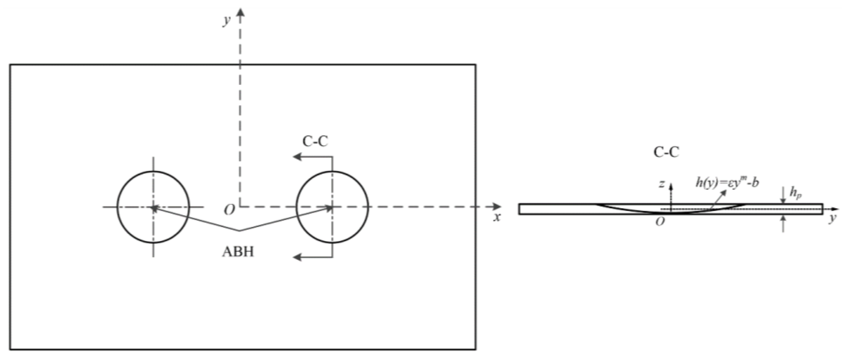
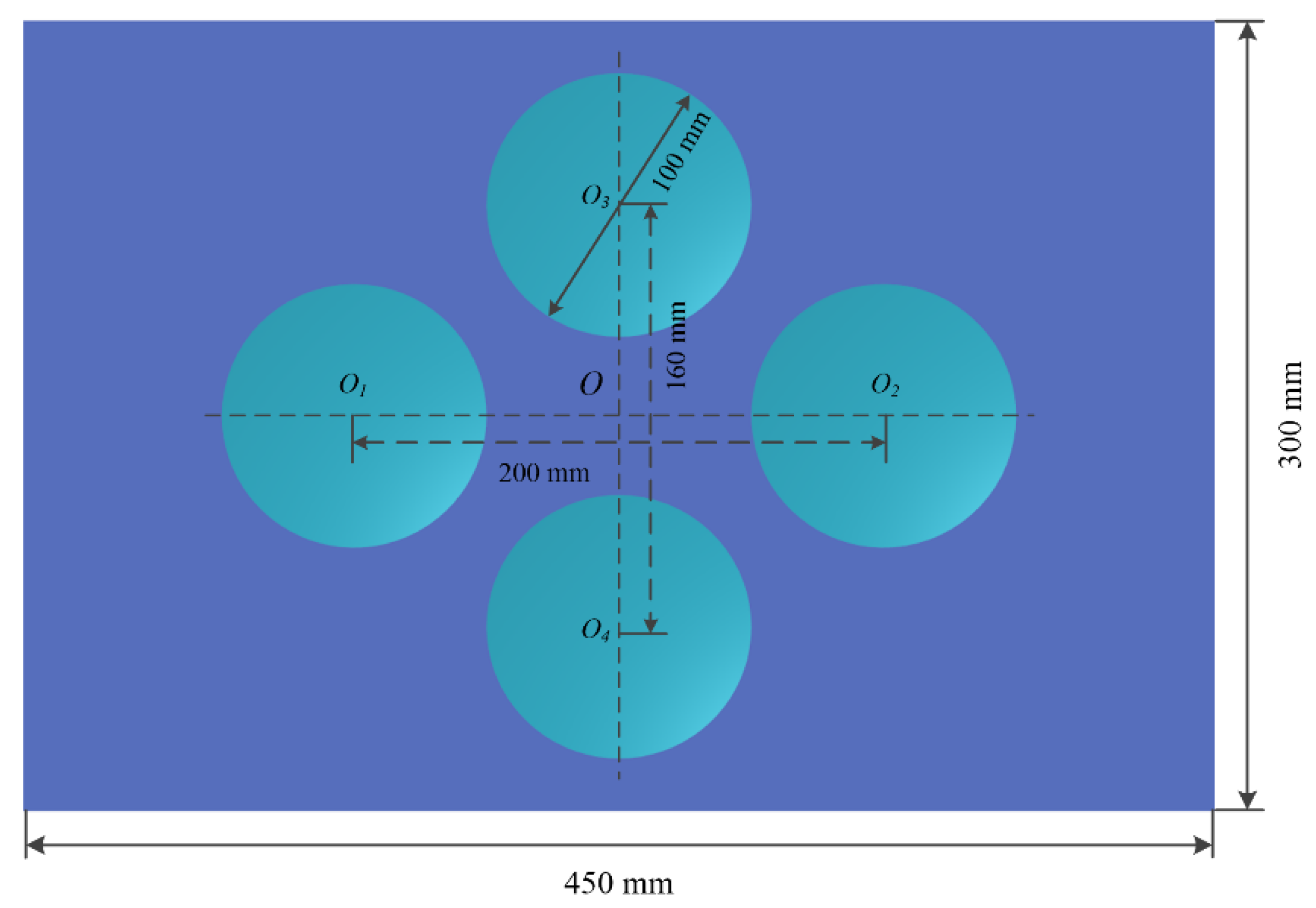
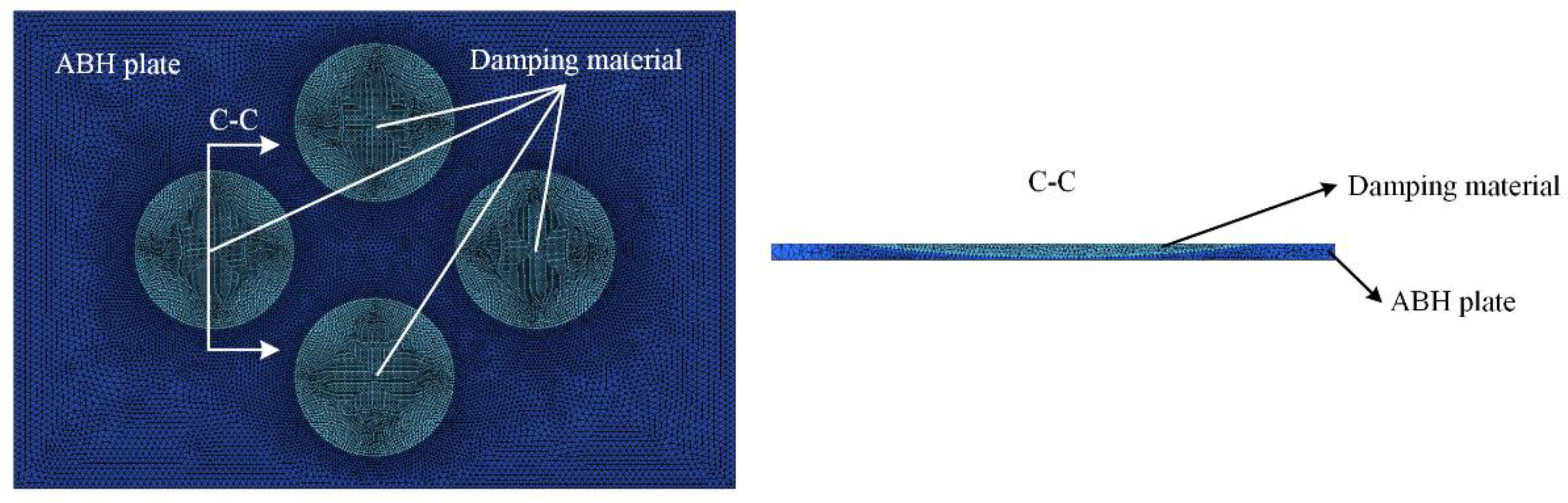
2. Design of the Acoustic Black Hole Plate

A schematic diagram of the structure of a 2D ABH embedded into a rectangular plate is given in Figure 1. The following equation can be used to calculate the thickness of the ABH plate:
h ( y ) = { ε y m b ,   ABH   region h p ,   Uniform   region
where ε is a constant, m is the power exponent of the thickness change of the ABH region, m 2 , b is the distance between the coordinate origin and the centre of the ABH region in the z-axis direction, and hp is the thickness of the uniform region of the ABH plate. However, because the thickness of the end tip location of the acoustic black hole cannot be lowered to zero with a power index greater than 2, there is always a truncation in the real ABH structure. The thickness of the truncated region in the model shown in Figure 1 can be stated as follows
h t = h p 2 b
The speed of propagation of the flexural wave in an isotropic thin plate is as follows [35]:
c B = ( B ω 2 / m ) 1 / 4
where B is the bending stiffness of the ABH plate material, B = E h ( x ) 3 / [ 12 ( 1 ν 2 ) ] , ω is the angular frequency, m is the areal density of the ABH plate, m = ρ m h ( x ) , E is the Young’s modulus of the ABH plate material, ν is the Poisson’s ratio, and ρm is the density of the ABH plate material.
The 2D ABH rectangular plate designed in this paper contained four ABH regions with the same diameter and truncation thickness, as shown in Figure 2. The ABH plate has a length of 450 mm, a width of 300 mm, and a uniform thickness area thickness of 4 mm. For the ABH with the centre of O2 in Figure 2, its thickness equation is h ( y ) = 0.0014 × ( x 80 ) 2 1.5 . According to Equations (1) and (2), the thickness of the truncation is 0.5 mm, and the maximum diameter of the ABH region is 100 mm. The ε, m, and b in the thickness equations of the remaining three ABHs are the same as the thickness equation of the ABH with the centre O2, only the positions of their centre points are different.

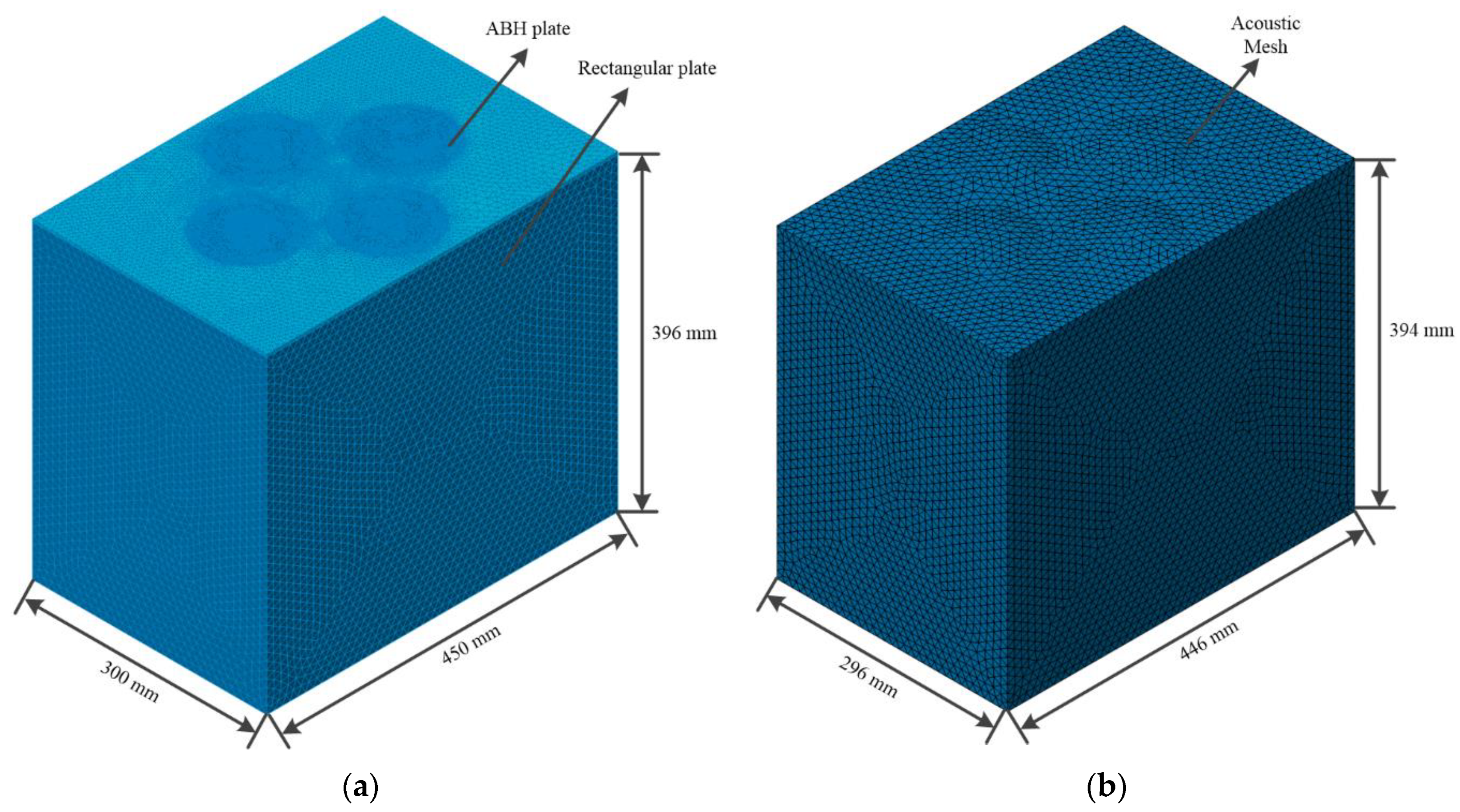
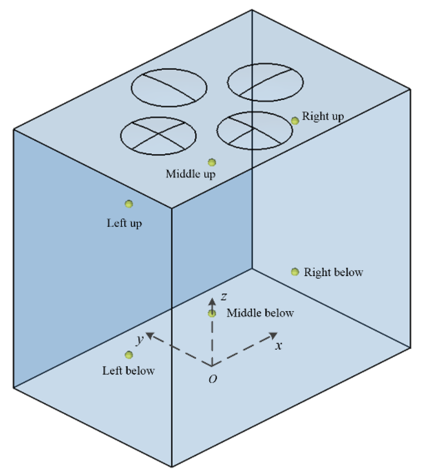
3. Modeling of ABH Plate-Cavity Coupling System

Numerical methods are used to establish a series of models of a rectangular elastic plate-cavity coupling system embedded with 2D ABHs. For a general vibro-acoustic coupling system, the vibro-acoustic coupling equation in matrix form is as follows:
( [ M s 0 A T M f ] · { u · · s p · · } + [ B s 0 0 B f ] · { u · s p · } + [ K s A 0 K f ] ) · { u s p } = { P s P f }
where M is the mass matrix, K is the stiffness matrix, B is the damping matrix, subscript s represents the partitions of the structure, subscript f represents the fluid degrees of freedom, P is the loading vector, u is the freedom degrees of displacements of the structure and pressure, p is the freedom degrees of displacements of the fluid, and [A] is the coupling matrix between the fluid and structure degrees of freedom at the wetted interface.
In the vibro-acoustic coupling calculation, the structural modal participation factor and the acoustic modal participation factor can represent the contribution of the structural modes and the acoustic modes to the vibro-acoustic coupling response, respectively. The structural modal participation factor [ χ s ] and the acoustic modal participation factor [ χ f ] can be calculated by
[ χ s ] = ω 2 [ Φ f ] [ Z 2 ] [ a T ] [ Λ s ]
[ χ f ] = [ Φ f ] [ Λ f ]
where [ Φ f ] are the uncoupled, undamped rigid-walled acoustic modes, [ Λ s ] is a diagonal matrix such that [ Λ s i i ] = q s i , [ Λ f ] is a diagonal matrix such that [ Λ f i i ] = q f i , { q s } is the modal amplitude for the structure, { q f } is the modal amplitude for the fluid, a = Φ s T A Φ f , and [ Φ s ] are the uncoupled, undamped structural mode shapes, and Z2 can be expressed as
[ Z 2 ] = [ ω 2 [ m f ] + i ω [ b f ] + [ k f ] ] 1
where m f = Φ f T M f Φ f , b f = Φ f T B f Φ f , k f = Φ f T K f Φ f .
The closed plate-cavity coupling system was composed of the ABH plate designed in Section 2 and five other rectangular plates with uniform thickness, and the thickness of the uniform rectangular plates were 2 mm. The vibro-acoustic FEM model of the plate-cavity coupling system is shown in Figure 3. The ABH rectangular plate and the acoustic cavity were meshed using the second-order tetrahedral unit C3D10. The uniform region of the ABH plate and five other rectangular plates had a grid size of 4 mm, while the ABH region had a grid size of 2 mm. The mesh in the ABH region’s tiny curved portion was encrypted to provide a seamless transition from small cells to big cells, and the minimum cell size during encryption was 0.1 mm. For the acoustic mesh of the cavity, the side length of the largest element needed to be less than 1/6 of the wavelength corresponding to the highest calculation frequency. The grid size of the acoustic FEM model established in this paper was 10 mm, so the highest acoustic calculation frequency could reach 5 kHz. The material of the plates was 1060 AL, the density was 2710 kg/m3, the Poisson’s ratio was 0.33, the Young’s modulus was 69 GPa, and the damping loss factor was 0.005. The fluid medium in the acoustic cavity was air, the speed of sound in the air was 340 m/s, and the density of the air was 1.225 kg/m3.
In the commercial software LMS Virtual.Lab®, the six inner surfaces of the structural model of the ABH plate-acoustic cavity system are respectively fully coupled to the 6 surfaces of the corresponding acoustic mesh of the cavity to create 6 pairs of vibro-acoustic coupling surfaces, thereby a 2D ABH plate-cavity coupling model is established.

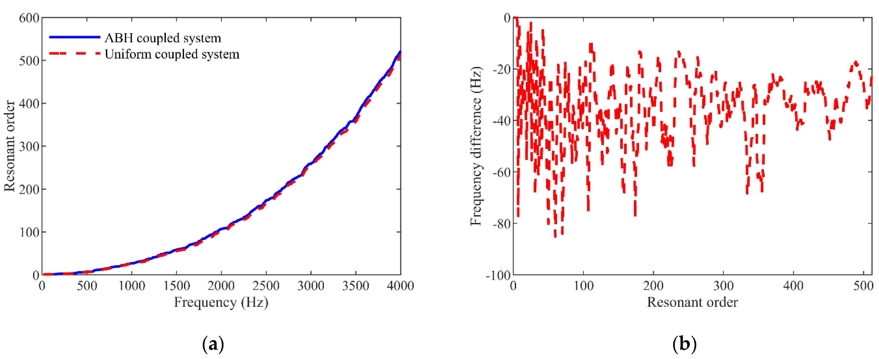
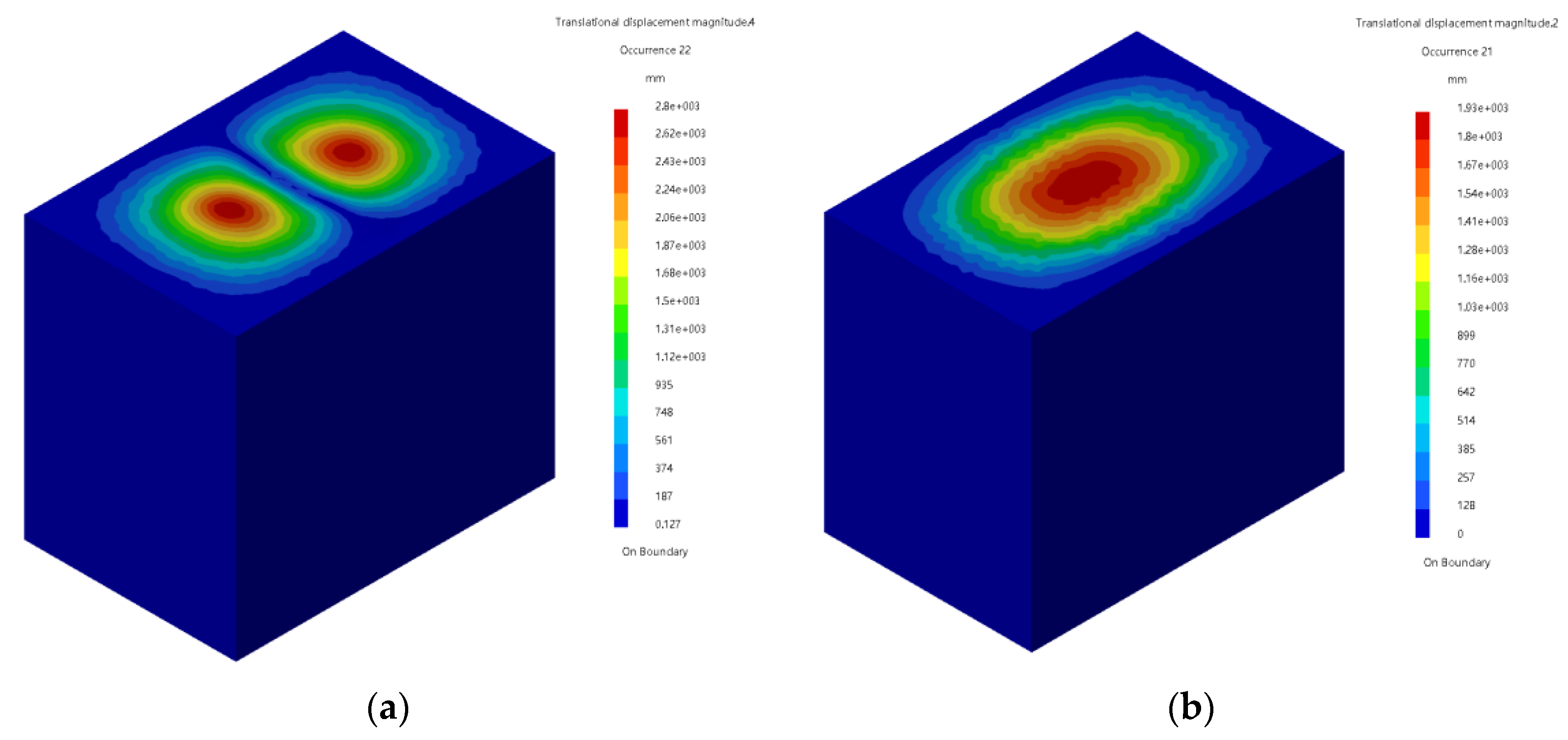
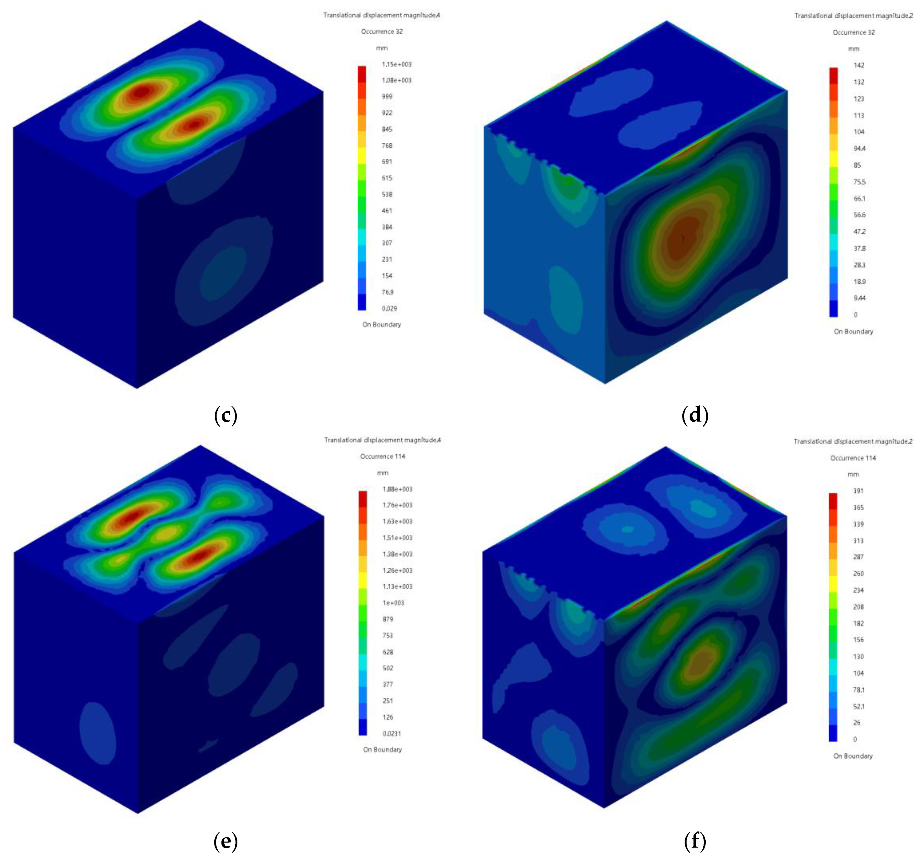
4. Influence of ABHs on Coupling Modes

According to the FEM model of the ABH plate-cavity coupling system established in Section 3, the influence of ABHs on the coupling modes of the ABH coupling system is shown in Figure 4. It can be seen from Figure 4a that below 1 kHz, ABHs have little effect on the orders of the coupling modes and the frequency corresponding to each coupling mode, and in the range of 1 kHz to 5 kHz, the order of the coupling modes of the ABH coupling system are slightly larger than that of the uniform thickness plate-cavity coupling system when the coupling frequencies of these two systems are the same. It can be seen from Figure 4b that in the range of 0 to 500 orders, the coupling mode frequency of the ABH coupling system is less than or equal to the coupling mode frequency of the uniform thickness plate-cavity coupling system when their orders are the same, and the maximum difference is 85.15 Hz.
Figure 5 shows the coupling mode shapes of the ABH coupling system and the uniform thickness plate-cavity coupling system around 800 Hz, 1050 Hz, and 2080 Hz. It can be seen from Figure 5 that at these three frequencies, ABHs have a significant influence on the coupling mode shapes of the coupling system. Around 800 Hz, the number of pitch lines along the longitudinal direction of the rectangular plate of uniform thickness is 1, while the number of pitch lines along the longitudinal direction of the ABH plate is 2. Around 1050 Hz and 2080 Hz, the vibration displacement of the coupling modes of the ABH coupling system mainly occurs on the ABH plate, while for the uniform thickness plate-cavity coupling system it is mainly generated on other rectangular plates, except for the upper plate.

5. Analysis of Vibro-Acoustic Coupling Characteristics

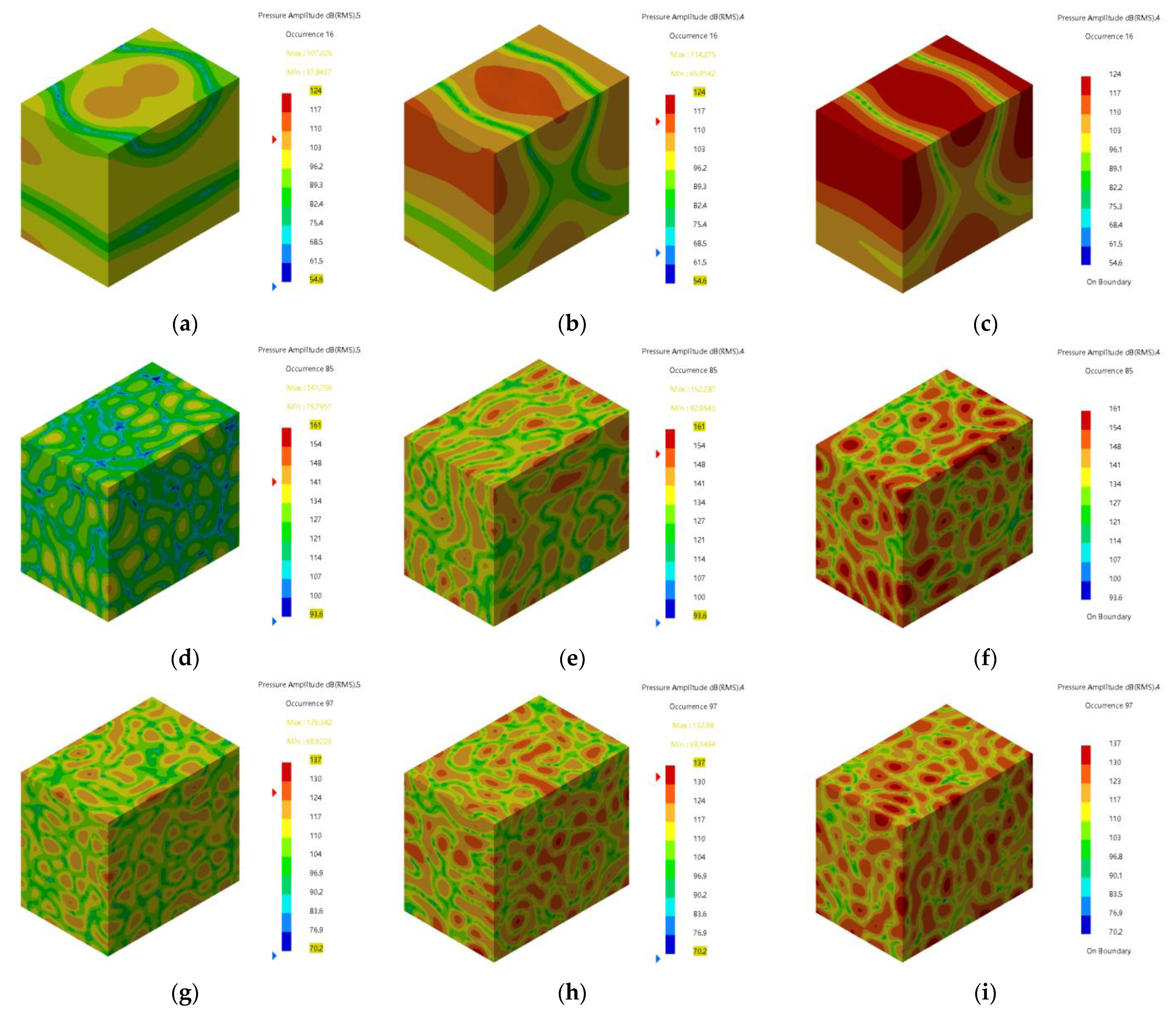
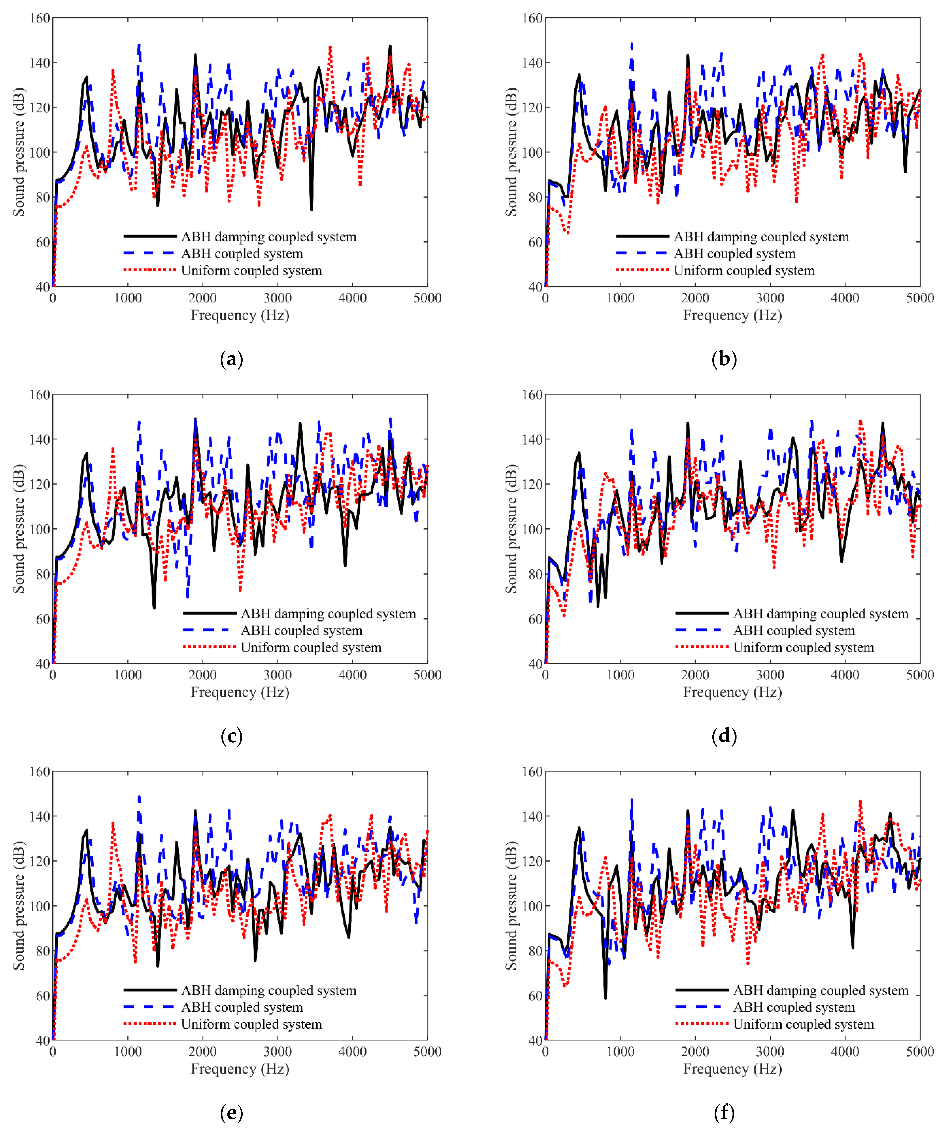
5.1. The Influence of ABHs and Damping Layer on Sound Pressure

The damping material was attached to the four ABH regions, and the damping ABH plate-cavity vibro-acoustic model was established in the LMS Virtual.Lab®. The parameters of the damping material are shown in Table 1, and the FEM model of ABH plate with the damping material is shown in Figure 6. The ABH rectangular plate and the damping layers were meshed using the second-order tetrahedral unit C3D10. The grid size of the uniform region of the ABH plate was 4 mm, and the grid size of the ABH region and the damping layers was 2 mm. The mesh in the small curved area of the ABH region and the damping layers was encrypted to ensure a smooth transition from small cells to large cells, and the minimum cell size was 0.2 mm during encryption. The inner surface of the damping ABH plate model and the five inner surfaces of the shell model established in Section 4 are each fully coupled with the six surfaces of the corresponding acoustic mesh, through which the vibro-acoustic model of the damping ABH plate-cavity is obtained. The influence of ABHs and the damping layers is studied by comprehensively comparing the sound pressure in the acoustic cavity of the damping ABH coupling system, the undamping ABH plate-cavity coupling system, and the uniform thickness plate-cavity coupling system.
Vibro-acoustic coupling calculations were performed on the damping ABH coupling system, the undamping ABH coupling system, and the uniform thickness plate-cavity coupling system to obtain the vibration response of the structure and the acoustic response of the acoustic fields. The acting position of the excitation force was the centre of the outer surface of the ABH plate (for the rectangular plate of uniform thickness, it was the centre of the outer surface of the uniform plate). The amplitude of the excitation force was 10 N, and the frequency started at 1 Hz and ended at 5000 Hz, with a step length of 1 Hz. The calculation frequency of the vibro-acoustic coupling response was 1~5 kHz, and the step length was 50 Hz. The results show that, compared with the uniform thickness plate-cavity coupling system, the damping ABH coupling system and the undamping ABH coupling system could not achieve significant sound suppression effects in the whole calculation frequency band, and only on some certain calculation frequencies, and the sound pressure in their cavities was greatly reduced. From the results of the 101 calculated frequencies, the sound pressure distributions at three frequencies where the ABHs and the damping layer had an obvious effect on the sound pressure suppression are selected, as seen in Figure 7. It can be seen from Figure 7 that at 751 Hz, 4201 Hz, and 4801 Hz, the undamping ABH coupling system had a significant reduction in the maximum sound pressure of the acoustic cavity compared to the uniform thickness plate-cavity coupling system, and the maximum sound pressure of the damping ABH coupling system was further reduced. At 751 Hz, the maximum sound pressure of the undamping ABH coupling system was nearly 10 dB lower than the maximum sound pressure of the uniform-thickness plate-cavity coupling system, while the maximum sound pressure of the damping ABH coupling system was 17 dB lower than that of the uniform-thickness plate-cavity coupling system. At 4201 Hz, the maximum sound pressure of the undamping ABH coupling system was nearly 9 dB lower than the maximum sound pressure of the uniform-thickness plate-cavity coupling system, while the maximum sound pressure of the damping ABH coupling system was 19 dB lower than that of the uniform-thickness plate-cavity coupling system. At 4801Hz, these two values were 4 dB and 10 dB.
To investigate the sound pressure at key positions in the acoustic cavity in the full frequency range of 1 Hz to 5 kHz, six monitoring points were established at the same positions in every acoustic cavity of the three coupling systems, as shown in Figure 8. The origin of the coordinates in Figure 8 is the centre of the outer surface of the bottom rectangular plate. The coordinates of the six monitoring points are as follows: left below (−155, 0, 85), middle below (0, 0, 85), right below (155, 0, 85), left up (−155, 0, 315), middle up (0, 0, 315), and right below (155, 0, 315). The acoustic response of these six monitoring points in 1~5 kHz was obtained through vibro-acoustic coupling calculation so as to study the influence of the ABHs and damping layer on the sound pressure in the acoustic cavity of the coupling systems.
Figure 9 is the spectrum diagram of the sound pressure response of the six monitoring points in the acoustic cavity of the damping ABH coupling system, the undamping ABH coupling system, and the uniform thickness plate-cavity coupling system. It can be seen from Figure 9 that compared with the uniform thickness plate-cavity coupling system, neither the damping ABH coupling system nor the undamping ABH coupling system could reduce the sound pressure in the full frequency range from 1~5 kHz. However, for a certain frequency range and specific frequencies, the damping ABH coupling system and the undamping ABH coupling system could significantly suppress the sound pressure in the acoustic cavity, and in most cases, the suppression effect of the damping ABH coupling system was greater. For the left below and left up monitoring points, the sound pressure of the uniform thickness plate-cavity coupling system was the lowest in 0~700 Hz, and at most frequencies in the range of 1000~3600 Hz, the peak values of the sound pressure of the undamping ABH coupling system was significantly higher than that of the other two coupling systems and the sound pressure of the damping ABH coupling system was not significantly reduced. At most frequencies in the range of 3600~5000 Hz, the damping ABH coupling system could significantly suppress the sound pressure and greatly reduce the peak values. For the left below point, the sound pressure of the damping ABH coupling system at 3701 Hz, 4201 Hz, and 4751 Hz was reduced by 24.2 dB, 15 dB, and 14.2 dB, respectively, compared to that of the uniform thickness plate-cavity coupling system. However, the sound pressure of the left below point of the damping ABH coupling system at 4501 Hz was 4.9 dB higher than that of the uniform thickness plate-cavity coupling system. There was a similar trend for the monitoring points of middle below, middle up, right below, and right up. That is, in the range of 0~700 Hz, the sound pressure of the uniform thickness plate-cavity coupling system was the lowest, and at most frequencies in the range of 1000~3600 Hz, the sound pressure of the damping ABH coupling system was not significantly reduced. At most frequencies in the range of 3600~5000 Hz, the damping ABH coupling system could significantly suppress the sound pressure and greatly reduce the peak values.
Contrasting the undamping ABH plate-cavity coupling system with the damping ABH plate-cavity coupling system, it was found that at most frequencies in 1 kHz to 5 kHz intervals, the sound pressure in the acoustic cavity of the damping ABH plate-cavity coupling system was lower. The above phenomenon shows the significant role of damping layer to suppress sound pressure in the acoustic cavity of the ABH plate-cavity coupling system.

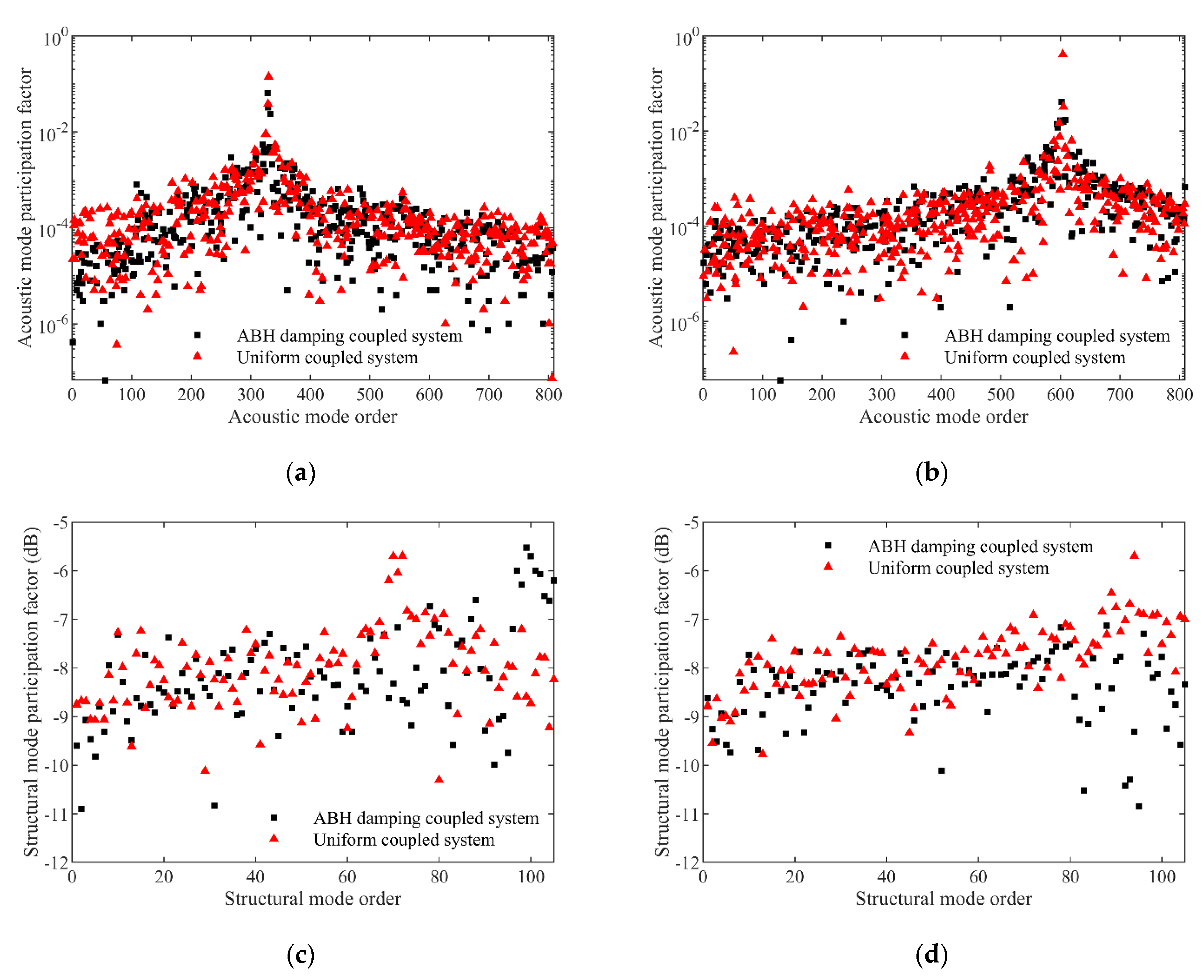
5.2. Mechanism of ABH and Damping Layer

It was found in Figure 9 that compared with the uniform thickness plate cavity coupling system, the sound pressure of the six monitoring points of the damping ABH coupling system was much lower at 3701 Hz, but slightly larger at 4501 Hz. To analyse the mechanism of the action of the ABHs and the damping layer in the above phenomenon, the acoustic modal participation factor and structural modal participation factor of the damping ABH coupling system and uniform thickness plate-cavity coupling system were calculated at 3701 Hz and 4501 Hz, as shown in Figure 10. The structural modal participation factor was expressed in dB, with a reference value of 10. It can be seen from Figure 10 that, whether it was at 3701 Hz or 4501 Hz, the difference of the structural modal participation factor of the damping ABH coupling system and uniform thickness plate-cavity coupling system was not obvious. For the acoustic modal participation factor, it could be concluded that at 4501 Hz, the difference of the structural modal participation factor of the damping ABH coupling system and uniform thickness plate-cavity coupling system was not obvious, while at 3701 Hz, the acoustic modal participation factor of the damping ABH coupling system in the 0~100th order acoustic mode was significantly lower than that of the uniform thickness plate-cavity coupling system. Considering that the shape and size of the acoustic cavities of these two coupling systems were exactly the same, thus the frequency and mode shape of each of their acoustic modes were also exactly the same. At this time, the smaller the acoustic modal participation factor, the smaller the sound pressure of the monitoring points in the corresponding acoustic cavity. Therefore, it can be concluded that the damping ABHs could significantly reduce the participation factor of the acoustic modes within the 100th order of the plate-cavity coupling system, which was the main mechanism for the significant reduction of the sound pressure in the damping ABH coupling system at 3701 Hz.

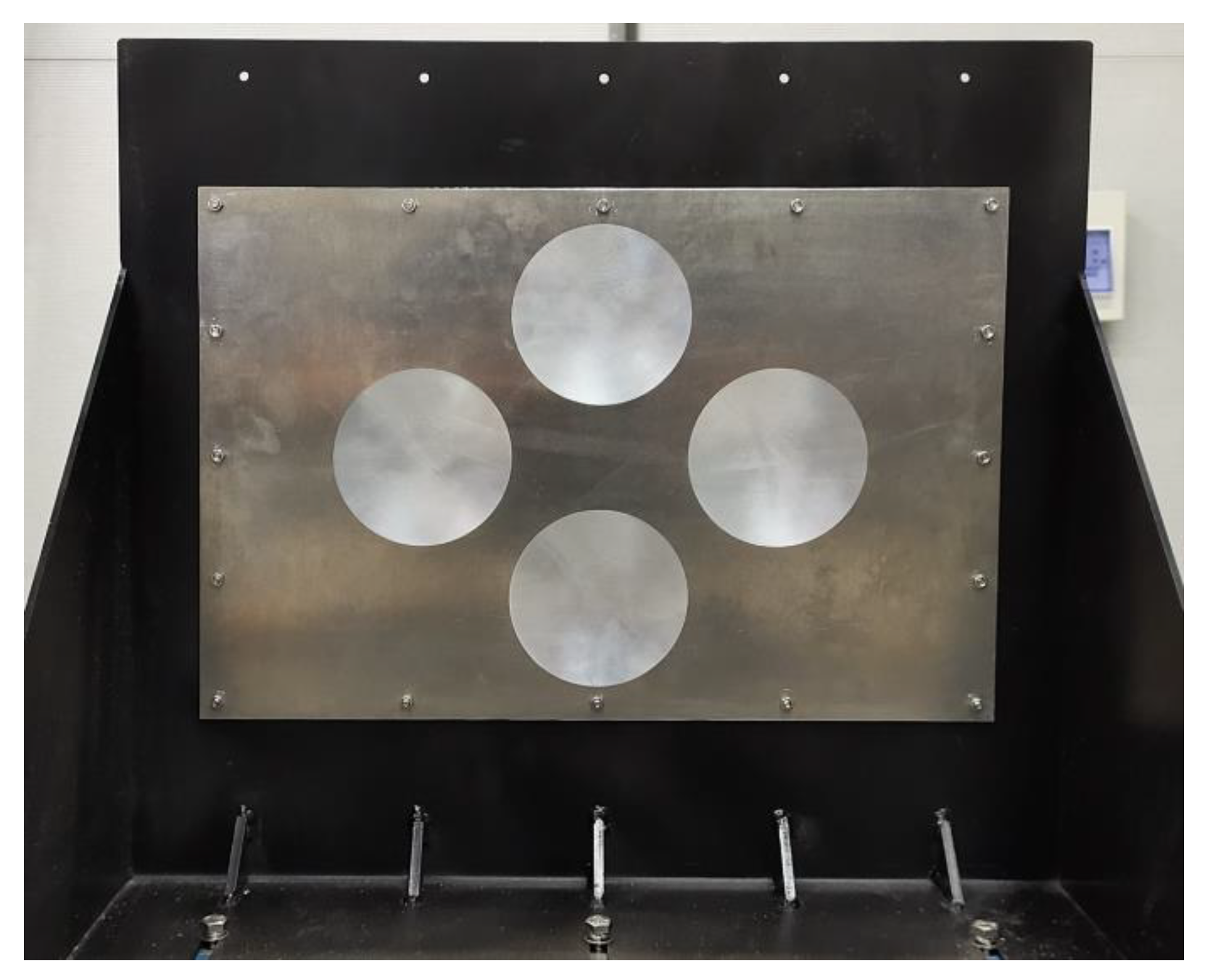
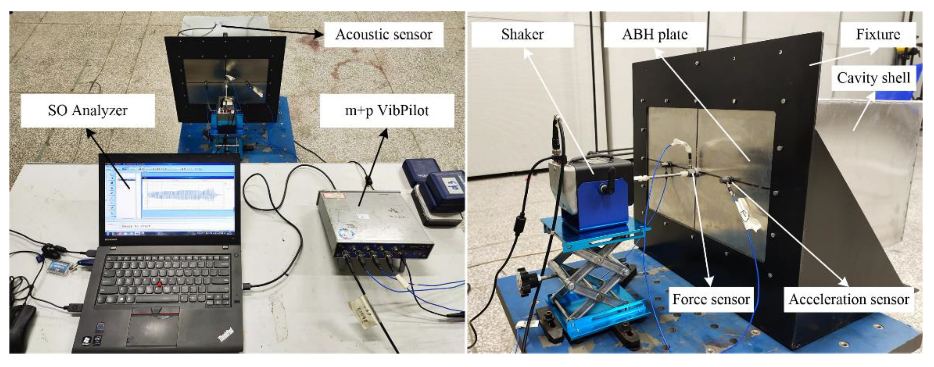
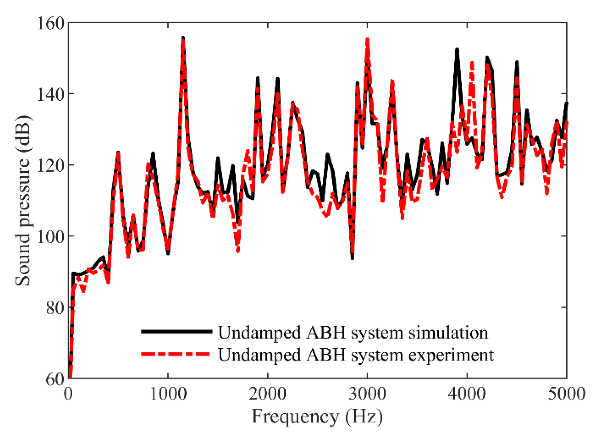
6. Experimental Validation

To carry out the vibro-acoustic experiment of the 2D ABH coupling system, a 2D ABH rectangular plate and an acoustic cavity shell were manufactured. The geometric parameters of the ABH plate and the shell were the same as the model established in Section 4, and the material was 1060AL. Figure 11 shows the physical image of the 2D ABH plate fixed on the fixture. The contact area between the ABH plate and the shell was pasted with acrylic double-sided tape to connect them and prevent sound leakage.
The complete experimental platform of the vibro-acoustic measurement of the 2D ABH coupling system is shown in Figure 12. Both the shaker and the fixture are fixed on the blue platform below. The m + p VibPilot generates a sinusoidal sweep signal and drives the shaker to act on the 2D ABH plate. The acoustic sensor, acceleration sensors, and force sensor are all connected to m + p VibPilot. The amplitude of the excitation force is 10 N, and the frequency is 0~5 kHz. The position of the excitation force is the centre of the ABH plate (based on the coordinate system in Figure 8, the coordinate of the point of excitation force is (0, 0, 400)). The end of the shaker is connected with a force sensor and a magnetic base, and the magnetic base is pasted on the surface of the ABH plate with 502 glue. An acoustic sensor is placed inside the acoustic cavity. The acoustic sensor is located in the exact centre of the acoustic cavity and its position coordinate is (0, 0, 199). The surface of the ABH plate is also pasted with two acceleration sensors to measure the vibration of the ABH plate. VibPilot can collect the time-domain signals measured by the sensors and send the signals to the laptop computer for data processing using SO Analyser software.
The sound pressure spectrum at the monitoring point (0, 0, 199) was calculated by numerical simulation, and the sound pressure spectrum at the same position measured in the experiment was compared with the simulation result, as shown in Figure 13. It can be seen from Figure 13 that for the undamping ABH coupling system in the range of 0~5 kHz, most of the frequencies where the sound pressures of the numerical simulation results and the experimental measurement results appeared as peaks were in good agreement, and the peak amplitude deviation of the sound pressure of these two results was small. Therefore, the accuracy of the FEM vibro-acoustic models of the 2D ABH coupling systems established in this paper and the numerical simulation calculation were proven by experiments.

7. Conclusions

In this study, a 2D ABH rectangular plate was designed and the 2D ABH plate-cavity parallelepiped coupling system was constructed using a 2D ABH plate and five rectangular elastic plates of uniform thickness. To investigate the influence of ABHs on coupling modes of the coupling system, the vibro-acoustic coupling characteristics and mechanism of ABHs and damping layer, a series of vibro-acoustic coupling models of a rectangular elastic coupling system embedded with 2D ABHs were established and a vibro-acoustic simulation was carried out. It has been shown that at most frequencies in the range of 3600~5000 Hz, the damping ABH coupling system could significantly suppress the sound pressure and greatly reduce the peak values. To analyze the mechanism of action of the ABHs and the damping layer, the acoustic modal participation factor and structural modal participation factor of the damping ABH coupling system and uniform thickness plate-cavity coupling system were calculated, and it can be concluded that the significant reduction of the participation factor of the acoustic modes within the 100th order of the coupling system was the main mechanism for the obvious suppression of the sound pressure in the damping ABH coupling system at 3701 Hz. An experimental platform of vibro-acoustic measurement of the 2D ABH coupling system was constructed and the accuracy of the FEM vibro-acoustic models of the 2D ABH coupling systems established in this paper and the numerical simulation calculation have been proven by vibro-acoustic measurement experiments. The research results of this paper could provide guidance and assistance to the noise reduction design of cabs of automobile and engineering machinery in practice.

Author Contributions

Conceptualization, X.D.; methodology, X.D.; software, X.D.; validation, X.D. and Q.F.; formal analysis, X.D.; investigation, X.D.; writing—original draft preparation, X.D.; writing—review and editing, X.D., X.L. and C.Z. All authors have read and agreed to the published version of the manuscript.

Funding

This research was funded by the National Key Research and Development Program of China (grant number 2019YFB2006402) and the Scientific Research Foundation for High-Level Talents of Nanjing Institute of Technology (grant number YKJ202102).

Institutional Review Board Statement

Not applicable.

Informed Consent Statement

Not applicable.

Data Availability Statement

Not applicable.

Conflicts of Interest

The authors declare no conflict of interest.

References

  1. Ji, H.; Han, B.; Cheng, L.; Inman, D.J.; Qiu, J. Frequency attenuation band with low vibration transmission in a finite-size plate strip embedded with 2D acoustic black holes. Mech. Syst. Signal. Processing 2022, 163, 108149. [Google Scholar] [CrossRef]
  2. Gao, N.; Guo, X.; Deng, J.; Cheng, B.; Hou, H. Elastic wave modulation of double-leaf ABH beam embedded mass oscillator. Appl. Acoust. 2021, 173, 107694. [Google Scholar] [CrossRef]
  3. Pelat, A.; Gautier, F.; Conlon, S.C.; Semperlotti, F. The acoustic black hole: A review of theory and applications. J. Sound Vib. 2020, 476, 115316. [Google Scholar] [CrossRef]
  4. Bowyer, E.; Krylov, V.V. Damping of flexural vibrations in turbofan blades using the acoustic black hole effect. Appl. Acoust. 2014, 76, 359–365. [Google Scholar] [CrossRef] [Green Version]
  5. Wang, X.; Qin, Y.; Ji, H. Broadband noise reduction inside helicopter cockpit with acoustic black hole effect. Acta Aeronaut. Et Astronaut. Sin. 2020, 41, 228–238. [Google Scholar] [CrossRef]
  6. Du, X.F.; Huang, D.C.; Zhang, J.R. Dynamic Property Investigation of Sandwich Acoustic Black Hole Beam with Clamped-Free Boundary Condition. Shock Vib. 2019, 2019, 6708138. [Google Scholar] [CrossRef] [Green Version]
  7. Krylov, V.V. Overview of localised flexural waves in wedges of power-law profile and comments on their relationship with the acoustic black hole effect. J. Sound Vib. 2020, 468, 115100. [Google Scholar] [CrossRef] [Green Version]
  8. Krylov, V.V. Conditions for validity of the geometrical-acoustics approximation in application to waves in an acute-angle solid wedge. Sov. Phys. Acoust. Ussr 1989, 35, 176–180. [Google Scholar]
  9. Krylov, V.V.; Tilman, F. Acoustic ‘black holes’ for flexural waves as effective vibration dampers. J. Sound Vib. 2004, 274, 605–619. [Google Scholar] [CrossRef]
  10. Krylov, V.V.; Winward, R. Experimental investigation of the acoustic black hole effect for flexural waves in tapered plates. J. Sound Vib. 2007, 300, 43–49. [Google Scholar] [CrossRef] [Green Version]
  11. Gao, N.; Wei, Z.; Zhang, R.; Hou, H. Low-frequency elastic wave attenuation in a composite acoustic black hole beam. Appl. Acoust. 2019, 154, 68–76. [Google Scholar] [CrossRef]
  12. Tang, L.; Cheng, L.; Ji, H.; Qiu, J. Characterization of acoustic black hole effect using a one-dimensional fully-coupled and wavelet-decomposed semi-analytical model. J. Sound Vib. 2016, 374, 172–184. [Google Scholar] [CrossRef]
  13. Fu, Q.; Du, X.; Wu, J.; Zhang, J. Dynamic property investigation of segmented acoustic black hole beam with different power-law thicknesses. Smart Mater. Struct. 2021, 30, 055001. [Google Scholar] [CrossRef]
  14. Zhao, C.; Prasad, M.G. Acoustic Black Holes in Structural Design for Vibration and Noise Control. Acoustics 2019, 1, 220–251. [Google Scholar] [CrossRef] [Green Version]
  15. Bowyer, E.P.; Krylov, V.V. A review of experimental investigations into the acoustic black hole effect and its applications for reduction of flexural vibrations and structure-borne sound. In Proceedings of the 44th International Congress and Exposition on Noise Control Engineering, INTER-NOISE, San Francisco, CA, USA, 9–12 August 2015. [Google Scholar]
  16. Feurtado, P.A.; Conlon, S.C. An experimental investigation of acoustic black hole dynamics at low, mid, and high frequencies. J. Vib. Acoust. 2016, 138, 61002. [Google Scholar] [CrossRef]
  17. Feurtado, P.A.; Conlon, S.C. Transmission loss of plates with embedded acoustic black holes. J. Acoust. Soc. Am. 2017, 142, 1390–1398. [Google Scholar] [CrossRef]
  18. Feurtado, P.A.; Conlon, S.C. Wavenumber transform analysis for acoustic black hole design. J. Acoust. Soc. Am. 2016, 140, 718–727. [Google Scholar] [CrossRef]
  19. Ma, L.; Cheng, L. Sound radiation and transonic boundaries of a plate with an acoustic black hole. J. Acoust. Soc. Am. 2019, 145, 164–172. [Google Scholar] [CrossRef]
  20. Ma, L.; Cheng, L. Topological optimization of damping layout for minimized sound radiation of an acoustic black hole plate. J. Sound Vib. 2019, 458, 349–364. [Google Scholar] [CrossRef]
  21. Li, X.; Ding, Q. Sound radiation of a beam with a wedge-shaped edge embedding acoustic black hole feature. J. Sound Vib. 2019, 439, 287–299. [Google Scholar] [CrossRef]
  22. Ji, H.; Wang, X.; Qiu, J.; Cheng, L.; Wu, Y.; Zhang, C. Noise reduction inside a cavity coupled to a flexible plate with embedded 2-D acoustic black holes. J. Sound Vib. 2019, 455, 324–338. [Google Scholar] [CrossRef]
  23. Wang, X.; Ji, H.; Qiu, J.; Cheng, L. Wavenumber domain analyses of vibro-acoustic decoupling and noise attenuation in a plate-cavity system enclosed by an acoustic black hole plate. J. Acoust. Soc. Am. 2019, 146, 72–84. [Google Scholar] [CrossRef] [PubMed] [Green Version]
  24. Deng, J.; Guasch, O.; Maxit, L.; Zheng, L. Transmission loss of plates with multiple embedded acoustic black holes using statistical modal energy distribution analysis. Mech. Syst. Signal. Processing 2021, 150, 107262. [Google Scholar] [CrossRef]
  25. Deng, J.; Guasch, O.; Maxit, L.; Zheng, L. Annular acoustic black holes to reduce sound radiation from cylindrical shells. Mech. Syst. Signal. Processing 2021, 158, 107722. [Google Scholar] [CrossRef]
  26. Tang, L.; Cheng, L. Impaired sound radiation in plates with periodic tunneled Acoustic Black Holes. Mech. Syst. Signal. Processing 2020, 135, 106410. [Google Scholar] [CrossRef]
  27. Conlon, S.C.; Fahnline, J.B.; Semperlotti, F. Numerical analysis of the vibroacoustic properties of plates with embedded grids of acoustic black holes. J. Acoust. Soc. Am. 2015, 137, 447–457. [Google Scholar] [CrossRef] [PubMed]
  28. Du, X.; Huang, D.; Fu, Q.; Zhang, J. Effects of acoustic black hole parameters and damping layer on sound insulation performance of abh circular plate. Appl. Sci. 2019, 9, 5366. [Google Scholar] [CrossRef] [Green Version]
  29. Zhang, H.; Shi, D.; Zha, S.; Wang, Q. Vibro-acoustic analysis of the thin laminated rectangular plate-cavity coupling system. Compos. Struct. 2018, 189, 570–585. [Google Scholar] [CrossRef]
  30. Xue, F.; Sun, B. Modelling and analysis of global vibroacoustic coupling characteristics of a rectangular enclosure bounded by a flexible panel. Shock Vib. 2018, 2018, 7562630. [Google Scholar] [CrossRef]
  31. Pan, J.; Bies, D.A. The effect of fluid–structural coupling on sound waves in an enclosure—theoretical part. J. Acoust. Soc. Am. 1990, 87, 691–707. [Google Scholar] [CrossRef]
  32. Du, J.T.; Li, W.L.; Xu, H.A.; Liu, Z.G. Vibro-acoustic analysis of a rectangular cavity bounded by a flexible panel with elastically restrained edges. J. Acoust. Soc. Am. 2012, 131, 2799–2810. [Google Scholar] [CrossRef] [PubMed]
  33. Zaitsev, V.; Sas, P. Nonlinear response of a weakly damaged metal sample: A dissipative modulation mechanism of vibro-acoustic interaction. J. Vib. Control. 2000, 6, 803–822. [Google Scholar] [CrossRef]
  34. Li, Y.; Cheng, L. Vibro-acoustic analysis of a rectangular-like cavity with a tilted wall. Appl. Acoust. 2007, 68, 739–751. [Google Scholar] [CrossRef]
  35. Du, X.; Fu, Q.; Zhang, J.; Zong, C. Numerical and Experimental Study on Suppression Effect of Acoustic Black Hole on Vibration Transmission of Refrigerator Compressor. Appl. Sci. 2021, 11, 8622. [Google Scholar] [CrossRef]
Figure 1. Schematic diagram of a rectangular plate embedded with 2D ABH.
Applsci 12 04097 g001
Figure 2. The geometric parameters of the proposed ABH plate.
Applsci 12 04097 g002
Figure 3. A 2D ABH plate-cavity coupling FEM model: (a) structural FEM model and (b) acoustic FEM model.
Applsci 12 04097 g003
Figure 4. Comparison of the coupling modes of the ABH plate-cavity coupling system and the uniform thickness plate-cavity coupling system: (a) relationship between coupling mode orders and frequencies and (b) differences of the coupling mode frequencies of these two systems.
Applsci 12 04097 g004
Figure 5. The influence of ABHs on coupling modes: (a) coupling mode of the ABH coupling system at 773 Hz; (b) coupling mode of the uniform plate-cavity coupling system at 805 Hz; (c) coupling mode of the ABH coupling system at 1035 Hz; (d) coupling mode of the uniform plate-cavity coupling system at 1051 Hz; (e) coupling mode of the ABH coupling system at 2075 Hz; (f) coupling mode of the uniform plate-cavity coupling system at 2085 Hz.
Applsci 12 04097 g005aApplsci 12 04097 g005b
Figure 6. FEM model of the damping ABH plate.
Applsci 12 04097 g006
Figure 7. The sound pressure distribution of damping ABH, undamping ABH, uniform thickness plate-cavity coupling system: (a) damping ABH coupling system at 751 Hz; (b) undamping ABH coupling system at 751 Hz; (c) uniform thickness ABH coupling system at 751 Hz; (d) damping ABH coupling system at 4201 Hz; (e) undamping ABH coupling system at 4201 Hz; (f) uniform thickness coupling system at 4201 Hz; (g) damping ABH coupling system at 4801 Hz; (h) undamping ABH coupling system at 4801 Hz; and (i) uniform thickness ABH coupling system at 4801 Hz.
Applsci 12 04097 g007
Figure 8. Schematic diagram of the monitoring point locations.
Applsci 12 04097 g008
Figure 9. Spectrogram of the sound pressure of the monitoring points: (a) sound pressure of left below, (b) sound pressure of left up, (c) sound pressure of middle below, (d) sound pressure of middle up, (e) sound pressure of right below, and (f) sound pressure of right up.
Applsci 12 04097 g009
Figure 10. Acoustic modal participation factor and structural modal participation factor of the damping ABH coupling system and the uniform thickness plate-cavity coupling system: (a) acoustic modal participation factor at 3701 Hz; (b) acoustic modal participation factor at 4501 Hz; (c) structural modal participation factor at 3701 Hz; (d) structural modal participation factor at 4501 Hz.
Applsci 12 04097 g010
Figure 11. Physical image of the 2D ABH rectangular plate.
Applsci 12 04097 g011
Figure 12. Experimental platform of vibro-acoustic measurement of the 2D ABH coupling system.
Applsci 12 04097 g012
Figure 13. Comparison of the simulation results and experimental results of the sound pressure of the 2D ABH plate-cavity coupling system.
Applsci 12 04097 g013
Table 1. Damping material properties.
MaterialDensity (kg/m3)Young’s Modulus (Pa)Poisson’s RatioLoss Factor
Viscoelastic material18129 × 1060.450.2
Publisher’s Note: MDPI stays neutral with regard to jurisdictional claims in published maps and institutional affiliations.

