
Full-Parallax Multiview Generation with High-Speed Wide-Angle Dual-Axis Scanning Optics

School of Electronic and Electrical Engineering, Kyungpook National University, 80 Daehak-ro, Buk-gu, Daegu 41566, Korea
*
Author to whom correspondence should be addressed.
Appl. Sci. 2022, 12(9), 4615; https://0-doi-org.brum.beds.ac.uk/10.3390/app12094615
Submission received: 30 March 2022
/
Revised: 29 April 2022
/
Accepted: 30 April 2022
/
Published: 4 May 2022
(This article belongs to the Special Issue Holography, 3D Imaging and 3D Display Volume II)
Abstract
:Three-dimensional displays are receiving considerable attention owing to their ability to deliver realistic content. Particularly, a multiview display with temporal multiplexing offers advantages in terms of fewer restrictions for optical alignment and flexibility in forming view density. However, most of studies realize horizontal parallax-only multiview display. In a horizontal parallax-only multiview display the content is distorted in the vertical direction as the observer changes the viewing distance. It is helpful to understand this phenomenon using the Wigner distribution function (WDF). In this study, we divided the viewing zone (VZ) into the sub-viewing zone and integrated viewing zone according to the number of views of the observer. Specifically, the changes in the contents are experimentally evaluated at different viewing distances to validate our expectation. For the experiment, we implemented a full-parallax multiview display with spherical symmetry and designed a high-speed wide-angle dual-axis scanner. This scanner comprises two single-axis scanners connected by high numerical-aperture scanning optics. The proposed system and WDF analysis of VZ will be helpful to evaluate the characteristics of the multiview system.
1. Introduction
Three-dimensional (3D) displays are being actively studied actively owing to their ability to provide immersive content with 3D depth information [1,2,3]. Among them, a multiview display is a promising method for reconstructing 3D content that generates plural views according to the viewing direction [4]. The spatial multiplexing method [5,6,7] and temporal multiplexing method [8,9,10,11,12] are typically used for creating plural views in multiview displays. In particular, the multiview display using temporal multiplexing imposes fewer restrictions on optical alignments compared to the method using spatial multiplexing. Moreover, it is possible to change the number of views and the view density based on requirements.
Multiview displays require a sufficient view density to provide a natural view-image change when the viewpoint of the observer changes. The area where 3D contents are fully observed without vignetting is called a viewing zone (VZ) [13,14]. In a multiview display with full-parallax, 3D contents are observed correctly independent of the position of the viewer within the VZ. By contrast, in a multiview display with only horizontal parallax, the 3D contents are distorted as the viewpoint of the observer moves along the longitudinal axis direction [15,16]. To understand this phenomenon, the VZ needs to be interpreted using the WDF [17,18,19].
The time-multiplexing method in multiview displays is typically realized using an optical scanner, which is important to determine the performance of the multiview display, such as viewing angle, view volume, and frame rate [20]. To realize a full-parallax multiview display, the optical scanner must be capable of deflecting view information in two axes. This can be achieved using the optical cross-connected technology (OXCT) scanner owing to its large scanning angle and a relatively large beam diameter. In the OXCT, two individual scanners are arranged sequentially. Therefore, OXCT scanners have a pincushion error resulting from the gap between the two rotation axes [21,22].
In this study, we propose a display in which a full-parallax image is formed inside a ball lens with spherical symmetry. The proposed display provides undistorted content regardless of change in the observer viewing distance within the VZ. We analyzed the observation characteristics within the VZ using WDF. The obtained results were consistent with the experimental results. This system was implemented by designing a high-speed wide-angle dual-axis scanner comprising two different single-axis scanners, namely a resonance scanner and galvanometer scanner. The former is driven at 240 Hz with a 60-degree maximum optical scanning angle and rotates an image around the horizontal axis, whereas the latter is driven at 12 Hz with an 80-degree maximum optical scanning angle and rotates an image around the vertical axis. The two scanners are connected by scanning optics with a high numerical aperture (NA) and their two rotation axes are effectively placed on the common plane.
2. Interpretation of the VZ Using WDF
In a multiview display, a VZ is an area where 3D contents are fully observed without vignetting. To understand the properties of the VZ, it is necessary to divide the VZ into a sub-viewing zone (SVZ) for an individual view and integrated viewing zone (IVZ) for an integrated view. In the IVZ, several views are observed simultaneously, but each view is vignetted due to the limitation in the aperture size of the observation. The extent of vignetting changes according to the relative position of the observation with respect to the SVZ. Therefore, the WDF analysis is useful for estimating the integrated view because both the space and spatial frequency are considered.
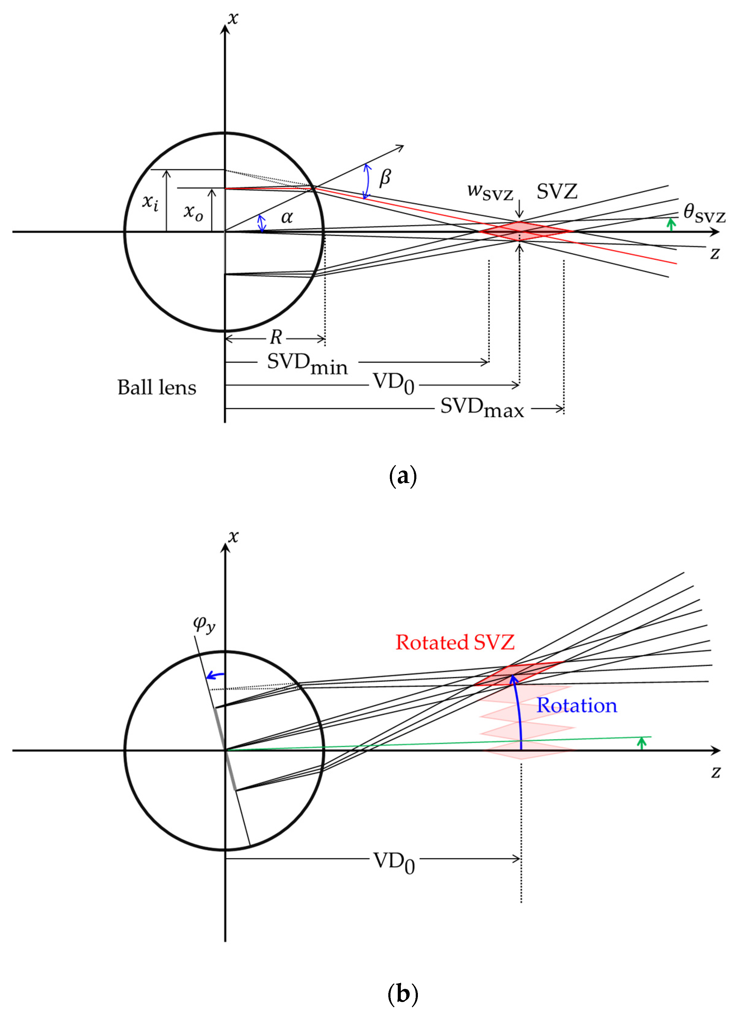
Considering optical structure of the system is necessary to use WDF analysis for integrated views. Figure 1 shows a schematic of the proposed system. Our proposed system has a ball lens which is employed as the optical component for generating SVZ. Therefore, the analysis is performed on the ball lens. The viewing distance of a 3D display is typically described using ray-optics-based analysis [23]. Figure 2 depicts the definition of viewing distance range and width of the SVZ when the image is projected inside a ball lens. So, ray-optics-based analysis is performed on the ball lens. The optical ray from the image is refracted at the surface of the ball lens and the collimated rays are focused on a point. The distance from the center of the ball lens to the point of focus is called the reference viewing distance and it is calculated as
Here, is the radius of the ball lens and is the position on the image plane. and are the incident and refracted angles, respectively, at the surface of the ball lens. These angles are related by Snell’s law, , where is the refractive index of the ball lens.
The viewing distance is limited by the field of view, , which is determined by the optical stop in the 4-f structure positioned before the optical scanner. The viewing distance has a distance range, and the minimum and maximum viewing distances are determined based on half of the field of view [24]. The distance range is obtained using Snell’s law in the same manner as that of the viewing distance. Therefore, the minimum and maximum viewing distances of SVZ are, respectively, expressed as
The viewing distance range of SVZ increases as the field of view increases. The width of SVZ is directly related to the field of view and is approximately the same as the arc length; it is determined as
When an image is observed within the SVZ, the height of the virtual image, , becomes higher than the initial position, , and it can be derived using backtracking from the viewing distance to the center of the ball lens. It is obtained as
To generate multiple views in the proposed system, each SVZ is placed next to each other in a circle with a radius equal to the reference viewing distance. The position of SVZ is changed by angle around the y-axis, where is the rotation angle of the image at the center of the ball lens. It is slightly smaller than the optical scanning angle of the dual-axis scanner because the image at the scanner is enlarged via magnifying optics. The number of views in the system is determined using the maximum rotation angle and the field of view of SVZ, , as
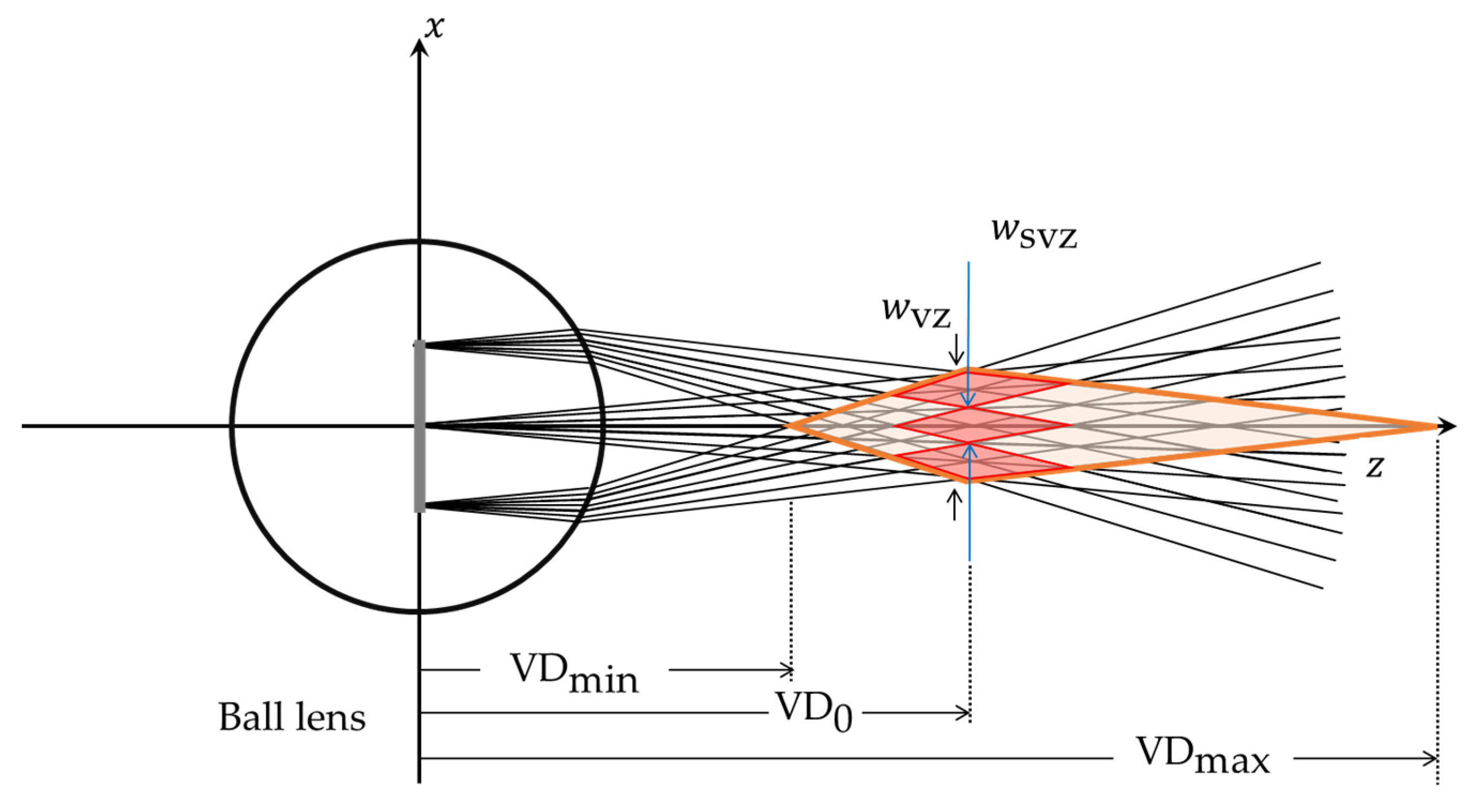
Figure 3 depicts the formation of a VZ from SVZs. Because the observer can watch the view integrated from different views outside of the SVZ, the area of VZ exceeds the summation of all SVZs. The width of the VZ is expressed as follows
By contrast, the viewing range along the longitudinal direction becomes enlarged. The minimum and maximum viewing distance are given by
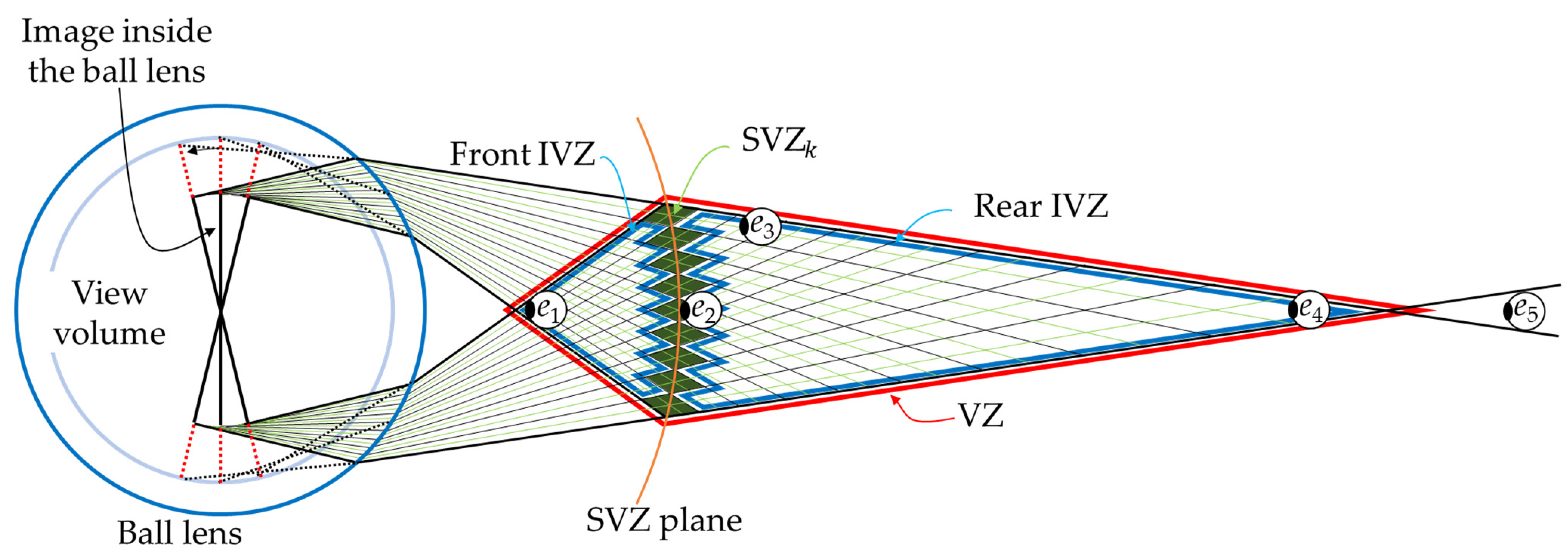
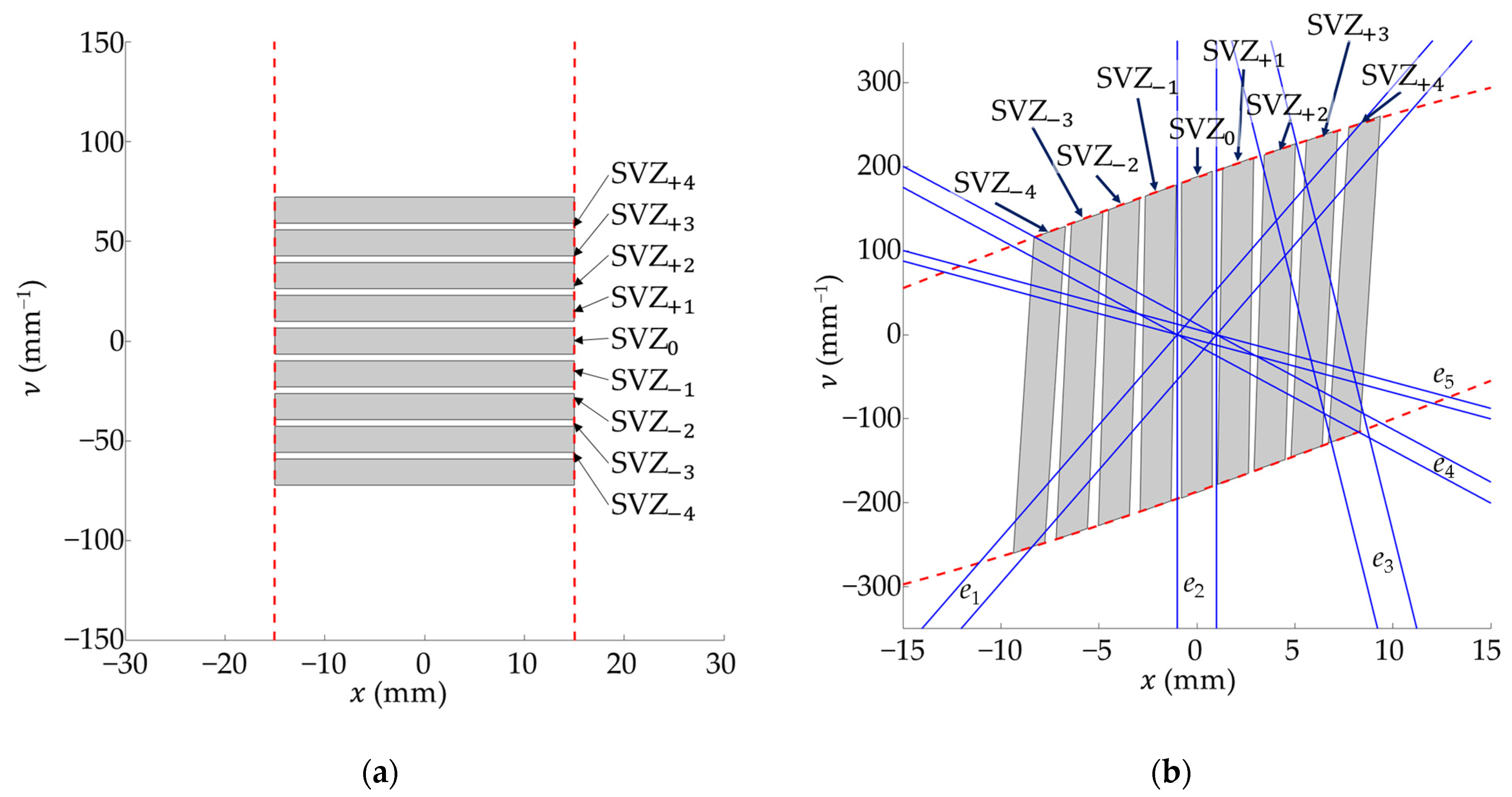
Figure 4 shows the front and rear IVZs for the integrated view and nine SVZs for individual views. The front and rear IVZs are separated by a set of SVZs. The SVZ is the area defined by a single view and the IVZ is the area outside of SVZ. Even though each view is vignetted in the IVZ, multiple vignetted views in the IVZ are overlapped with each other in the SVZ, and the entire scene is integrated. In Figure 4, five eye positions for observation are indicated by ~. The properties of IVZ are investigated using WDF, which represents space and spatial frequency information visually [25,26,27]. The general definition of WDF, is
where denotes the complex conjugate; and are spatial coordinates and are the spatial–frequency coordinates.
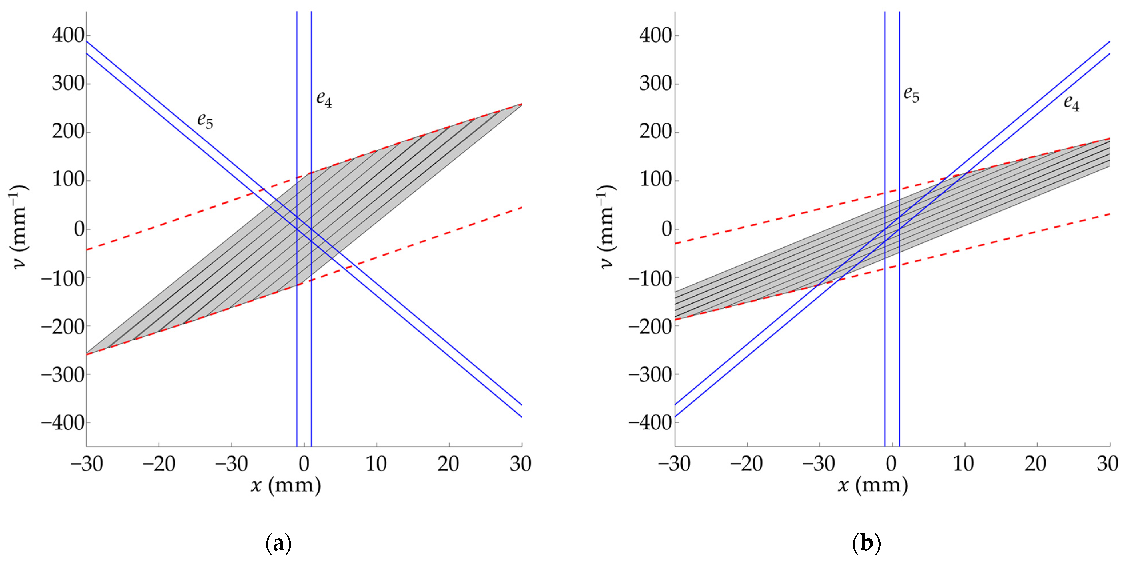
The WDF analysis is performed using MATLAB (MathWorks). Figure 5 depicts the WDF analysis of the observations based on five eye positions. Figure 5a shows an initial WDF of nine views assigned to SVZs inside the ball lens, where indicates the WDF of the view assigned to the SVZ located on the optical axis. The SVZs are numbered according to the rotation angle. Accordingly, as the rotation angle increases, the number of the corresponding also increases. As the WDFs of the whole views are stacked along the spatial frequency , each view provides the information in a different direction. In the plots, the red dashed lines represent the size of the image inside the ball lens.
Figure 5b shows the change in WDF at the reference viewing distance; the WDF of the observations based on five different eye positions are indicated by blue lines. These five eye positions are indicated in Figure 4. Here, the red dashed lines represent the boundaries transformed from those in Figure 5a. Because the reference viewing distance is approximately equal to the focal plane, the WDFs of the views are stacked horizontally. The second eye position, , is placed on the SVZ plane, and the WDF of the observation covers the entire range of . This implies that at the second eye position, the entire single view can be observed. The upper and lower limits of the blue lines are not indicated because the field of view of the human eye is large and extends beyond the range of this plot. At the third eye position, , three views corresponding to , , and can be observed. Furthermore, the WDF of the third eye position indicated by the blue lines contains the upper portion of , middle portion of , and lower portion of . Consequently, three views are vignetted at the third eye position and their integrated view is observed. The first and fourth eye positions and are located at the apexes of the front and rear IVZs, respectively. Their WDF partially contains all nine views. Therefore, the integrated views obtained from nine vignetted views are observed. Although the fifth eye position is located outside of VZ, the view is observed. Furthermore, the WDF of the fifth eye position contains portions of nine views. However, the vacant room is covered by the WDF of the eye in the space between the two red dashed lines. Consequently, the entire area of the image is not observed, and the integrated view appears vignetted.
3. Integrated View in the Integrated Viewing Zone
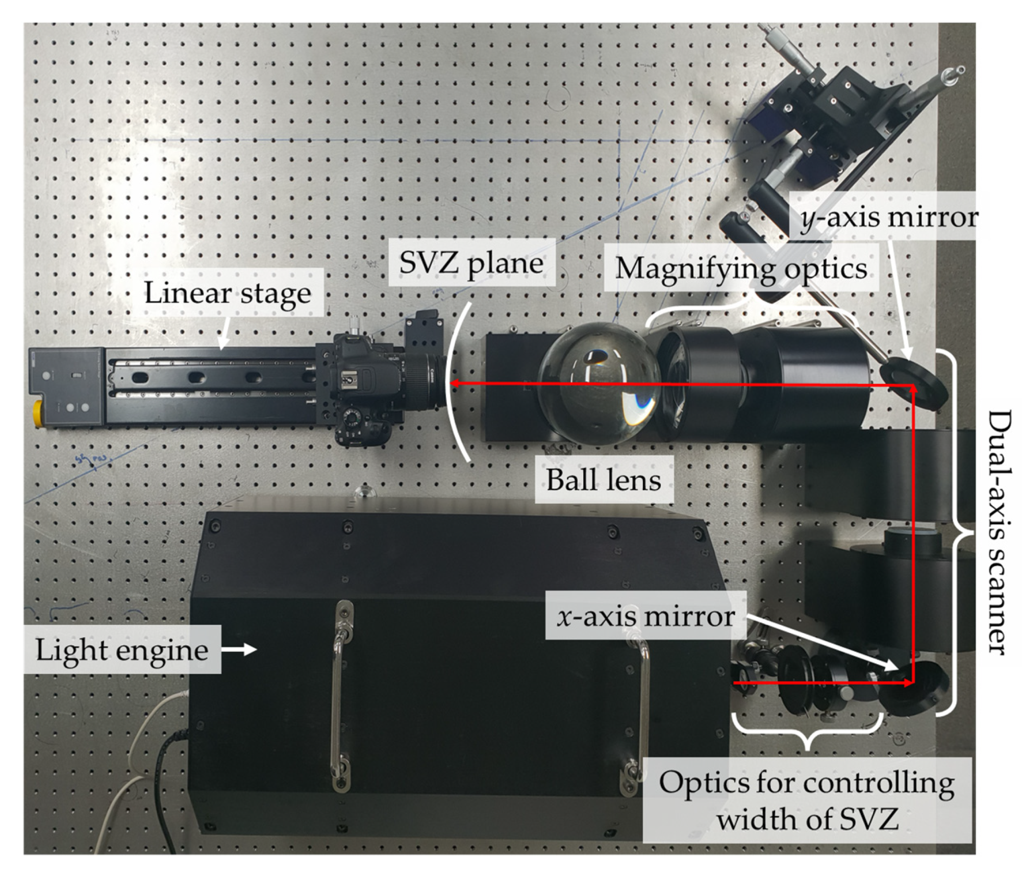
In the full-parallax multiview system, the observation is examined experimentally and the feasibility of the WDF analysis is verified. The views are synthesized experimentally at three different positions. At the SVZ, only a single view is observed, as expected. At the IVZ, the integrated view is observed, which comprises vignetted views. Outside of the VZ, the captured image is vignetted, despite synthesizing all views. Figure 6 shows the experimental setup for observation analysis. The setup comprises a light engine, which has three DMDs for full-color content. After passing through the optics for controlling the width of SVZ, the image passed through a dual-axis scanner. In this experiment, we examined the vignetting of views individually and the integration with other views. The rotation stages are used to rotate scanning mirrors manually and every image is captured at a fixed scanning angle. We generated 9 by 9 SVZs—nine horizontal and nine vertical SVZs. The width of each SVZ was 2 mm, and a scanning angle step-size of 0.85° was used in the experiment.
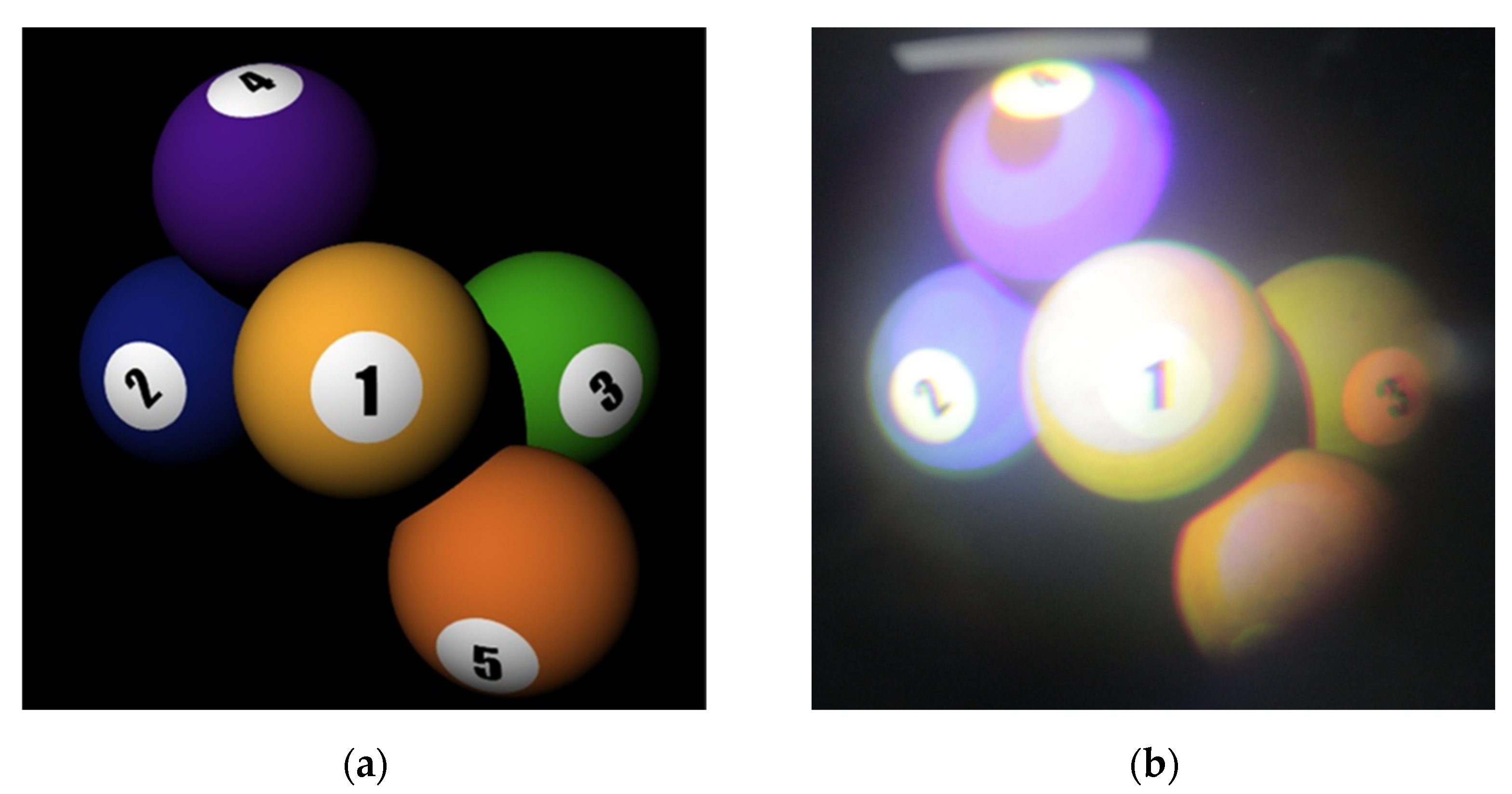
Figure 7 shows the target captured images at the second eye position. Figure 7a shows the target image with five billiard balls located at different depths. As the second eye position is at the reference viewing distance, the captured image is almost identical to the target image, as shown in Figure 7b.
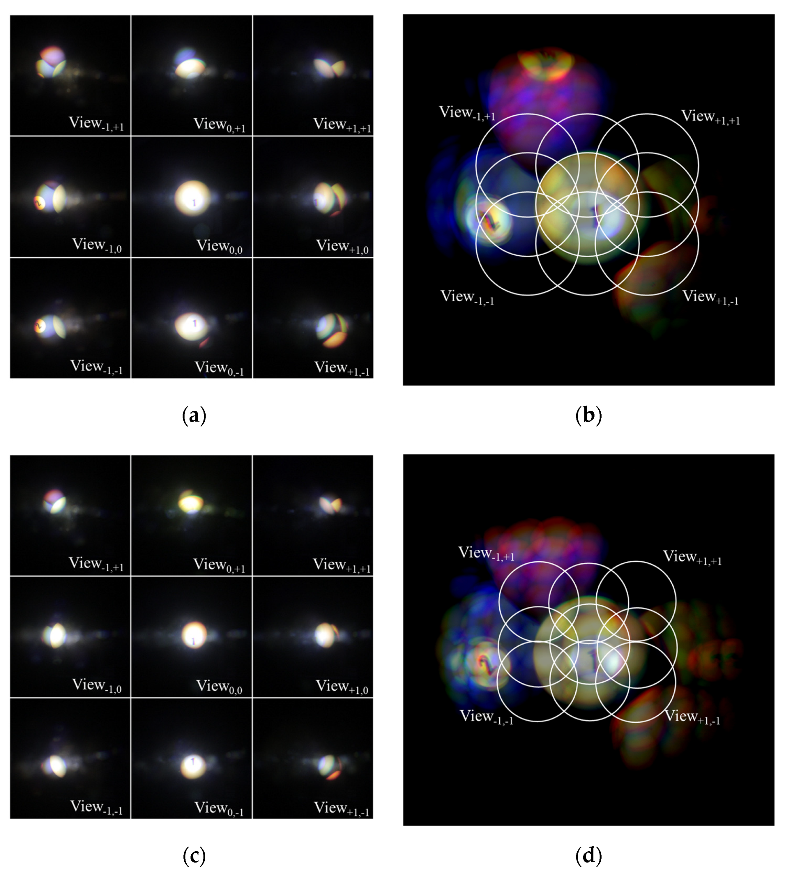
Next, the integration of vignetted views at two different observation positions are experimentally analyzed. For this analysis, 9 by 9 images are captured, and the integrated view is then synthesized via image processing. Observations are made from the fourth and fifth eye positions. In the experiment, the fourth eye position is 375 mm, and the fifth eye position is 525 mm from the center of the ball lens. Figure 8a shows 3 by 3 out of 9 by 9 captured images at the fourth eye position. Each view is vignetted and the positions of the circle of vignetting are different from each other, as expected. Figure 8b shows the integrated view obtained by integrating all 9 by 9 vignetted views. Here, the white ring indicates the circle of vignetting for an individual view. The positions of the rings are equally spaced according to the order of the view. The overlaps between adjacent rings also appear in the integrated view. Figure 8c shows 3 by 3 out of 9 by 9 captured views at the fifth eye position. These results appear identical to those in Figure 8a because each view is vignetted in a circular shape. However, there is a significant difference because the size of the circle is relatively small, and the shift of the circle is less. This difference is apparent when the integrated view in Figure 8d is compared with that in Figure 8b. Notably, the integrated view in Figure 8d is vignetted despite the synthesis of all 9 by 9 captured views. Specifically, the visible area in the integrated view decreases as the eye position at the maximum viewing distance increases.
The results of this experiment can be conveniently interpreted using WDF analysis. Figure 9 presents the WDFs of the views at the fourth and fifth eye positions. As mentioned previously, the circles of vignetting overlap each other at the fourth eye position. Each view is vignetted by the WDF of the observation, as shown in Figure 9a. Here, each view is slanted such that it overlaps the adjacent view along the spatial frequency axis. By contrast, the circle of vignetting at the fifth eye position is relatively small. In Figure 9b, each view is more slanted compared to the previous case. Therefore, the interval between the views along the spatial frequency axis is small. Additionally, as is evident from the red dashed lines defining the top and bottom of the WDF of the observation outlined in blue in Figure 9b, there is vacant room at both ends. This explains the vignetting at the edges of the integrated view.
4. High-Speed Wide-Angle Dual-Axis Scanning Optics
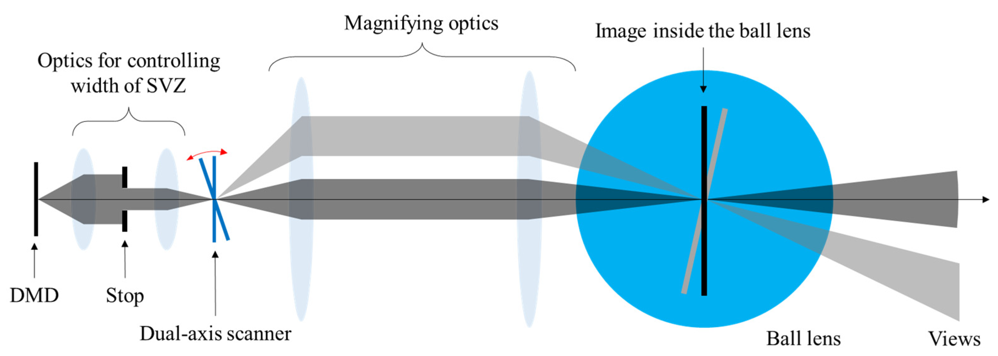
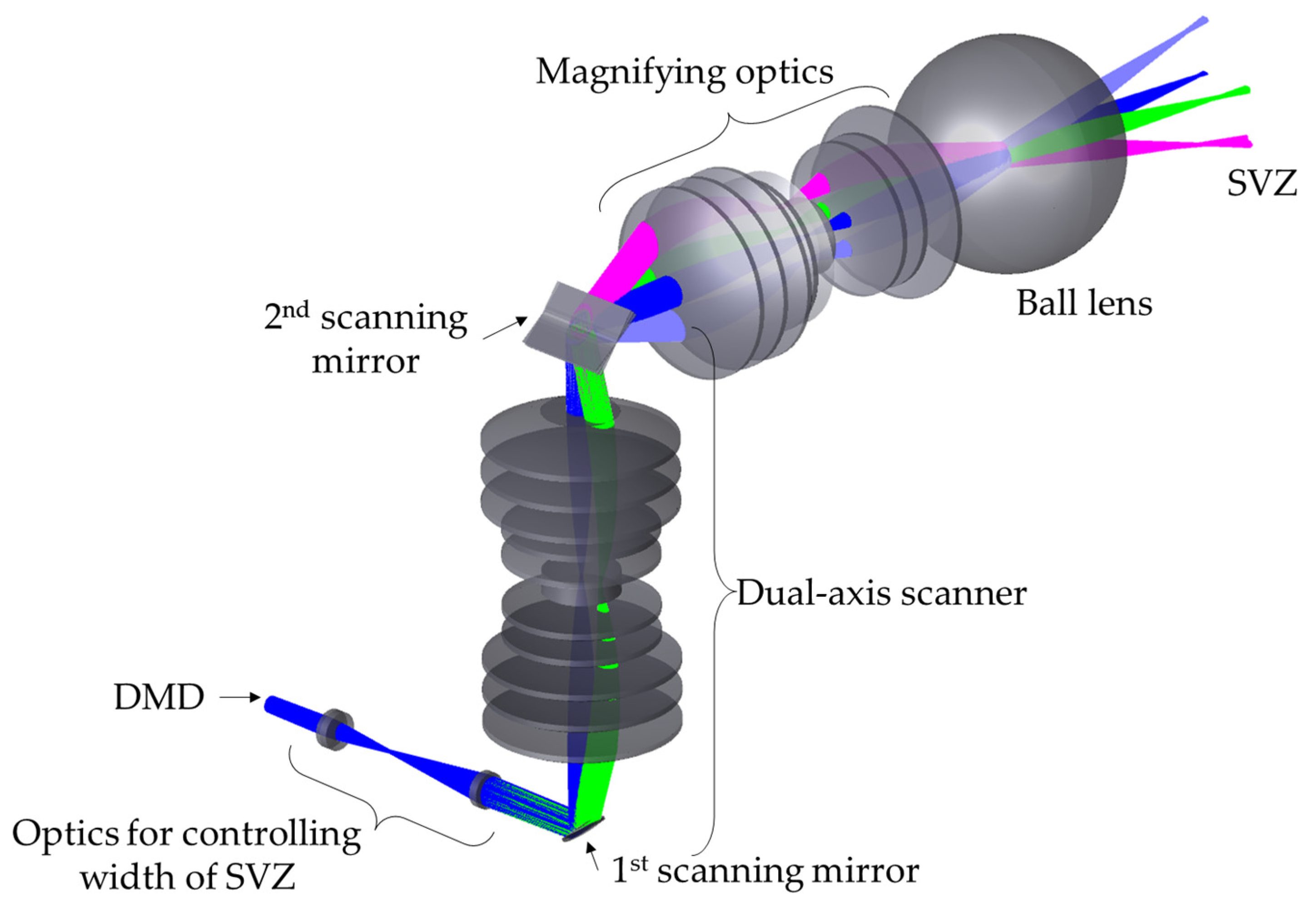
Figure 10 shows the optical structure of the full-parallax multiview display implemented in this study. The view is generated by three DMDs respectively assigned to red, green, and blue (RGB) colors and subsequently passes through 4-f optics with a stop. The optical stop defines the field of view at the individual SVZ, and the size of the stop is directly related to the width of the SVZ. The image is projected onto the first scanning mirror of the dual-axis scanner. This scanner comprises two scanning mirrors along with high-NA scanning optics. Scanning optics play an important role in the effective placement of the two rotational axes of scanners on a common plane. The scanning optics has a basic 4-f structure. The front and rear focal planes have rotational axes for each scanner and are conjugate to each other. After the dual-axis scanner, the image tilted at a predetermined angle is magnified by 4-f optics and appears in the center of the ball lens.
Generally, a full-parallax multiview display using temporal multiplexing requires a high-speed operating spatial light modulator (SLM) and a dual-axis optical scanner. A dual-axis scanner is required to determine the characteristics of the system such as viewing angle, view volume, and frame rate. Although two types of dual-axis scanners, micro-electromechanical system (MEMS) and OXCT, are widely used, these have limited applicability in full-parallax multiview displays owing to intrinsic problems. A MEMS scanner typically has only one scanning mirror, which is tilted via micro actuators around two axes. Therefore, the available beam size is small and the scanning angle is insufficient. An OXCT scanner contains two scanning mirrors connected in a cross configuration, and the gap between the two scanning mirrors causes pincushion error. Therefore, a dual-axis optical scanner with a large beam size and a wide scanning angle that is not susceptible to undesirable pincushion error is required.
We used a resonance scanner and a galvanometer to implement the high-speed dual-axis scanner. The resonance scanner exhibits a very high resonant frequency; however, it is difficult to finely adjust the frequency. By contrast, a galvanometer is relatively slow, but it is easy to electrically control the scanning phase. The phase of the galvanometer, that rotates around the x-axis, is tuned to be synchronized with the resonance scanner, which rotates the view around the y-axis. Arranging the scanners in this manner enabled the implementation of a raster scan. To avoid pincushion errors, the two rotation axes must be placed on a common plane, and the 4-f structure is preferable. This is because if two scanners are connected with an imaging lens, the beam reflected from the second scanning mirror diverges due to the diverging spherical phase, and the aperture of the optics following it will have to be increased.
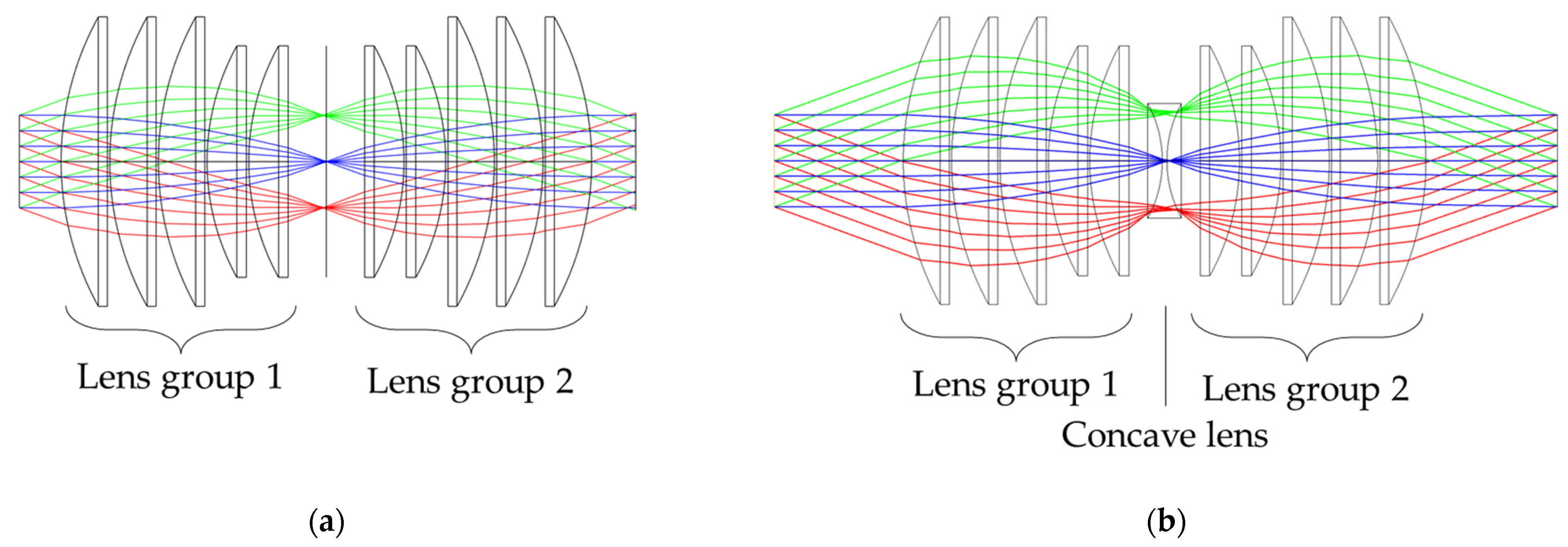
We designed wide-angle scanning optics using commercial lenses inspired by a hypergon lens, which is symmetrical with respect to an optical stop and has the advantages of wide angles and low distortion. We used the optical design software, optics studio (Zemax), to design optical structure for scanning optics. Figure 11 shows two high-NA scanning optics based on the 4-f structure. Figure 11a shows scanning optics with two lens groups symmetrical to each other. These optics have a sufficiently large NA; however, there is insufficient space to place the scanning mirror, which poses a practical challenge. Figure 11b depicts the addition of a concave lens between lens groups 1 and 2 to increase the working distance. This ensures that there is enough space to place the scanning mirror. Additionally, geometric aberration is reduced in the off-axis region after the insertion of the concave lens. The parameters for the scanning optics are listed in Table 1.
5. Experimental Results
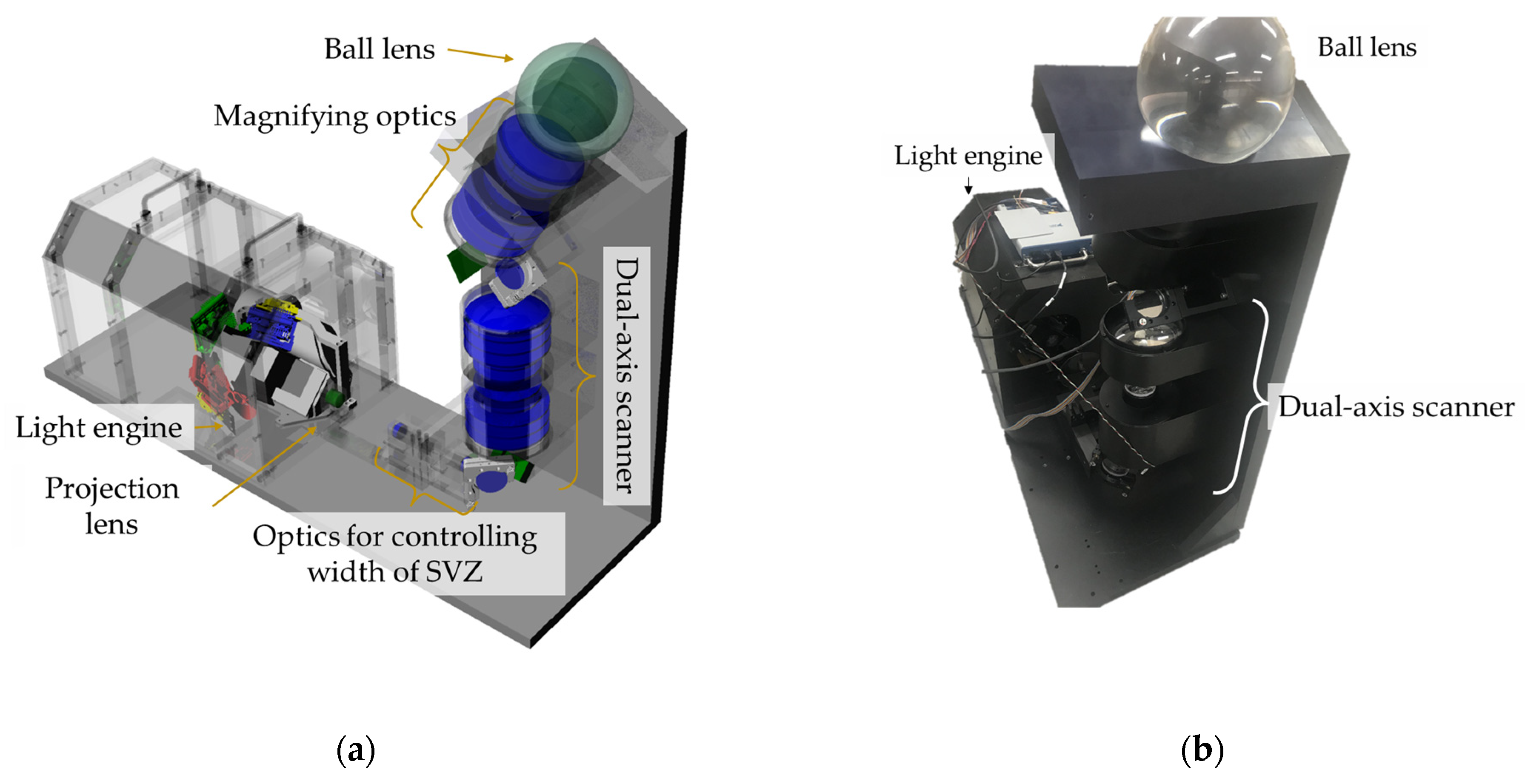
The high-speed wide-angle dual-axis scanner is applied to a full-parallax multiview display with spherical symmetry, as shown in Figure 12. The system structure and the prototype implementation are depicted in Figure 12a,b, respectively. We used the 3D rendering software, Rhino 6 (McNeel), to design optical mounts. The light engine, which consists of three DMDs, each modulating red, green, or blue images, was used for high-speed projection of full-color images [28]. The V-7000 with a resolution of 1024 by 768 pixels (ViALUX) was used, and the number of the active pixels was 768 by 768. The RGB images are combined using a trichroic prism and projected onto the inside of the ball lens through the dual-axis scanner and magnifying optics. The dual-axis scanner comprises two scanners and a high-NA scanning optics. The resonance scanner is driven at 240 Hz with 30-degree scanning angle and rotates an image around the horizontal axis. The galvanometer scanner is driven at 12 Hz with 40-degree scanning angle and rotates an image around the vertical axis. Although the resonance scanner has a high frequency, it is difficult to finely adjust the frequency. Therefore, we used the resonance scanner in conjunction with the galvanometer. The NI-6366, with a maximum sample rate of 2 MS/s and maximum update rate of 3.3 MS/s (National Instruments), was used to synchronize the scanners. The acceptance angle of the dual-axis scanner determined by the scanning optics was 22.1 degrees. The magnifying ratio of the magnifying optics relaying the image from the scanner to the ball lens was 1.33. The ball lens had a diameter of 150 mm. The specifications of each scanner and dual-axis scanner are listed in Table 2.
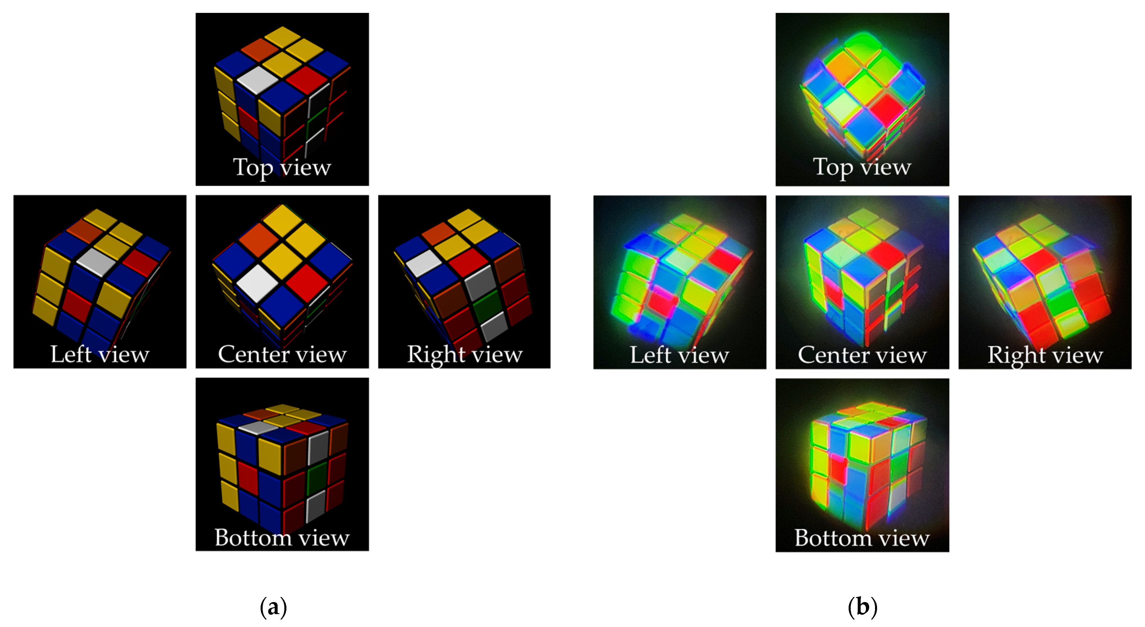
Figure 13 presents the experimental results of the proposed full-parallax multiview images according to the viewing angle. The target object is a puzzle cube, and several view images are rendered at different angles—top, bottom, center, left, and right by 20 degrees, as shown in Figure 13a. Figure 13b shows the views captured by the cameras located at different angles. The camera positions are rotated 20 degrees up, down, left, and right from the center. The captured views are almost identical to the target images, as expected. However, some color dispersion appears in the left, right, top, and bottom views, as is evident from the side views. For example, in the left view, the red color shifts rightward, but in the right view, the red color shifts to leftward. The color dispersion appears because the region colored by the long wavelength shifts into the optical axis. Conversely, the region colored by the short wavelength shifts into the radial direction. The primary reason for the color dispersion is that scanning optics are composed of only off-the-shelf singlet lenses, which are designed at the center wavelength and chromatic aberration is not corrected.
6. Discussion
We proposed the full-parallax multiview display, and our system is a kind of volumetric display because it constructs view volume in the ball lens. So, we selected four remarkable systems for comparison with our proposed system and they are listed in Table 3. Four remarkable systems use multiplexing methods, but multiplexing has a limit to express 3D content with wide viewing angle. System 1 and system 2 are based on the spatial multiplexing method. They require a large number of SLMs. Systems 3 and 4 are based on temporal multiplexing. They require a high-speed driving SLM and scanner, and there is a limit to increasing the number of views with sufficient frame rate and brightness. Systems 1–4 cover the 360-degree horizontal viewing angle, and they need a lot of horizontal views. In other words, they only generate horizontal parallax because of the limitation of their methods, and it appears as distortion according to viewing distance. By contrast, the proposed system allocates horizontal and vertical view for the full-parallax system. It offers better performance than the horizontal parallax-only multiview display because the latter has an intrinsic problem of image distortion in the vertical direction when the viewing distance of the observer changes. To examine this phenomenon, we analyzed the observation characteristics within the VZ using WDF. For the experiment, we changed two scanners to manually controllable mirrors. Moreover we captured the SVZ with 81 SVZs, nine each in horizontal and vertical directions by manually controlling the reflecting angle to analyze IVZ. Finally, we showed the content without distortion in Section 3, unlike horizontal parallax-only systems. The WDF analysis and IVZ experimental results demonstrate the applicability of the full parallax multi-view display.
7. Conclusions
We implemented a full-parallax multiview system with spherical symmetry and fabricated a high-speed wide-angle dual-axis scanner. This scanner comprises two single-axis scanners, a resonance scanner and galvanometer scanner, connected by high-NA scanning optics. Additionally, we designed the scanning optics to reduce the pincushion error due to mismatch of the common plane of each scanner, such that the image plane is eventually located in the ball lens. The proposed system has a field of view of 40 degrees and generates 400 SVZs, 20 horizontally and 20 vertically with 20 fps. Specifically, when the viewing distance increases, distortion, shown in the experimental results herein, appears. Although the horizontal viewing angle of the proposed system is not 360 degrees, it does not show distortion in the specific viewing distance range. In addition, the proposed system has a capability of changing the SVZ width by adjusting the aperture size in the Fourier domain. In a future study, we will perform experiments to analyze human vision perception according to the change in SVZ width and interval between adjacent SVZs in multiview displays. The WDF analysis on VZ and the proposed system can help evaluate the characteristics of multiview systems.
Author Contributions
Conceptualization, D.H. and J.H.; methodology, D.H. and J.H.; software, G.C.; formal analysis, D.H., S.L. and J.H.; validation, D.H. and G.L.; writing—original draft preparation, D.H.; writing—review and editing, D.H., S.L. and J.H.; supervision, J.H.; All authors have read and agreed to the published version of the manuscript.
Funding
This work was funded by Samsung Research Funding and Incubation Center of Samsung Electronics under Project Number SRFC-IT1301052.
Institutional Review Board Statement
Not applicable.
Informed Consent Statement
Not applicable.
Data Availability Statement
Not applicable.
Conflicts of Interest
The authors declare no conflict of interest.
References
- Hong, J.; Kim, Y.; Choi, H.; Hahn, J.; Park, J.; Kim, H.; Min, S.; Chen, N.; Lee, B. Three-dimensional display technologies of recent interest: Principles, status, and issues. Appl. Opt. 2011, 50, H87–H115. [Google Scholar] [CrossRef] [PubMed] [Green Version]
- Geng, J. Three-dimensional display technologies. Adv. Opt. Photonics 2013, 5, 456–535. [Google Scholar] [CrossRef] [PubMed] [Green Version]
- Martínez-Corral, M.; Javidi, B. Fundamentals of 3D imaging and displays: A tutorial on integral imaging, light-field, and plenoptic systems. Adv. Opt. Photonics 2018, 10, 512–566. [Google Scholar] [CrossRef] [Green Version]
- Lueder, E. 3D Displays: Autostereoscopic Displays; John Wiley & Sons, Ltd.: Chichester, UK, 2012; pp. 73–130. [Google Scholar]
- Yoshida, S. fVisiOn: 360-degree viewable glasses-free tabletop 3D display composed of conical screen and modular projector arrays. Opt. Express 2016, 24, 13194–13203. [Google Scholar] [CrossRef] [PubMed]
- Ni, L.; Li, Z.; Li, H.; Liu, X. 360-degree large-scale multiprojection light-field 3D display system. Appl. Opt. 2018, 57, 1817–1823. [Google Scholar] [CrossRef]
- Kawakami, T.; Date, M.; Sasai, M.; Takada, H. 360-degree screen-free floating 3D image in a crystal ball using a spatially imaged iris and rotational multiview DFD technologies. Appl. Opt. 2017, 56, 6156–6167. [Google Scholar] [CrossRef] [PubMed]
- Yendo, T. The Seelinder: Cylindrical viewable from 360 degrees. J. Vis. Commun. Image. 2010, 21, 586–594. [Google Scholar] [CrossRef]
- Xia, X.; Liu, X.; Li, H.; Zheng, Z.; Wang, H.; Peng, Y.; Shen, W.A. 360-degree floating 3D display based on light field regeneration. Opt. Express 2013, 21, 11237–11247. [Google Scholar] [CrossRef]
- Takaki, Y.; Uchida, S. Table screen 360-degree three-dimensional display using a small array of high-speed projectors. Opt. Express 2012, 20, 8848–8861. [Google Scholar] [CrossRef]
- Inoue, T.; Takaki, Y. Table screen 360-degree holographic display using circular viewing-zone scanning. Opt. Express 2015, 23, 6533–6542. [Google Scholar] [CrossRef]
- Kim, J.; Min, S.-W.; Lee, B. Viewing region maximization of an integral floating display through location adjustment of viewing window. Opt. Express 2007, 15, 13023–13034. [Google Scholar] [CrossRef] [PubMed] [Green Version]
- Dodson, N.A. Analysis of the viewing zone of multi-view autostereoscopic displays. In Proceeding of the SPIE Stereoscopic Displays and Virtual Reality Systems IX, San Jose, CA, USA, 19–25 January 2002. [Google Scholar]
- Lee, B.; Hwang, J.; Son, J. Characteristics of composite images in multiview imaging and integral photography. Appl. Opt. 2012, 51, 5236–5243. [Google Scholar] [CrossRef]
- Said, A.; Culbertson, B. Analysis and management of geometric distortions on multiview displays with only horizontal parallax. In Proceedings of the SPIE Stereoscopic Displays and Applications XXIII, Burlingame, CA, USA, 22–26 January 2012. [Google Scholar]
- Halle, M.W.; Benton, S.A.; Klug, M.A.; Underkoffler, J.S. The Ultragram: A generalized holographic stereogram. In Proceedings of the SPIE Practical Holography V, San Jose, CA, USA, 1–7 February 1991. [Google Scholar]
- Pe’er, A.; Wang, D.; Lohmann, A.W.; Friesem, A.A. Wigner formulation of optical processing with light of arbitrary coherence. Appl. Opt. 2001, 40, 249–256. [Google Scholar] [CrossRef] [PubMed]
- Hahn, J.; Kim, Y.; Lee, B. Uniform angular resolution integral imaging display with boundary folding mirrors. Appl. Opt. 2009, 48, 504–511. [Google Scholar] [CrossRef] [PubMed]
- Jang, J.; Hong, J.; Kim, H.; Hahn, J. Light-folded projection three-dimensional display. Appl. Opt. 2013, 52, 2162–2168. [Google Scholar] [CrossRef] [Green Version]
- Jones, A.; Lang, M.; Fyffe, G.; Yu, X.; Busch, J.; McDowall, I.; Bolas, M.; Debevec, P. Achieving eye contact in a one-to-many 3D video teleconferencing system. ACM Trans. Graph. 2009, 6, 1–8. [Google Scholar] [CrossRef]
- Tanjung, R.B.; Xu, X.; Liang, X.; Solanki, S.; Pan, Y.; Farbiz, F.; Xu, B.; Chong, T.C. Digital holographic three-dimensional displays of 50-Mpixel holograms using a two-axis scanning mirror device. Opt. Eng. 2010, 49, 1–9. [Google Scholar] [CrossRef] [Green Version]
- Li, Y. Beam deflection and scanning by two-mirror and two-axis systems of different architectures: A unified approach. Appl. Opt. 2008, 47, 5976–5985. [Google Scholar] [CrossRef]
- Hahn, J.; Kim, H.; Lim, Y.; Park, G.; Lee, B. Wide viewing angle dynamic holographic stereogram with a curved array of spatial light modulators. Opt. Express 2008, 16, 12372–12386. [Google Scholar] [CrossRef]
- Son, J.; Chae, B.; Son, W.; Nam, J.; Lee, B. Comparisons of viewing zone characteristics of multiview and integral photography 3D imaging. IEEE J. Disp. Technol. 2012, 8, 464–471. [Google Scholar] [CrossRef]
- Zhang, Z.; Levoy, M. Wigner distributions and how they relate to the light field. In Proceedings of the IEEE International Conference on Computational Photography, San Francisco, CA, USA, 16–17 April 2009. [Google Scholar]
- Furlan, W.; Martinez-Corral, M.; Javidi, B.; Saavedra, G. Analysis of 3D integral imaging displays using the Wigner distribution. IEEE J. Disp. Technol. 2006, 2, 180–185. [Google Scholar] [CrossRef]
- Stern, A.; Javidi, B. Sampling in the light of Wigner distribution. J. Opt. Soc. Am. A 2004, 21, 360–366. [Google Scholar] [CrossRef] [PubMed]
- Lim, S.; Jeon, H.; Jung, M.; Lee, C.; Moon, W.; Kim, K.; Kim, H.; Hahn, J. Fatigue-free visual perception of high-density super-multiview augmented reality images. Sci. Rep. 2022, 12, 2959. [Google Scholar] [CrossRef] [PubMed]
- Yoshida, S. Virtual multiplication of light sources for a 360°-viewable tabletop 3D display. Opt. Express 2020, 28, 32517–32528. [Google Scholar] [CrossRef]
- Makiguchi, M.; Sakamoto, D.; Takada, H.; Honda, K.; Ono, T. Interactive 360-degree glasses-free tabletop 3D display. In Proceeding of the 32nd UIST, New Orleans, LA, USA, 20–23 October 2019. [Google Scholar]
- Kim, J.; Lim, Y.; Hong, K.; Kim, H.; Kim, H.; Nam, J.; Park, J.; Hahn, J.; Kim, Y. Electronic tabletop holographic display: Design, implementation, and evaluation. Appl. Sci. 2019, 9, 705. [Google Scholar] [CrossRef] [Green Version]
- Park, M.; Ko, M.; Heo, D.; Jeon, H.; Jung, M.; Hahn, J. See-through 360-degree high-speed light-field display using holographic asymmetric diffuser. In Proceedings of the 21st IMID, Seoul, Korea, 25–27 August 2021. [Google Scholar]
Figure 1.
Schematic of the full-parallax multiview display with spherical symmetry.

Figure 2.
Formation of the sub-viewing zone (SVZ) in the proposed system. (a) Viewing distance range and width of the SVZ for the image inside of ball lens, and (b) change in location of the SVZ when the image is rotated around the y-axis.
Figure 2.
Formation of the sub-viewing zone (SVZ) in the proposed system. (a) Viewing distance range and width of the SVZ for the image inside of ball lens, and (b) change in location of the SVZ when the image is rotated around the y-axis.

Figure 3.
Formation of viewing zone (VZ) from SVZs in a multiview display.

Figure 4.
Front and rear integrated view zones (IVZs) for integrated view and SVZs for individual views.
Figure 4.
Front and rear integrated view zones (IVZs) for integrated view and SVZs for individual views.

Figure 5.
Wigner distribution function (WDF) analysis of the proposed system. (a) WDF of each SVZ on the DMD plane; (b) propagated WDF at the viewing distance.
Figure 5.
Wigner distribution function (WDF) analysis of the proposed system. (a) WDF of each SVZ on the DMD plane; (b) propagated WDF at the viewing distance.

Figure 6.
Experimental setup for observation analysis.

Figure 7.
Single view at the second eye position of . (a) Target image; (b) captured image.

Figure 8.
Captured views at two different eye positions. (a) The 3 by 3 of the captured views (9 by 9) at the fourth eye position ; (b) integration from the views in (a); (c) the 3 by 3 of the captured views (9 by 9) at the fifth eye position ; and (d) integration from the views in (c).
Figure 8.
Captured views at two different eye positions. (a) The 3 by 3 of the captured views (9 by 9) at the fourth eye position ; (b) integration from the views in (a); (c) the 3 by 3 of the captured views (9 by 9) at the fifth eye position ; and (d) integration from the views in (c).

Figure 9.
WDFs of the views at the fourth and fifth eye positions. (a) WDF at the fourth eye position; (b) WDF at the fifth eye position.
Figure 9.
WDFs of the views at the fourth and fifth eye positions. (a) WDF at the fourth eye position; (b) WDF at the fifth eye position.

Figure 10.
Optical structure of the proposed full parallax multiview display.

Figure 11.
Comparison of two high-NA scanning optics based on 4-f structure. (a) Conventional configuration with short working distance, and (b) proposed configuration with extended working distance via insertion of a concave lens.
Figure 11.
Comparison of two high-NA scanning optics based on 4-f structure. (a) Conventional configuration with short working distance, and (b) proposed configuration with extended working distance via insertion of a concave lens.

Figure 12.
Proposed full-parallax multiview display with spherical symmetry. (a) Structure and (b) prototype implementation of the proposed system.
Figure 12.
Proposed full-parallax multiview display with spherical symmetry. (a) Structure and (b) prototype implementation of the proposed system.

Figure 13.
Experimental results. (a) Target images and (b) images captured according to viewing angles at −20 degrees left, +20 degrees right, 20 degrees top, and −20 degrees bottom.
Figure 13.
Experimental results. (a) Target images and (b) images captured according to viewing angles at −20 degrees left, +20 degrees right, 20 degrees top, and −20 degrees bottom.


Table 1.
Lens parameters of the proposed scanning optics for the dual-axis scanner.
| Surface | Radius | Thickness | Material | Semi-Dia. |
|---|---|---|---|---|
| Input distance | Infinity | 56 | 25.0 | |
| Convex 1 | −129.2 | 20 | N-BK7 | 62.5 |
| Infinity | 1 | 62.5 | ||
| Convex 1 | −129.2 | 20 | N-BK7 | 62.5 |
| Infinity | 1 | 62.5 | ||
| Convex 1 | −129.2 | 20 | N-BK7 | 62.5 |
| Infinity | 1 | 62.5 | ||
| Convex 2 | −103.5 | 17 | N-BK7 | 50.0 |
| Infinity | 1 | 50.0 | ||
| Convex 2 | −103.5 | 17 | N-BK7 | 50.0 |
| Infinity | 1 | 50.0 | ||
| Concave | 52.2 | 2 | N-BK7 | 25.0 |
| −52.2 | 14.5 | 25.0 | ||
| Convex 2 | Infinity | 17 | N-BK7 | 50.0 |
| 103.5 | 1 | 50.0 | ||
| Convex 2 | Infinity | 17 | N-BK7 | 50.0 |
| 103.5 | 1 | 50.0 | ||
| Convex 1 | Infinity | 20 | N-BK7 | 62.5 |
| 129.2 | 1 | 62.5 | ||
| Convex 1 | Infinity | 20 | N-BK7 | 62.5 |
| 129.2 | 1 | 62.5 | ||
| Convex 1 | Infinity | 20 | N-BK7 | 62.5 |
| 129.2 | 1 | 62.5 | ||
| Output distance | Infinity | 56 | 25.0 |
Table 2.
Specifications of optical scanners in the proposed full-parallax multiview display.
| Parameter | Resonance | Galvanometer | Proposed |
|---|---|---|---|
| Beam size | Ø30 mm | Ø30 mm | |
| Maximum frequency | 240 Hz | 12 Hz | 24 frames/s (20 horizontal lines) |
| Maximum optical scanning angle |
Table 3.
Comparison of the proposed system specifications with other multiview displays using temporal multiplexing and spatial multiplexing.
Table 3.
Comparison of the proposed system specifications with other multiview displays using temporal multiplexing and spatial multiplexing.
| Parameter | System 1 [29] | System 2 [30] | System 3 [31] | System 4 [32] | Proposed System |
|---|---|---|---|---|---|
| System type | Tabletop | Tabletop | Cylinder | Tabletop | Sphere |
| Multiplexing | Spatial | Spatial | Temporal | Temporal | Temporal |
| Parallax | Horizontal | Horizontal | Horizontal | Horizontal | Full |
| Horizontal viewing angle | |||||
| Vertical viewing angle | |||||
| Number of horizontal views | 60 | 288 | 512 | 1,024 | 20 |
| Number of vertical views | 1 | 1 | 1 | 1 | 20 |
Publisher’s Note: MDPI stays neutral with regard to jurisdictional claims in published maps and institutional affiliations. |
© 2022 by the authors. Licensee MDPI, Basel, Switzerland. This article is an open access article distributed under the terms and conditions of the Creative Commons Attribution (CC BY) license (https://creativecommons.org/licenses/by/4.0/).
Share and Cite
MDPI and ACS Style
Heo, D.; Lim, S.; Lee, G.; Choi, G.; Hahn, J. Full-Parallax Multiview Generation with High-Speed Wide-Angle Dual-Axis Scanning Optics. Appl. Sci. 2022, 12, 4615. https://0-doi-org.brum.beds.ac.uk/10.3390/app12094615
AMA Style
Heo D, Lim S, Lee G, Choi G, Hahn J. Full-Parallax Multiview Generation with High-Speed Wide-Angle Dual-Axis Scanning Optics. Applied Sciences. 2022; 12(9):4615. https://0-doi-org.brum.beds.ac.uk/10.3390/app12094615
Chicago/Turabian StyleHeo, Daerak, Sungjin Lim, Gunhee Lee, Geunseop Choi, and Joonku Hahn. 2022. "Full-Parallax Multiview Generation with High-Speed Wide-Angle Dual-Axis Scanning Optics" Applied Sciences 12, no. 9: 4615. https://0-doi-org.brum.beds.ac.uk/10.3390/app12094615
Note that from the first issue of 2016, this journal uses article numbers instead of page numbers. See further details here.