Article

Algorithm of Berthing and Maneuvering for Catamaran Unmanned Surface Vehicle Based on Ship Maneuverability

1
College of Ocean Science and Engineering, Shanghai Maritime University, Shanghai 201306, China
2
Bureau Veritas, Shanghai 200031, China
*
Author to whom correspondence should be addressed.
J. Mar. Sci. Eng. 2021, 9(3), 289; https://0-doi-org.brum.beds.ac.uk/10.3390/jmse9030289
Submission received: 16 February 2021 / Revised: 27 February 2021 / Accepted: 27 February 2021 / Published: 6 March 2021
(This article belongs to the Section Ocean Engineering)

Abstract

:
In the complex port environment, ship berthing manipulation is one of the most difficult operations. In this study, an algorithm of berthing and maneuvering was designed for a catamaran unmanned surface vehicle (USV), which is used for port patrol and protection. Considering the influence of wind, waves, and currents, the mathematical model of the maneuvering movement for the twin-hull and twin-propeller USV was established. Based on the Visual Studio development platform, the USV’s berthing manipulation simulation software was designed. Through the turning simulation experiment of the catamaran USV under different differential rotation speeds of the twin propellers, the relationship between the ship’s turning radius and the propeller speed difference was obtained. A simulation experiment of decelerating and stopping ships at different speeds was carried out, which can provide a reference for speed control when berthing. A berthing maneuvering algorithm based on ship maneuverability was proposed. USV’s berthing algorithm includes three stages: approach process, turning process, and berthing process. In the approach process, the appropriate approach speed was select according to the rotation angle. In the turning process, the right and left propeller speed differences were select. In the berthing process, the berthing speed was controlled according to the berthing distance. In the port environment, a berthing simulation experiment for catamaran USV was carried out. The simulation results show that based on the berthing and maneuvering algorithm, the efficiency and safety of catamaran USV berthing can be improved.

1. Introduction

With the development of intelligent technology, unmanned systems are more and more widely used in various fields. USV has become an important tool for performing specific tasks, such as ocean monitoring, intelligence collection, and transportation. The future development of the oceans urgently needs a large number of USV to support [1]. As a small surface platform with autonomous planning and autonomous navigation capabilities [2], USV can be used in extreme conditions or where personnel are difficult to conduct; this has higher requirements for its own flexibility, as well as the forecast of movement trends in the complex ocean environment. The berthing manipulation is one of the key technologies to realize the USV’s autonomous mission. Therefore, in order to ensure the smooth execution of the USV mission, it is necessary to conduct a simulation study on the USV’s berthing manipulation under the influence of the port environment.
As early as 1900, scientists had proposed the idea of a small water-plane-area twin-hull (SWATH).Until the 1970s, Lang presented with the existing SWATH very similar design—twin pillars sheet design [3]. Then, the achievements made by the Japanese Mitsui Shipbuilding Corporation Research Institute have been particularly eye-catching. Its research and development work can be divided into the following four stages: basic research stage, feasibility research stage, intermediate test boat development stage, and actual ship development stage [4]. At this time, the catamaran USV was used in a series of hydrological surveys, water monitoring, route tracking, relay communication, and other research work [5]. For the twin-hull USV, Tang Yang [6] selected the USV’s speed, maneuverability, seakeeping, and solar system objective functions and independently wrote a set of optimization design software, carried out comprehensive optimization calculations and, finally, obtained optimal ship type parameters of the small waterplane area catamaran. By 2020, Tang Le [7] searched for energy-saving and the efficient dimension of SWATH. Li Guang [8] conducted research on the horizontal directivity of SWATH and the vertical directivity along the length of the ship, proposed SWATH radiation noise generated sound field directivity. The interference effect between catamaran hulls has been considered as an adverse fluid-solid interaction [9]. Chen Deng [10] used a certain L-shaped sheet-hull SWATH and combined the actual ship test results to give the maneuverability results of the ship. A catamaran high-speed passenger ship was chosen for mooring research considering the seakeeping of the ship [11]. The berthing control of USVs has always been one of the hot issues that researchers are committed to studying.
There are wind, wave, and current [12] in the port environment. So, the USV motion mathematical model became complicated and uncertain, which will cause problems such as increased difficulty in berthing and control of the USV and reduced control accuracy. Lee [13] solved the problems of navigation accuracy and ship position measurement through fuzzy control, Line of Sight algorithm, the image object cross-view technology, and other methods in 2010 and realized the thruster assisted berthing. Bai Jun [14] established a mathematical model of the movement of large ships in the harbor and, under the action of preset wind and current, respectively, carried out simulation calculations on the maneuvering of large ships in the process of arriving, turning, and berthing. In 2012, Li Zaobang [15] conducted a simulation study on the remaining speed control, U-turn, and translational arrival process of a fully-loaded Very Large Crude Carrier under shallow water and different wind and current conditions. Li Riling [16] studied the course and speed control of ships, to explore its autonomous berthing method. Okazaki [17] researched and developed a ship handling simulator that uses a mobile Personal Computer to simulate berthing ships and proposed a new method of estimating the parameters of the motion model based on the basic information of the ship. In 2015, Lan Peng [18] established a berthing model of large twin-propeller twin-rudder ships in the harbor under the wind, current, and other loads. Based on the simulation calculation of its berthing operation, the horizontal berthing scheme under different wind and current effects is studied, and the specific berthing scheme is given. Mizuno [19,20] used artificial neural networks (ANN), predictive control, and other methods in 2007 and 2015 to study the precise tracking of ships and berthing paths under uncertain ship interference and achieved certain results. In 2016, the construction of the largest catamaran “Rayleigh 10” was successfully completed. The ship uses an electric propulsion system, and its underwater detection and intelligence capabilities are very prominent [21]. In 2017, Yang [22] introduced an automatic berthing system with a mooring line, which was designed to berth by using a mooring device on the upper deck of the ship. Ablyakimov [23] discussed the development principle and method of a local navigation system based on homodyne signal transformation. This method can establish an effective local navigation system that can be used for the automatic berthing of ships. In 2018, Zeng Xiaolong et al. [24] proposed an autonomous collision avoidance algorithm based on improved bacterial foraging optimization (BFO) for the autonomous collision avoidance planning problem of USV. Im and Nguyen [25] proposed a new artificial neural network controller using a head-up coordinate system containing the relative position of the ship and the distance from the berth. Hu Jingfeng [26] studied the unsteady force characteristics of the rear propeller of the small waterplane area catamaran and compared the accuracy of the numerical calculation method with the experimental results. Taimuri et al. [27,28] present a 6-DoF kinematic model to quickly estimate the maneuvering trajectory and hydrodynamic actions in deep and shallow waters. It can be used for the prediction of maneuvering trajectories of existing or new-build vessels and for estimating the evasive velocity. In 2019, Li et al. [29] proposed a layered artificial potential field trajectory planning method based on multi-constraint analysis of berths, environmental obstacles, and hull dynamics to realize the autonomous trajectory planning of USV. Liu Cunjie [30] pointed out that the SWATH has a small waterplane area. Compared with a monohull with a considerable displacement, it has a weaker resistance to heave and pitch. Inchul Kim [31], based on the experimental results, proposes revising the descriptions of the standard recovery maneuvers and International Maritime Organization regulations on ship maneuverability. The main difficulties of USV in the process of berthing in the port include two aspects—direction control and heading maintenance. Due to the greater influence of wind, waves, and currents under low-speed navigation, considering the space constraints of USV and economic requirements, the hull is usually not equipped with a lateral thruster, which makes it more difficult to control and maintain its heading. Therefore, this article analyzes the maneuverability of the catamaran USV and controls the movement state during the berthing process of the port. The movement state here includes movement such as sailing speed, heading and distance, and geometric parameters. Reasonable selection of these parameters is helpful to the safety of berthing operations.
To sum up, most of the existing research focuses on the berthing of USVs and does not consider the ship type of catamaran USV, which can be based on the application of the propeller speed difference and turning diameter in the berthing process. Considering the influence of various factors on the USV when navigating at low speed in port waters, a relatively complete mathematical model of USV maneuvering movement was established, then the simulation software was designed, which provides a platform for simulating the berthing operation for the USV. A series of berthing maneuvering simulation experiments were carried out, and the changes in motion parameters during the entire berthing maneuvering process were given, so as to provide reliable scientific guidance for the actual berthing process.

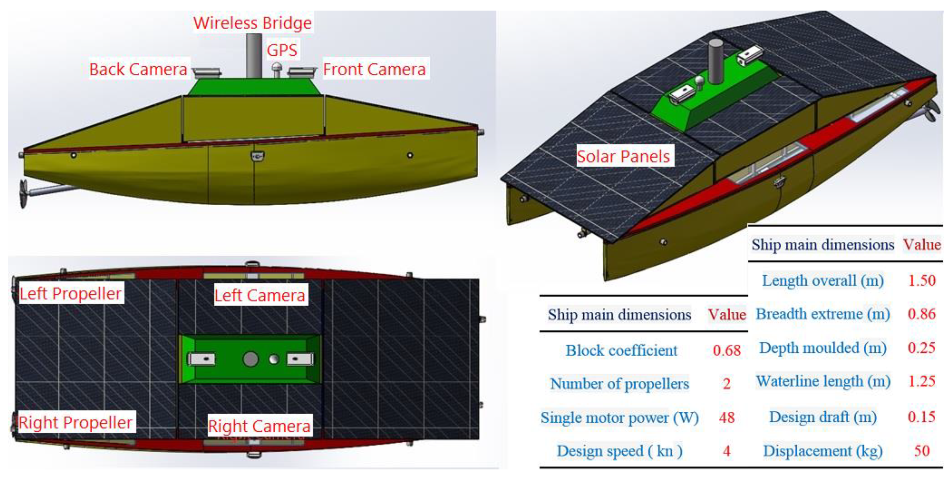
2. Overview of the Catamaran USV

As a new type of marine robot, the catamaran USV has many performance advantages. For the convenience of research, we compare it with a conventional monohull USV to better understand its performance characteristics [5]: (1) Good seakeeping. This is the most outstanding performance of the catamaran USV. Due to the complex and changeable marine environment, the USV often needs to sail against the wind and waves when performing tasks, and when navigating in the waves of the catamaran with the same displacement. The rocking motion of the boat is much smaller than that of a monohull boat, so it is not easy to stall. (2) Good hydrostatic resistance performance. Compared with the monohull, the displacement of the catamaran is concentrated on the main body deeper from the water surface, which greatly reduces the waterline area and reduces the wave resistance. (3) Excellent stability and rotation performance. The distance between the two propellers of the catamaran USV is relatively long, and there are two narrow and long lamellas, so it has good stability compared with the monohull. (4) Large deck area. Since the USV needs to carry various types of mission loads and sensors to perform tasks, it needs a wider deck to carry equipment, and the catamaran USV satisfies this demand well.
In this study, a new catamaran USV was designed. Two propellers were installed in the double hull: left propeller and right propeller. Wireless Bridge was installed on the top of the USV deck tower for communication between the USV and shore-based monitoring station. The USV deck was covered with solar panels to provide continuous power for the USV. In order to monitor the surrounding waters of the USV, four cameras have been installed. The overview map of the USV is shown in Figure 1. The catamaran USV have the advantages of intelligent navigation, efficient operation, and low overall cost. They can be used for port information collection, monitoring, search and rescue, and navigation.

3. Maneuvering Motion Modeling of Catamaran USV

For the convenience of research, assuming constant seawater density, atmospheric density, and gravitational acceleration, the sea surface is regarded as a plane; ignoring the curvature of the earth, the ground coordinate system is regarded as an inertial coordinate system, and the two hulls of the catamaran are symmetrical about the central axis. Additionally, ignore the hydrodynamic interference between the two hulls.

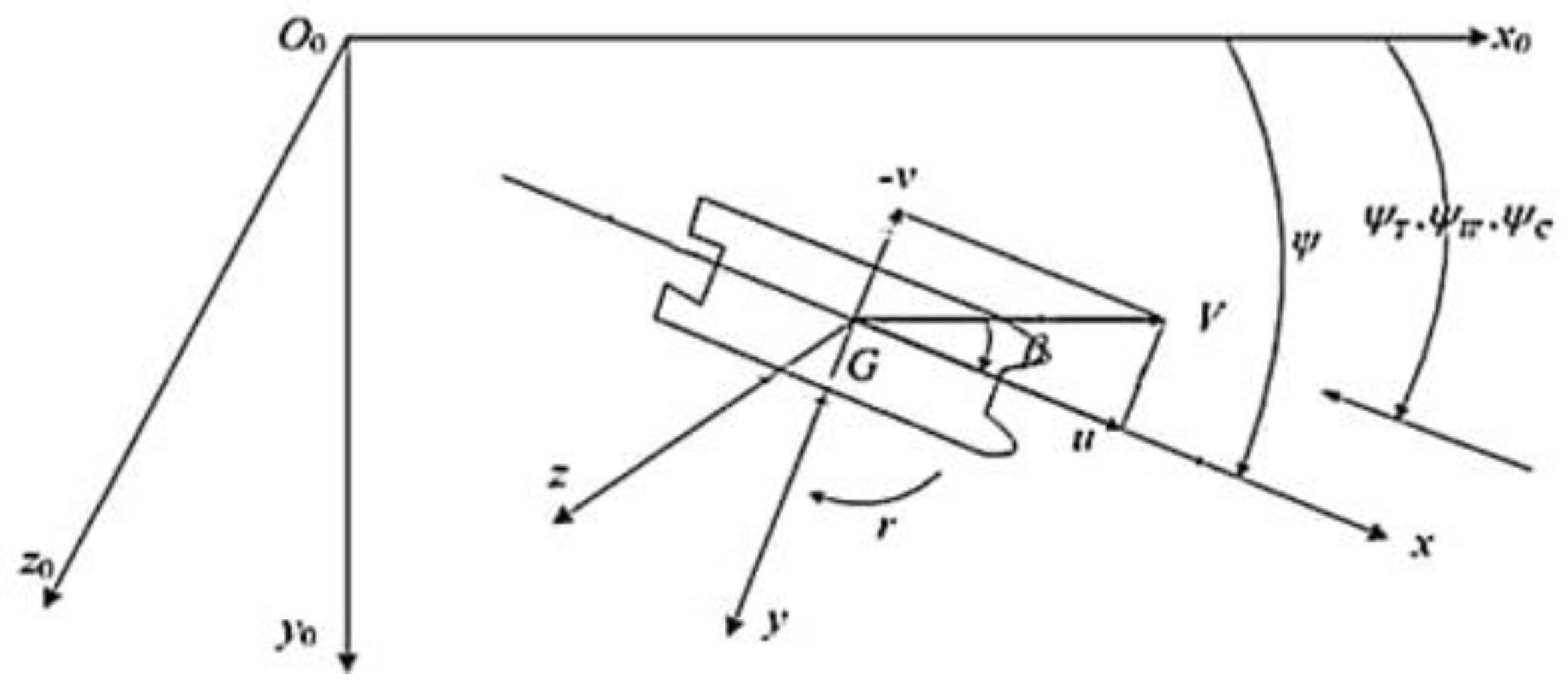
3.1. Coordinate System Establishment and Conversion

(1) Fixed Coordinate System O 0 x 0 y 0 z 0
The fixed coordinate system (referred to as “fixed system”) is fixed on the surface of the earth at a certain moment (t = 0), Somewhere at sea level is used as the origin of the fixed coordinate system. The O 0 z 0 axis is the same as the gravity direction, and its positive direction is vertically downward; the O 0 x 0 axis points to the true north direction, and the O 0 y 0 axis points to the true east. The directions of wind, waves, and currents are represented by ψ C , ψ T , ψ W in the Figure 2.
(2) Coordinate System G x y z
The onboard moving coordinate system G x y z (referred to as the “dynamic system”) moves with the USV. Its origin is taken at the center of gravity G. G x , G y , G z are the intersection lines of the waterline plane, the horizontal middle section and the vertical middle section passing through the center of gravity, respectively. According to the right-hand rule in the positive direction, G x goes to the head, G y goes to the right, and G z goes down. In the motion coordinate system, the maneuvering motion of the USV can be described by the speed u, ν, w and the angular speed p, q, r.
The speed conversion relationship between the fixed coordinate system O 0 x 0 y 0 z 0 and the ship motion coordinate system G x y z .
[ x ˙ y ˙ z ˙ ] = [ cos ψ c o s θ cos ψ sin θ sin ϕ sin ψ cos ϕ cos ψ sin θ cos ϕ sin ψ sin ϕ sin ψ cos θ sin ψ sin θ sin ϕ cos ψ cos ϕ sin ψ sin θ cos ϕ cos ψ sin ϕ sin θ cos θ sin ϕ cos θ cos ϕ ] [ u v w ]
In which, x , y , z are the USV position in the navigation map. ψ , θ , ϕ are the heading angle, pitch, heel of the USV. Conversion relationship of angular acceleration:
[ ϕ ˙ θ ˙ ψ ˙ ] = [ 1 tan θ sin ϕ tan θ cos ϕ 0 cos ϕ sin ϕ 0 sin ϕ / cos θ cos ϕ / cos θ ] [ p q r ]

3.2. The Establishment of a Mathematical Model of Handling the Catamaran USV

According to the theorem of centroid motion and the theorem of moment of momentum:
d B d t = F d K d t = M }
In which, B , K are the momentum of the USV in a fixed coordinate system and the moment of momentum relative to the center of gravity G.
Convert the momentum and moment of momentum in the above formula to the time derivative in the dynamic coordinate system:
d B d t + Ω × B = F d K d t + Ω × K + V × B = M }
where d B d t is the time derivative of momentum B with respect to the dynamic coordinate system; d K d t is the time derivative of momentum K with respect to the dynamic coordinate system.
The maneuvering movement of the catamaran USV on the sea is a complex six-degree-of-freedom movement. Taking into account its good seakeeping performance, in order to facilitate calculation and research, this article assumes that there is no mutual hydrodynamic interference between the two hulls. Additionally, it ignores the heave, pitch, and heel movement during sailing, which is negligible to the algorithm of berthing and maneuvering. Under the influence of environmental factors (wind, waves, currents), the center of the connecting rod between the two boats is selected as the coordinate point, and a three-degree-of-freedom motion equation is established from the above formula:
{ m ( μ ˙ ν r ) = X m ( v ˙ + μ r ) = Y I z z r ˙ = N
in which, m is the mass of USV. The external force and external moment acting on the hull can be expressed as:
{ X = 2 X H + X P l + X P r + X W + X F + X C Y = 2 Y H + Y W + Y F + Y C N = 2 N H + N W + N F + N C

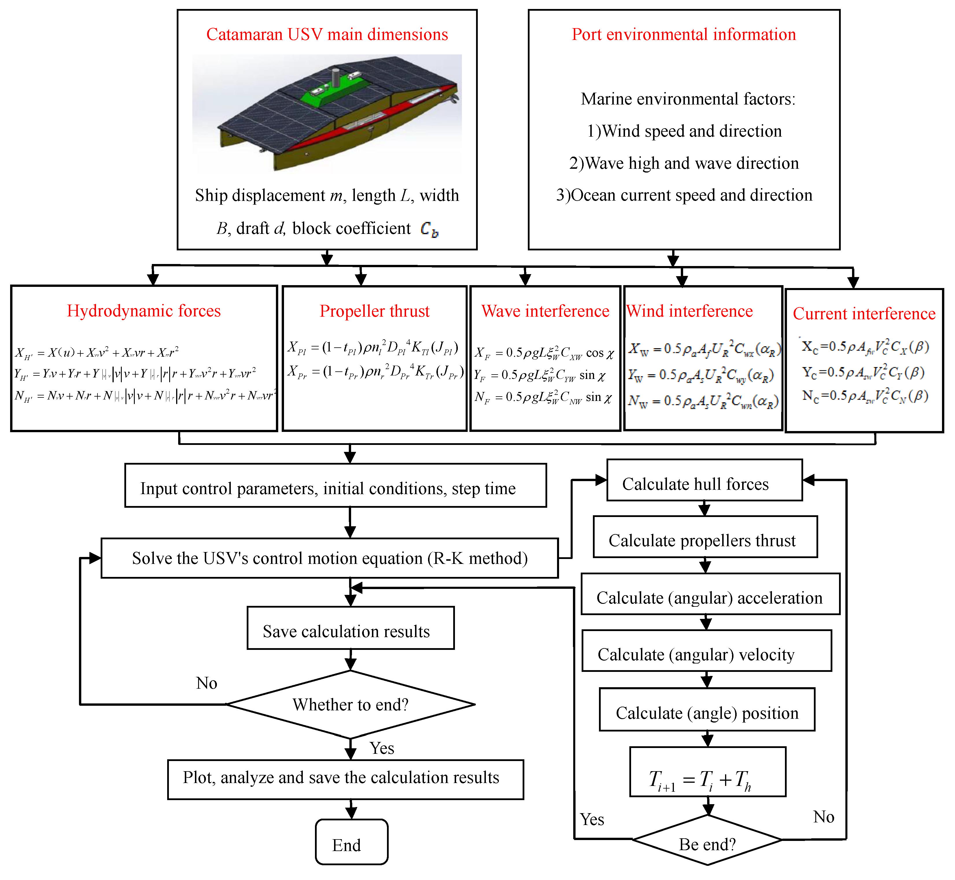
4. Calculation of Forces and Moments

4.1. Calculation of Fluid Dynamics Acting on the Hull

Conventional methods for solving the fluid viscous forces are usually constrained theoretical calculation and experiment but are employed herein Kijima model [32] to calculate the viscosity of the fluid force, which is expressed as follows:
{ X H = X ( u ) + X v v v 2 + X v r v r + X r r r 2 Y H = Y v v + Y r r + Y | v | v | v | v + Y | r | r | r | r + Y v v r v 2 r + Y v r r v r 2 N H = N v v + N r r + N | v | v | v | v + N | r | r | r | r + N v v r v 2 r + N v r r v r 2
in which, X ( u ) = X u u u 2 is the hull resistance during direct sail; X u u , X v v , X v r , X r r are the longitudinal nonlinear hydrodynamic derivatives; Y v , Y r , Y | v | v , Y | r | r , Y v v r , Y v r r are the lateral linear and nonlinear hydrodynamic derivatives; N v , N r , N | v | v , N | r | r , N v v r , N v r r are the linear and nonlinear hydrodynamic derivatives dynamic derivative.

4.2. Propeller Thrust Calculation

In the process of maneuvering movement, the thrust generated by the propeller provides the main control force of the unmanned boat and overcomes the resistance of the water flow. The separated mathematical model proposed by Japanese scholars [33], also known as MMG model, considers the hydrodynamic forces on the ship, rudder, and propeller separately, and the propeller force and torque expressions are established as follows:
In the process of maneuvering motion, the thrust generated by the propeller provides the main control force of the USV and overcomes the resistance of the water flow. The catamaran USV uses the propellers on the left and right hulls to provide thrust. The expressions of the propeller force and torque are established as follows:
{ X P l = ( 1 t P l ) ρ n l 2 D P l 4 K T l ( J P l ) X P r = ( 1 t P r ) ρ n r 2 D P r 4 K T r ( J P r )
in which, t P l , t P r are the thrust derating of the left and right propellers, respectively. Where ρ is the seawater density. n l , n r are the rotation speed of the left and right propellers, respectively. D P l , D P r are the diameter of the two propellers. K T l , K T r are the propeller thrust coefficient function of the two propellers. J P l , J P r represents the propeller advance speed coefficient.

4.3. Wind Interference Force Calculation

During the short period of USV berthing, it can be assumed that the wind encountered is steady. The wind pressure and moment acting on the hull can be expressed by the following Isherwood [34] formula:
{ X W = 0.5 ρ a A f U R 2 C w x ( α R ) Y W = 0.5 ρ a A s U R 2 C w y ( α R ) N W = 0.5 ρ a A s U R 2 C w n ( α R )
in which, ρ a is the air density. Where α R = ψ T ψ is the relative wind direction angle. U R is the relative wind speed; A f is the orthographic projection area of the hull above the waterplane. A s represents the side projection area of the part above the waterline of the hull; C w x ( α R ) , C w y ( α R ) , C w n ( α R ) , respectively, represent the wind pressure coefficient on the axis and the axis direction and the wind pressure moment coefficient around the axis.

4.4. Wave Interference Calculation

The dynamic pressure and moment of the USV in an ideal fluid can be expressed by the following formula [35]:
{ F = S ( t ) Δ p n d s M = S ( t ) Δ p ( r × n ) d s
Among them, S(t) is the submerged surface area of the hull at time t; n is the unit normal vector of the cell surface of the hull; r is the position vector (starting from the moment reference point); Δ p is the dynamic pressure, which can be solved by Bernoulli equation [35].
The second-order wave force is also called the wave drift force. Its processing is more difficult and complicated. Generally, it is calculated by an empirical formula. The calculation formula is as follows:
{ X F = 0.5 ρ g L ξ W 2 C X W cos χ Y F = 0.5 ρ g L ξ W 2 C Y W sin χ N F = 0.5 ρ g L ξ W 2 C N W sin χ
in which, ξ W is the average wave amplitude; C X W , C Y W , C N W is the second-order drift force coefficient of the wave. Where χ = ψ W ψ is the relative wave direction angle.

4.5. Ocean Current Interference Force Calculation

Current force is the force generated by the current on the hull of the boat. During the short period of USV berthing, it is assumed that the ocean current is uniform and constant. The calculation method is as follows:
{ X C = 0.5 ρ A f w V C 2 C X ( φ ) Y C = 0.5 ρ A s w V C 2 C Y ( φ ) N C = 0.5 ρ A s w V C 2 C N ( φ )
in which, V c is the flow velocity. A f w , A s w , respectively, are the underwater orthographic projection area and the lateral projection area of the hull. Where ϕ = ψ C ψ is the relative current direction angle. C X ( φ ) , C Y ( φ ) , C N ( φ ) are test coefficients, which, respectively, represent the force coefficient and the coefficient of upward flow in the direction.

5. Maneuverability Simulation of Catamaran USV

According to the USV maneuvering mathematical model in Section 3, this section will develop a catamaran USV maneuvering simulation software based on the Visual Studio development platform. In the software, using the catamaran USV main dimensions and port environmental information, the hydrodynamic coefficient of the hull, the propeller thrust coefficient, and the interference coefficient of wind, wave, and current will be calculated. Then, various USV manipulation simulation experiments can be performed. The simulation flow chart is shown in Figure 3.
Next, the simulation experiment of USV rotation in still water, the simulation experiment of rotation in wind and waves, and the stopping test of USV will be carried out, respectively. The parameters for simulation such as hydrodynamic coefficients of the USVwere shown in Table 1.

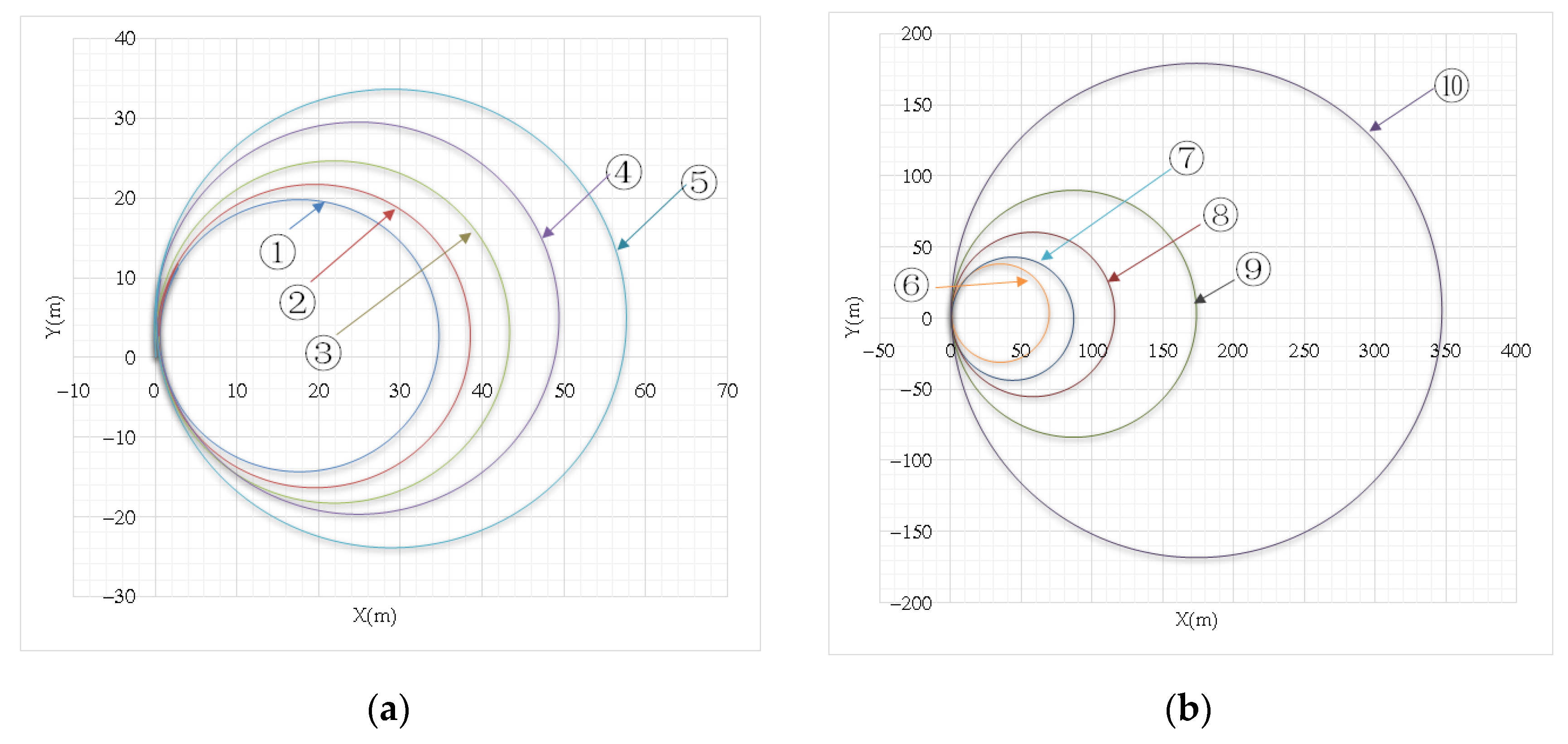
5.1. Simulation Experiment of USV Rotation in Still Water

Under static water conditions, the USV speed before turning is 1 m/s. A number of turn circle simulation experiments with different rotating speed difference (the rotating speed difference between left and right propeller rotating speed) were carried out. The results of turn circle simulation were shown in Figure 4. The numbering ➀~➉ was used to differentiate different turn circle experiments. The maneuverability of the rudderless twin-propeller USV in still water will be discussed next.
Comparing ten different propeller rotating speed difference simulation test data, the specific simulation data areshown in Table 2.
According to the data in Table 2, as the propeller rotating speed difference becomes smaller, the turning angle speed becomes smaller, while the turning time and turning diameter become larger. The relationship between the rotating speed difference and the gyration diameter is shown in the Figure 5.
As shown in Figure 5, when the difference between the left and right propeller rotating speeds increases, the USV turning diameter and turning time decreases. The turning diameter curve was fit using power function fitting method. The fitting formula is y   =   54,983 x 0 . 99 , which will be used in the algorithm of berthing and maneuvering. The independent operation of the left and right propellers gives the USV more flexible maneuverability.

5.2. Simulation Experiment of Rotation in Wind and Waves

A series of turning motion simulations for the catamaran USV with different rotation speed differences were carried out under the influence of wind, waves, and currents. The influence of the steering performance of the USV under the action of wind, waves, and currents was discussed. The initial longitudinal velocity of the USV is 1 m/s, and the USV rotation simulation at different revolutions per minute (RPM) is shown in Figure 6.
The abovementioned series of rotation simulation experiment data were sorted and analyzed. According to the simulated test data of different propeller speed differences in Figure 6, the drift distance of the motion trajectory under the different speed difference of propellers were obtained, and these data are listed in Table 3.
The relationship between the drift distance of the motion trajectory and the rotation speed difference of the propellers under the action of wind, wave, and current is shown in Figure 7.
As shown in Figure 7, when the speed difference between the left and right propellers decreases, the drift distance of the turning trajectory of the catamaran USV will increase, and the increase becomes bigger and bigger. It is shown that the effects of wind, waves, and currents are very significant to the catamaran USV. If the rotation speed difference between the left and right propellers is too small, the USV will be difficult to steer under the action of this wind, waves, and currents. The drift distance curve was fit using power function fitting method. The fitting formula is y   =   58728 x 1 . 5 , which will be used in the algorithm of berthing and maneuvering. Therefore, when manipulating the catamaran USV in the actual marine environment, the speed difference is adjusted in time to ensure its normal steering operation.

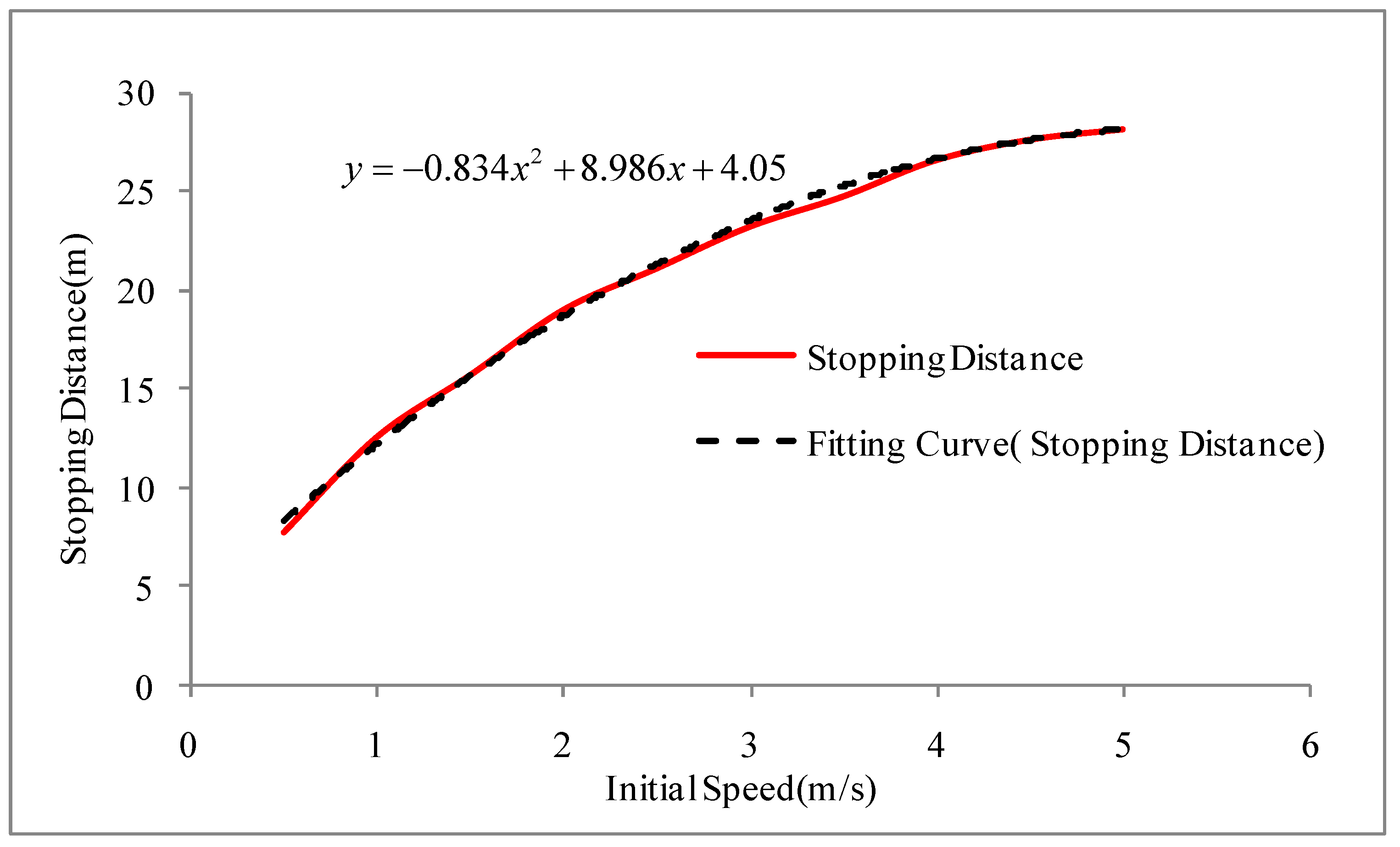
5.3. Simulation of USV Stopping Test

In this part, a series of USV stopping tests have been carried out. The stopping distance has been obtained from the experimental data. The stopping distance is a distance from a position when the main engine stops at a certain speed to a position when the ship stops moving. The stopping distance will be used in the berthing algorithm. Figure 8 shows the results of the simulation experiment of stopping the ship at different speeds in knots (kn).
It can be seen from Figure 9 that the stopping distance varies with the initial speed. When the initial speed is higher, the stopping distance is larger. As shown in Figure 9, the stopping distance at the initial speed of 5 knots is about 3.6 times that of the stopping distance at the initial speed of 0.5 knots. Therefore, the remaining speed control should be paid attention to when entering the berth. The stopping distance curve was fitusing polynomial fitting method. The fitting formula is y = 0.834 x 2 + 8.986 x + 4.05 , which will be used in the algorithm of berthing and maneuvering.

6. Berthing Algorithm and Simulation Verification for Catamaran USV

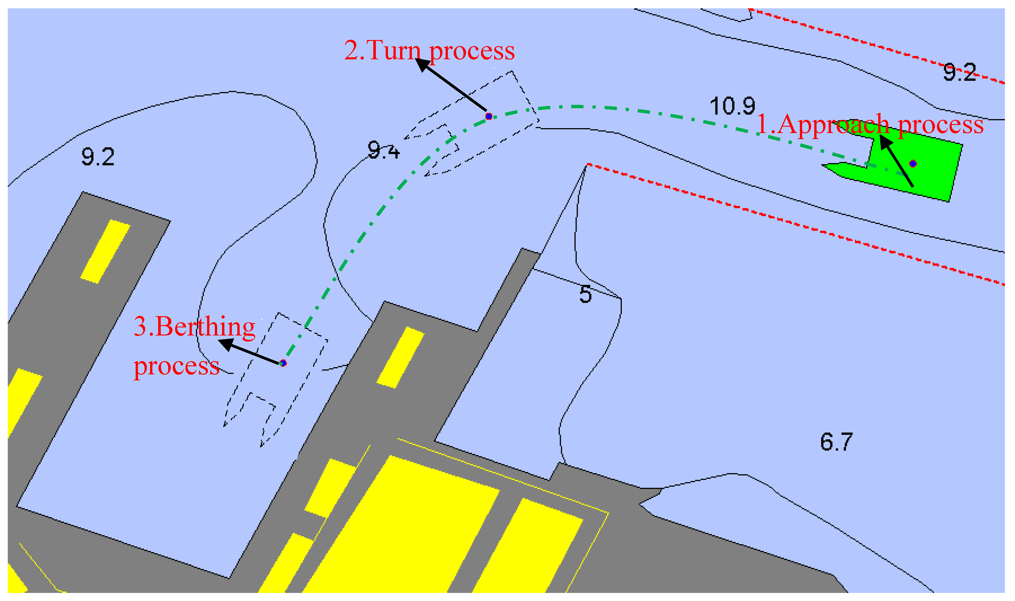
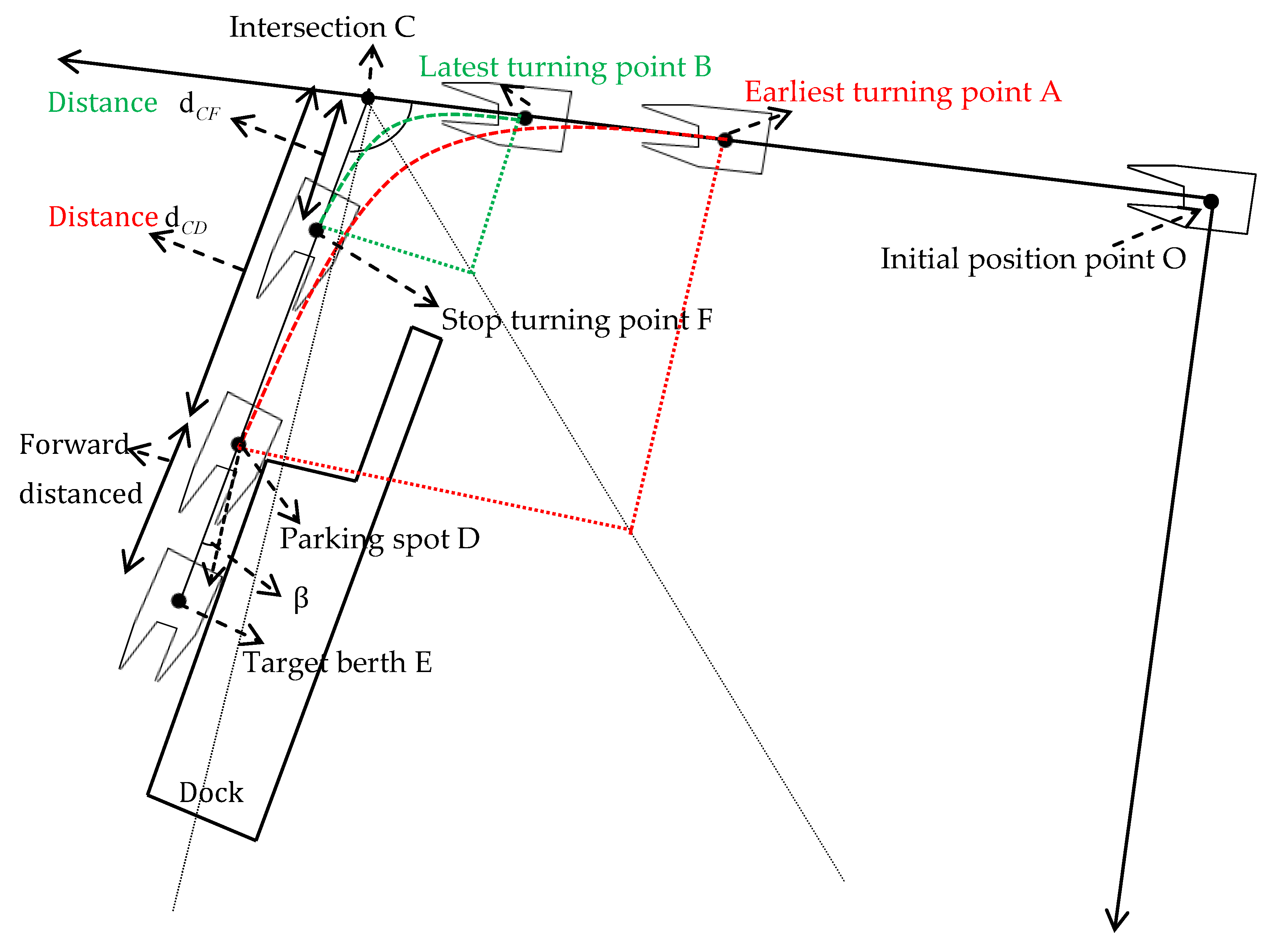
6.1. Berthing Algorithm

Before simulating the berthing and maneuvering process of the catamaran USV through the simulation software, the berthing process must be planned first. The USV’s berthing process was broken down into three steps: approach process, turning process, and berthing process, as shown in Figure 10. Additionally, a new berthing maneuvering algorithm based on ship maneuverability was proposed.
The above berthing plan takes the initial position point O as the origin, and the initial straight track as the x-axis, to establish a plane rectangular coordinate system as shown in Figure 11.
The catamaran USV navigates from the initial position O to a certain position (turning point) and then turns to the left by adjusting the rotation speed difference of the left and right propellers. After passing the turning angle, the USV will reach the direction that can enter the berth smoothly. Finally, it stops propellers at the parking point and uses the remaining speed to slide into the target berth.
The berthing plan here considers two extreme cases: one is that the catamaran USV starts from the initial position, and after going straight to the earliest turning point, it starts to steer by adjusting the speed difference between the left and right propellers, arrives just after turning the head angle, and uses the remaining speed to enter the target berth after the main engine has stopped. The second is that the catamaran USV starts from the initial position and sails straight to the latest turning point, adjusts the left and right propeller speed difference to the maximum within the allowable speed difference range, and performs steering control, stopping turning after passing the turning angle. At this time, the position is set to stop turning point. After continuing to sail to the stopping point, the main engine will stop and use the remaining speed to enter the target berth.
According to the performance simulation data of the catamaran USV in the previous chapter, the rotation speed of the twin propellers required for heading at the turning point is determined by the wind, wave, and current rotation simulation experiment, the relationship between the drift distance and the rotation diameter. Then, the berthing maneuvering process is carried out under the condition that the parameters of the USV, and the wind, wave, and current parameters are determined. Finally, the data of the forward distance and the initial speed in the simulation experiment of the deceleration of the ship are used for the berthing maneuver, and finally, a safe berth is achieved. The berthing planning process was shown in Figure 12. The above process is divided into the following three processes:
(1) Approach Process
The catamaran USV departs from the initial position O ( x 0 , y 0 ) and sails directly to the earliest turning point A ( x A , y A ) or to the latest turning point B ( x B , y B ) .
According to the geometric relationship in the Figure 11, d A C is the distance between the earliest turning point A and the intersection point C, and d B C is the distance between the latest turning point B and the intersection point C. The calculation formulas are shown in Formula (13).
{ d A C = d C D cos β tan α 2 d B C = r max tan α 2 }
Among them, r max represent the radius of gyration at the maximum speed difference, which can be estimated from the fitting curve of the speed difference and the gyration diameter in Figure 6. The earliest turning point A coordinate is:
{ x A = x C d A C y A = 0
The coordinate of the latest turning point B is:
{ x B = x C d B C y B = 0
After determining the coordinates of the earliest and latest turning points, the speed difference between the left and right propellers at the earliest and latest turning points is determined according to the fitting curve of the speed difference and the turning diameter.
(2) Turning Process
The turning process is most crucial. The earliest turning point A and the latest turning point B correspond to the minimum rotational speed difference and the maximum rotational speed difference that can enter the target berth smoothly, that is, at any position between point A and point B, it can enter the target berth with a certain speed difference. It is known that when the USV sails to any position between point A and point B, G ( x G , y G ) starts to adjust the speed difference and starts to steer. Its radius of gyration r G can be obtained by the following formula:
r G = ( x C x G ) tan α 2
At this position point G, the corresponding left and right propeller speed difference can be selected for steering operation according to the size of the radius of gyration r G through the fitting curve of the speed difference and the turning diameter.
Therefore, when turning the head, the corresponding steering distance can be calculated according to the dock position and terrain information. Among the propeller speed differences corresponding to the earliest and latest turning points, a reasonable propeller control differential is selected for berthing control. The schematic diagram of the turning process is shown in Figure 13.
(3) Berthing Process
After completing the turning of the head, it stops turning after the turning angle α . At this time, the position is set to stop turning point F ( x F , y F ) , continues to sail to stop point D ( x D , y D ) ,and then, the main engine will stop and use the remaining speed to enter the target berth point E ( x E , y E ) .
From the geometric relationship in Figure 11: The angle between the forward thrust direction of the USV and the y axis: β = α 90 °
The coordinates of parking point D ( x D , y D ) is:
{ x D = x E d sin β y D = y E d cos β
The forward distance d can be estimated according to the curve of the forward distance and the initial speed in Figure 10, to ensure that the catamaran can enter the target berth point E ( x E , y E ) smoothly after stopping by using the remaining speed.
The distance d C D between point C and point D is:
d C D = ( x D x C ) 2 + ( y D y C ) 2

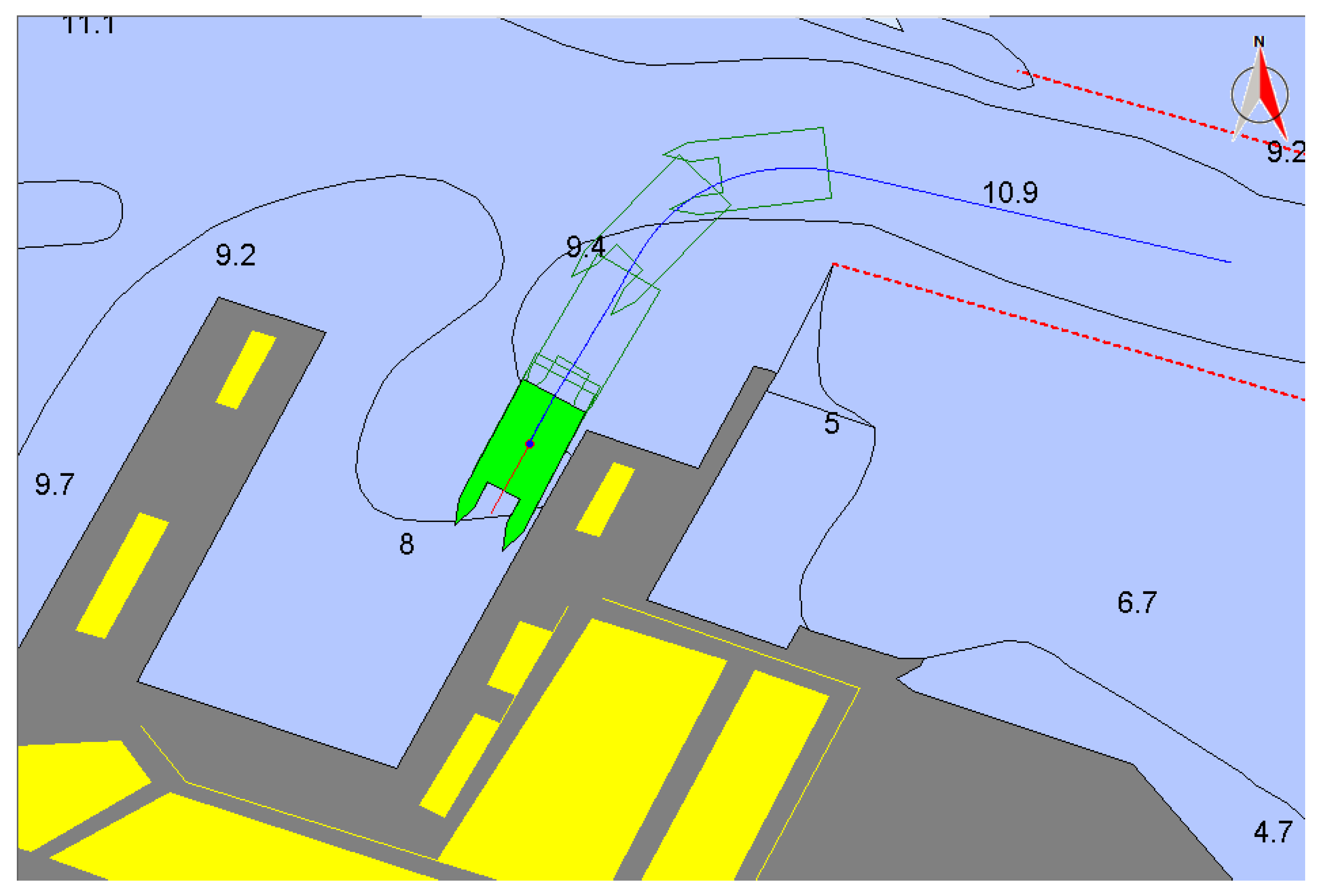
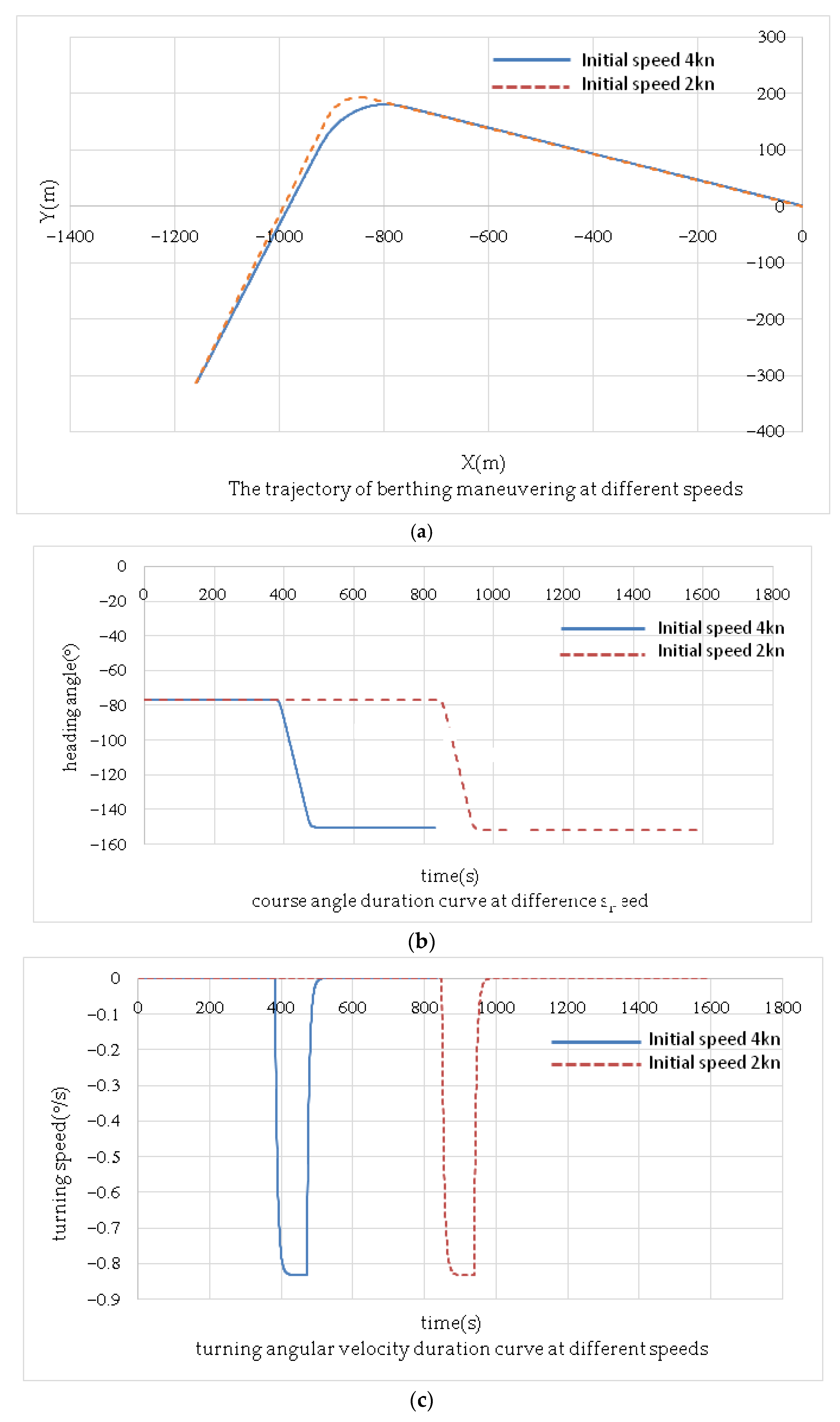
6.2. Berthing Simulation in Calm Water

Under the condition of no wind, waves, and currents, the initial speeds of 4 and 2 kn were simulated. The initial conditions: left propeller speed 800 rpm, right propeller speed 800 rpm, control speed difference 400 rpm, initial heading −77°.
It can be seen from Figure 14 that under the same initial conditions, when the initial speed is 4 kn, the distance difference between the initial position of the turning point at which the unmanned catamaran starts to steer, compared with the distance difference between the turning point position and the initial position when the initial speed is 2 kn, the former is smaller. Additionally, when the speed is small, the required turning water area is larger. Under the same initial conditions, the changes in heading angle and turning angle speed of catamarans with different initial speeds are basically the same during berthing. It shows that when there is no wind, wave, or current, the maneuverability of the catamaran USV is relatively stable when the initial speed is different. Special attention should be paid to the fact that when the initial speed is low, the turning water area required during the steering maneuver is relatively large, and the speed difference between the left and right propellers can be adjusted in advance to ensure smooth parking.

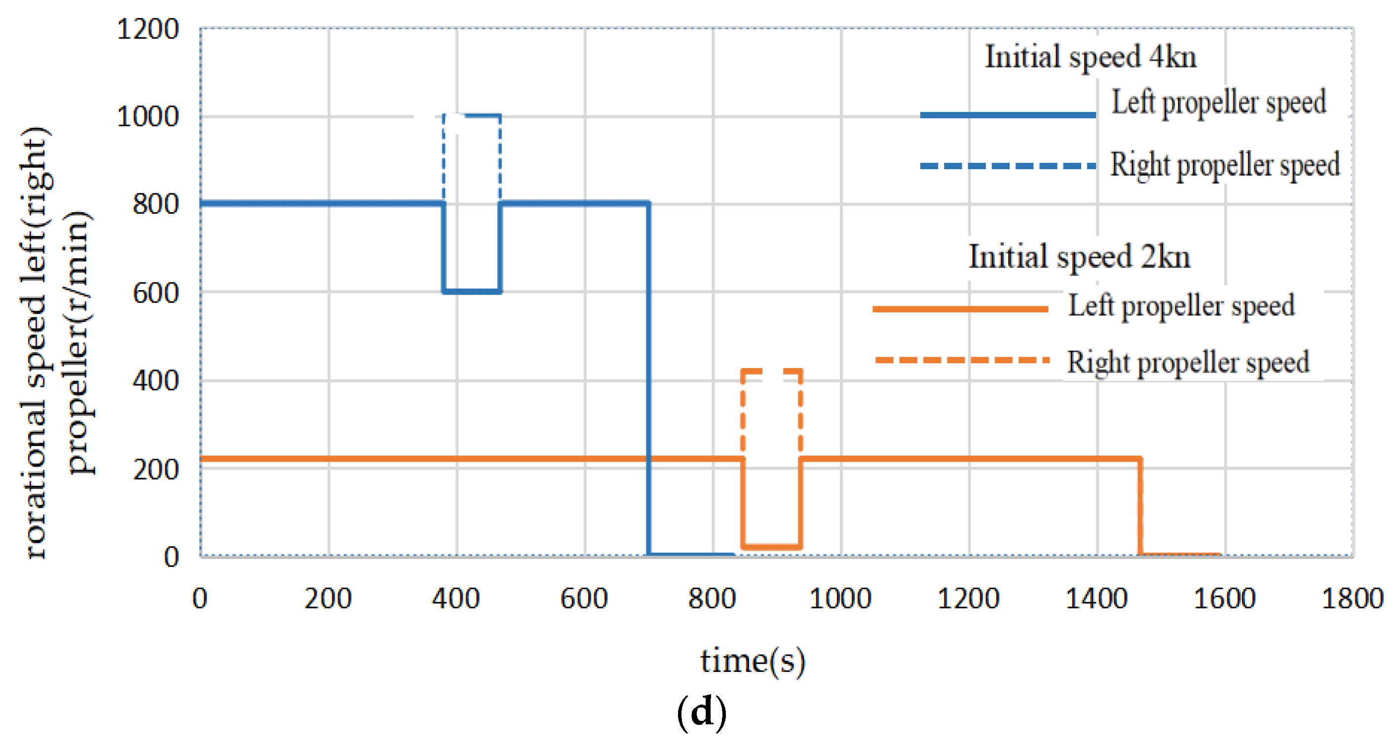
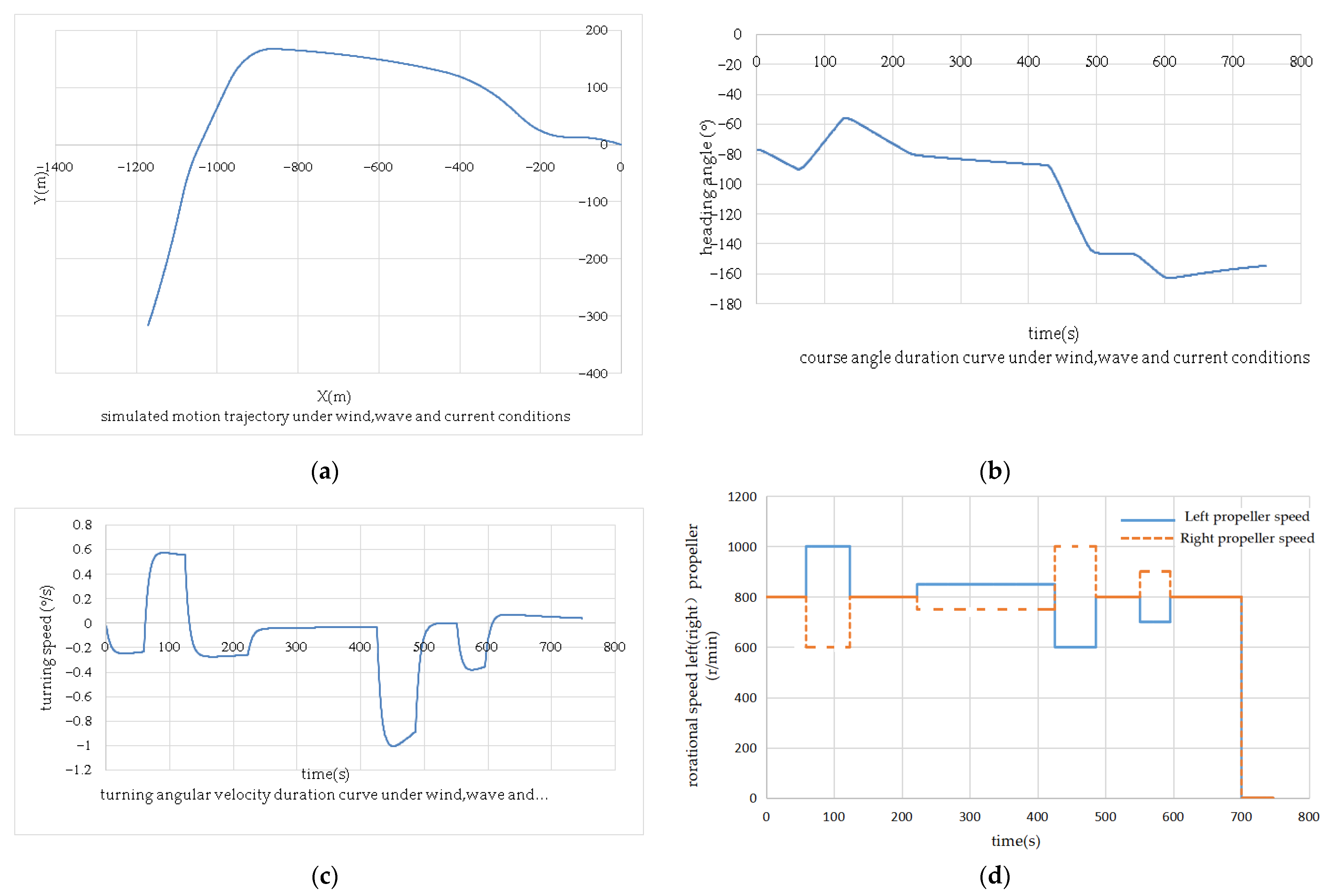
6.3. Berthing Simulation in Wind, Wave, and Current Conditions

In order to verify the established maneuvering motion model of the catamaran USV and to investigate its maneuverability during berthing under the influence of the marine environment, the marine environment at a certain moment in the port of Dalian Port is used as the simulation environment. The whole process of berthing maneuvering motion of the catamaran USV is simulated, and the maneuvering parameters and changes in motion parameters during the whole process are given. Initial conditions: the left propeller rotates at 800 rpm, the right propeller rotates at 800 rpm, the initial speed is 4 kn, and the initial course is −77°. Marine environment parameters: wind speed 6 m/s, wind direction 30°; wave height 0.4 m, wave direction 120°; flow velocity 0.2 m/s, flow direction 45°.
Analyze the simulation test data of the berthing manipulation movement under the action of the wind, waves, and currents, and the results are as follows:
As shown in Figure 15, the simulation results show that when the catamaran USV is berthing at a wind speed of 6 m/s and a wind direction of 30°; a wave height of 0.4 m and a wave direction of 120°; a velocity of 0.2 m/s and a flow direction of 45°, its course is easily shifted from the planned route due to the combined force of wind, wave, and current. Therefore, it is necessary to adjust the control parameters in real time during the berthing process according to the actual movement, to ensure its smooth entry. In order to facilitate the analysis of its berthing and maneuvering conditions under the action of wind, waves, and currents, the trajectory of the unmanned catamaran under the condition of no wind, waves, and currents is compared with the course angle duration curve when the initial speed is the same as 4 kn:
As shown in Figure 16, after the catamaran USV starts to sail from the initial position, it is deflected to the left chord by the combined force of wind, waves, and currents. At this time, it is necessary to increase the rotational speed of the left propeller and reduce the rotational speed of the right propeller to change its heading by generating a torque that is opposite to the combined moment of wind, waves, and currents through the speed difference. However, because it is difficult to accurately grasp the change range of the heading angle, it is necessary to continuously adjust the left and right propellers in real time according to the actual movement during the maneuvering process until the target berth is reached. Compared with the berthing simulation without wind, wave, and current interference, the control of the left and right propellers in the berthing simulation with environmental interference is more difficult, as shown in Figure 16d. In the process of berthing, the difference between the rotational speed of the left and right propellers is needed to resist environmental interference. The turning angular velocity of the USV is affected by the port environment, as shown in Figure 16c, which produces a larger change compared with the simulation of berthing without wind, wave, and current interference. This paper presents the changes in maneuvering control parameters of the catamaran USV during the entire berthing process under the wind, wave, and current conditions as shown in Table 4, which can provide a reference for the actual berthing process.

7. Conclusions

The maneuverability of the catamaran USV was analyzed, and an algorithm of berthing was proposed. The turning simulation test for the catamaran USV under a series of propeller rotation speed differences was carried out. The relationship between the USV turning performance and the propeller rotation speed difference was explored. As the rotation speed difference becomes larger, the turning diameter is continuously reduced, which provides a basis for choosing a reasonable rotation speed difference for the berthing algorithm. Based on the ship stopping test data, when the USV initial speed is higher, its stopping distance is larger. As the initial speed decreases, the stopping distance also decreases. In this way, it provides a reference basis for the residual speed control when entering the berth. A berthing maneuvering algorithm based on ship maneuverability was proposed. USV’s berthing algorithm includes three stages: approach process, turning process, and berthing process. Finally, the berthing simulation for the catamaran USV was carried out under the influence of the wind, wave, and current. Its heading is easily deviated from the planned route due to the marine disturbing force. The berthing algorithm will adjust the maneuvering control force to opposite the disturbing force in real time. Future work will be focused on the study of the automatic berthing for USV in the port environment, which including berthing path planning in an obstacle environment, and berthing control research when there is an obstacle.

Author Contributions

Conceptualization, G.W., Z.H., and Y.C.; methodology, G.W. and Z.H.; software, G.W.; investigation, Y.C.; resources, G.W.; writing—original draft preparation, Z.H. and M.Z.; writing—review and editing, G.W., G.L., and M.Z.; visualization, G.W. and Z.H.; supervision, G.W.; project administration, G.W.; funding acquisition, G.W. and Y.C. All authors have read and agreed to the published version of the manuscript.

Funding

This research was funded by National Natural Science Foundation of China, grant number51309148.

Institutional Review Board Statement

Not applicable.

Informed Consent Statement

Not applicable.

Data Availability Statement

The data used to support the findings of this study are available from the corresponding author upon request.

Acknowledgments

The authors gratefully acknowledge the financial support from the NationalNatural Science Foundation of China.

Conflicts of Interest

The authors declare no conflict of interest.

References

  1. Lang, S.Y. Development and Application of Civil Unmanned Boats. Mar. Equip. Mater. Mark. 2018, 9, 45–47. [Google Scholar]
  2. Li, J.L. Development and Application of Unmanned Surface Vehicle. Fire Control Command Control 2012, 37, 203–207. [Google Scholar]
  3. Zhang, Y.L. Simulation Study on Added Resistance and Motions of Small Waterplane Catamaran in Waves. Master’s Thesis, Jiangsu University of Science and Technology, Zhenjiang, China, 2019. [Google Scholar]
  4. Li, Y.Y. Research on Control Methods of SWATH Ship. Master’s Thesis, Harbin Engineering University, Harbin, China, 2005. [Google Scholar]
  5. Wang, C.; Lin, Y.; Hu, Z.Q.; Yi, R.W.; Geng, L.B. A parametric modelling method of unmanned surface vehicle with small waterplane area twin-hull based on uniform rational b spline. Ship Sci. Technol. 2017, 39, 143–148, 166. [Google Scholar]
  6. Tang, Y. Preliminary study on optimization of a green water small waterline double-body unmanned boat. Jiangsu Sci. Technol. Inf. 2019, 36, 28–30, 53. [Google Scholar]
  7. Tang, L.; Wu, J.M.; Wu, L. Multi-objective Optimization on Demi-hull Dimensions of Small Water-plane Area Twin Hull Vessel Based on EEDI. Ship Eng. 2020, 42, 36–43. [Google Scholar]
  8. Li, G.; Yan, B.; Jiang, C.B.; Liu, Z. Investigation on the directivity of small waterplane area twin-hull. Ship Sci. Technol. 2020, 42, 26–29. [Google Scholar]
  9. Honaryar, A.; Mahmoud Ghiasi, M.; Liu, P.F.; Honaryar, A.R. A new phenomenon in interference effect on catamaran dynamic response. Int. J. Mech. Sci. 2021, 190, 106041. [Google Scholar] [CrossRef]
  10. Chen, D. Overall Performance of a Small Waterplane Area Twin Hull Ship with L-Type Demihulls. Nav. Archit. Ocean Eng. 2019, 35, 13–18. [Google Scholar]
  11. Gao, F.; Ji, F.; Shen, W.J.; Hu, K. Analysis and Study of Mooring Conditions of High-speed Passenger Catamarans. Port Eng. Technol. 2019, 56, 1–4. [Google Scholar]
  12. Xiao, Z.M. Modeling and Simulation of Ship Manoeuvring Motion in Winds and Waves. Master’s Thesis, Dalian Maritime University, Dalian, China, 2007. [Google Scholar]
  13. Lee, S.D.; Tzeng, C.Y.; Kehr, Y.Z.; Kang, C.-K. Design and Application of an Image-Processing-Based Fuzzy Autopilot for Small-Boat Approaching Maneuvers. J. Mar. Sci. Technol. 2010, 18, 558–567. [Google Scholar]
  14. Bai, J. Simulation of Large Vessel Berthing Maneuvering. Master’s Thesis, Dalian Maritime University, Dalian, China, 2010. [Google Scholar]
  15. Li, Z.B. The Simulation Study on Very Large Crude Oil Carrier Turning Berthing Maneuvering with Tug Assistance. Master’s Thesis, Dalian Maritime University, Dalian, China, 2012. [Google Scholar]
  16. Li, R.L. Study of Self-Berthing of the Large Vessel. Master’s Thesis, Dalian Maritime University, Dalian, China, 2012. [Google Scholar]
  17. Okazaki, T.; Ochiai, H.; Kashima, H.; Iwakiri, T. Development of override ship maneuvering simulator using AR toolkit. In Proceedings of the World Automation Congress, Waikoloa, HI, USA, 3–4 August 2014; pp. 340–345. [Google Scholar]
  18. Lan, P. Research on Modeling and Simulation of Large Twin-Ropeller Twin-Rudder Ship. Master’ Thesis, Dalian Maritime University, Dalian, China, 2015. [Google Scholar]
  19. Mizuno, N.; Uchida, Y.; Okazaki, T. Quasi Real-Time Optimal Control Scheme for Automatic Berthing. Ifac Pap. 2015, 48, 305–312. [Google Scholar] [CrossRef]
  20. Mizuno, N.; Kuroda, M.; Okazaki, T.; Ohtsu, K. Minimum time ship maneuvering method using neural network and nonlinear model predictive compensator. Control Eng. Pract. 2007, 15, 757–765. [Google Scholar] [CrossRef]
  21. Gao, S.S. A Preliminary Study on the Comprehensive Optimization of a Catamaran Unmanned Craft. Master’s Thesis, Jiangsu University of Science and Technology, Zhenjiang, China, 2019. [Google Scholar]
  22. Yang, K.U.; Hur, J.G.; Choi, M.S.; Yeo, D.J.; Byun, J.H. Study on ship automatic berthing system with mooring lines. China Ocean Eng. 2017, 31, 19–29. [Google Scholar] [CrossRef]
  23. Ablyakimov, I.S.; Shirokov, I.B. Operation of local positioning system for automatic ship berthing. In Proceedings of the 2017 IEEE East-West Design and Test Symposium, (EWDTS 2017), Novi Sad, Serbia, 29 September–2 October 2017. [Google Scholar]
  24. Zeng, X.L.; Mao, Y.S.; Song, L.F.; Dong, Z.P.; Bao, T. Automatic collision avoidance algorithm for unmanned surface vehicle based on improved bacterial foraging optimization. J. Dalian Marit. Univ. 2018, 44, 38–45. [Google Scholar]
  25. Im, N.K.; Nguyen, V.S. Artificial neural network controller for automatic ship berthing using head-up coordinate system. Int. J. Nav. Archit. Ocean Eng. 2017, 10, 235–249. [Google Scholar] [CrossRef]
  26. Hu, J.F.; Wang, P.; Chang, H.B.; Lai, Y.P. Numerical computation and analysis of unsteady force for marine propeller operating behind a SWATH ship. Chin. J. Hydrodyn. 2018, 33, 508–514. [Google Scholar]
  27. Taimuri, G.; Matusiak, J.; Mikkola, T.; Kujala, P.; Hirdaris, S. A 6-DoF maneuvering model for the rapid estimation of hydrodynamic actions in deep and shallow waters. Ocean Eng. 2020, 218, 108103. [Google Scholar] [CrossRef]
  28. Taimuri, G.; Mikkola, T.; Matusiak, J.; Kujala, P.; Hirdaris, S. The influence of hydrodynamic assumptions on ship maneuvering. In Proceedings of the 22nd Numerical Towing Tank Symposium (NuTTS 2019), Tomar, Portugal, 29 September–1 October 2019. [Google Scholar]
  29. Li, Y.; Jia, Z.H.; Zang, W.B.; Liao, Y.L. Layered trajectory planning and experiment for the autoberthing of unmanned surface vehicles. J. Harbin Eng. Univ. 2019, 40, 1043–1050. [Google Scholar]
  30. Liu, C.J. The Research on the Seakeeping Performance and Longitudinal Motion Stability of Small Water-Plane Area Twin Hull. Master’s Thesis, Jiangsu University of Scienceand Technology, Zhenjiang, China, 2016. [Google Scholar]
  31. Kim, I.; Chae, C.; Lee, S. Simulation Study of the IAMSAR Standard Recovery Maneuvers for the Improvement of Serviceability. J. Mar. Sci. Eng. 2020, 8, 445. [Google Scholar] [CrossRef]
  32. Kijima, K.; Katsuno, T.; Nakiri, Y.; Furukawa, Y. On the Maneuvering Performance of a Ship with the Parameter of Loading Condition. J. Soc. Nav. Archit. Jpn. 1990, 168, 45–61. [Google Scholar]
  33. Inoue, S.; Hirano, M.; Kijima, K.; Takashina, J. A practical calculation method of ship maneuvering motion. Int. Shipbuild. Prog. 1981, 28, 207–222. [Google Scholar] [CrossRef]
  34. Isherwood, R.M. Wind Resistance of Merchant Ship; Tran of RINA: London, UK, 1973; NO. 115; Available online: https://trid.trb.org/view/19021 (accessed on 4 March 2021).
  35. Fossen, T.I. Handbook of Marine Craft Hydrodynamics and Motion Control; John Wiley & Sons, Ltd.: Hoboken, NJ, USA, 2011. [Google Scholar]
Figure 1. Overview of the catamaran unmanned surface vehicle (USV).
Jmse 09 00289 g001
Figure 2. Fixed coordinate system and coordinate system of accompanying motion.
Jmse 09 00289 g002
Figure 3. Programming flowchart of maneuverability simulation.
Jmse 09 00289 g003
Figure 4. The turn circle simulation experiments with different rotating speed difference in static water conditions: (a) the number ➀~➄; (b) the number ➅~➉.
Jmse 09 00289 g004
Figure 5. The relationship curve between rotating speed difference and gyration diameter under static water conditions.
Jmse 09 00289 g005
Figure 6. Simulation diagram of gyration trajectory at different rotational speed differences: (a) left propeller RPM = 1020, right propeller RPM = −580; (b) left propeller RPM = 860, right propeller RPM = −460; (c) left propeller RPM = 780, right propeller RPM = −340; (d) left propeller RPM = 700, right propeller RPM = −260.
Jmse 09 00289 g006
Figure 7. The relationship between the rotational speed difference and drift distance under the influence of wind, wave, and current.
Jmse 09 00289 g007
Figure 8. Initial speed-stopping distance curve.
Jmse 09 00289 g008
Figure 9. The relationship between stopping distance and initial speed.
Jmse 09 00289 g009
Figure 10. Three steps of berthing process.
Jmse 09 00289 g010
Figure 11. The berthing plan under the plane coordinate system.
Jmse 09 00289 g011
Figure 12. The berthing planning process.
Jmse 09 00289 g012
Figure 13. Schematic diagram of turning process.
Jmse 09 00289 g013
Figure 14. Time curves at different initial rotation speeds: (a) the trajectory of berthing maneuvering; (b) the course angle duration curve; (c) the turning angular velocity duration curve; (d) the speed control duration curve of left and right propellers.
Jmse 09 00289 g014aJmse 09 00289 g014b
Figure 15. Berthing simulation in wind, wave, and current conditions: (a) simulated motion trajectory; (b) course angle curve; (c) turning angular velocity duration curve; (d) control duration curve of left and right propeller speed.
Jmse 09 00289 g015
Figure 16. Comparison of simulated berthing with and without wind, waves, and currents: (a) the motion trajectories of USV; (b) the course angle of USV; (c) turning angular velocity duration curve; (d) control duration curve of left and right propeller speed.
Jmse 09 00289 g016
Table 1. The hydrodynamic coefficients of the USV.
X u u X v v X v r X r r
−1.98 0.01 −23.90 0.00
Y v Y r Y | v | v Y | r | r Y v r r Y v v r
−0.58 52.70 1.15 0.17 −3.26 0.38
N v N r N | v | v N | r | r N v r r N v v r
−0.31 −0.07 0.49 −0.06 −0.02 −0.63
Table 2. Simulation data under different rotating speed differences.
NumberLeft Propeller Speed (r/min)Right Propeller Speed (r/min)Rotating Speed Difference (r/min)Turning Time (s)Turning Diameter (m)Turning Angle Speed (°/s)
1020−580160012034.113.32
940−500144013338.012.99
860−420128014542.832.66
780−340122016549.182.32
700−26096019657.471.99
620−18080023269.121.66
540−10064028086.571.33
460−20480376115.510.99
38060320559173.470.66
3001401601103346.950.33
Table 3. Simulation data under different rotational speed differences under the influence of wind, waves, and currents.
NumberLeft Propeller Speed (r/min)Right Propeller Speed (r/min)Rotating Speed Difference (r/min)Drift Distance (m)
(1)1020−58016009.10
(2)860−420128012.46
(3)780−340112014.80
(4)700−26096018.50
(5)540−10064035.48
(6)460−2048054.86
Table 4. Manipulation control parameter changes during berthing.
Parameter
Timetable (s)
Heading Angle (°)Left Propeller Speed (RPM)Right Propeller Speed (RPM)Rotating Speed Difference (RPM)Turning Speed (°/s)
0−77.08008000−0.02
59−90.11000600400−0.17
124−57.680080000.56
223−79.3850750100−0.26
426−87.56001000400−0.03
487−141.48008000−0.82
551−146.6700900200−0.03
596−161.4.8008000−0.32
701−156.80000.05
Publisher’s Note: MDPI stays neutral with regard to jurisdictional claims in published maps and institutional affiliations.

