Article

Towards Integrating Heterogeneous Data: A Spatial DBMS Solution from a CRC-LCL Project in Australia †

Faculty of the Built Environment, The University of New South Wales, Kensington 2052, Australia
*
Author to whom correspondence should be addressed.
This Paper Is an Extended Version of Our Paper Published in GI4SDG 2019.
ISPRS Int. J. Geo-Inf. 2020, 9(2), 63; https://0-doi-org.brum.beds.ac.uk/10.3390/ijgi9020063
Submission received: 30 December 2019 / Revised: 13 January 2020 / Accepted: 19 January 2020 / Published: 21 January 2020

Abstract

:
Over recent decades, more and more cities worldwide have created semantic 3D city models of their built environments based on standards across multiple domains. 3D city models, which are often employed for a large range of tasks, go far beyond pure visualization. Due to different spatial scale requirements for planning and managing various built environments, integration of Geographic Information Systems (GIS) and Building Information Modeling (BIM) has emerged in recent years. Focus is now shifting to Precinct Information Modeling (PIM) which is in a more general sense to built-environment modeling. As scales change so do options to perform information modeling for different applications. How to implement data interoperability across these digital representations, therefore, becomes an emerging challenge. Moreover, with the growth of multi-source heterogeneous data consisting of semantic and varying 2D/3D spatial representations, data management becomes feasible for facilitating the development and deployment of PIM applications. How to use heterogeneous data in an integrating manner to further express PIM is an open and comprehensive topic. In this paper, we develop a semantic PIM based on multi-source heterogeneous data. Then, we tackle spatial data management problems in a Spatial Database Management System (SDBMS) solution for our defined unified model. Case studies on the University of New South Wales (UNSW) campus demonstrate the efficiency of our solution.

1. Introduction

Due to the strong expressive power of visual 3D city models, many real-world regions model 3D geometry and graphical characteristics, as well as spatial and semantic interrelationships as a semantic 3D city model. With the proliferation of 3D city model applications [1], such as urban planning [2], environmental simulations [3], navigation [4], disaster management [5], and energy assessment [6], significant research efforts have been devoted to efficiently and effectively managing and analysing 3D city models that carry rich semantic and spatial information. Among them, Spatial Database Management System (SDBMS) is a promising field to support data fusion and semantic explorations to get a better understanding of the built environment [7].
Geographic Information Systems (GIS) emerged in the 1970s [8], and recently, Building Information Modeling (BIM) [9] was proposed to cater to the needs of planners and architects, respectively [10]. Moreover, as different data models are increasingly employed, requiring multi-dimensional and multiple ways in which data are viewed and understood. Semantic ontologies have been designed to give a clearer understanding of spatial bounds and context of geospatial data [11]. Semantic GIS needs to manage space outside of only physical bounds in a more abstract format. Urban  planning and design usually model GIS-BIM information at the precinct scale. Precinct  Information Modeling (PIM) as proposed in 2017 [10] was conceived as a digitally enabled information platform consisting of a set of standards and protocols (including CityGML and IFC) that could harmonize and direct the fragmented activity involving urban modeling of large spatial and semantic datasets at the precinct scale.
At precinct scale, the volume of data required to effectively model the built environment expands significantly beyond that required for an individual building. How to organise that scale of data becomes a significant issue. Spatial Database Management System (SDBMS) plays a central role as data integration and handing platforms for geo-referenced 2D and 3D data in multiple application scenarios. In the meanwhile, 3D urban planning and modeling work under different standards (e.g., CityGML [12] and IFC [13]), can be supported by SDBMS to efficiently store and retrieve plans, maps and 3D models. SDBMS extends the traditional relational database management system (RDBMS) by incorporating spatial data types and functions/operations on the supported data types in its data model [14].

1.1. Existing Approaches and Challenges

The continuous development and maintenance of assets, infrastructure, facilities and logistics at built-environment planning and design requires management of a broad spectrum of heterogeneous data. Estate management (EM) departments and stakeholders such as companies, councils, institutions, researchers and residents are constantly involved in the use and exchange of critical information in the context of the built environment. Much of this information concerns infrastructural or sensor components that are physically distributed in different departments, which leads to unitary use of data. For instance, the power sector can only realize the statistical results of the power consumption of buildings; however, there is no way for them to make decisions or optimise energy supply through connecting the building (inner/outer)-structure information mastered by EM department.
Majority of current 3D city models are designed by making use of either the CityGML or IFC standard. Some research towards interoperating CityGML and IFC models has been developed to transform information towards the generation of knowledge and intelligence in recent years [15,16,17]. However, as BIM and GIS data are created, managed and visualised in different ways in terms of coordinate systems, scope of interest and data structures, data incompatibility is becoming a significant issue. Moreover, the sharp and recent increase in the availability of data captured by different data sources combined with their considerably heterogeneous nature opens up the possibility of using multimodal datasets in a joint manner to further improve the performance of the processing approaches with respect to the application at hand. Multi-source data fusion, as a general and popular multi-discipline approach, therefore, has received enormous attention [18].

1.2. Contributions

This paper presents a spatial DBMS solution for the management of the integrated 3D city model at precinct scale that is based on multi-source heterogeneous data fusion. First, we create a PIM integrating semantics, geometry and graphical characteristics of built-environment objects at campus scale. Then, we conduct case studies on the UNSW campus. The empirical studies confirm that our unified 3D city model improves understanding of the built environment around the university campus.
Our primary contributions are as follows:
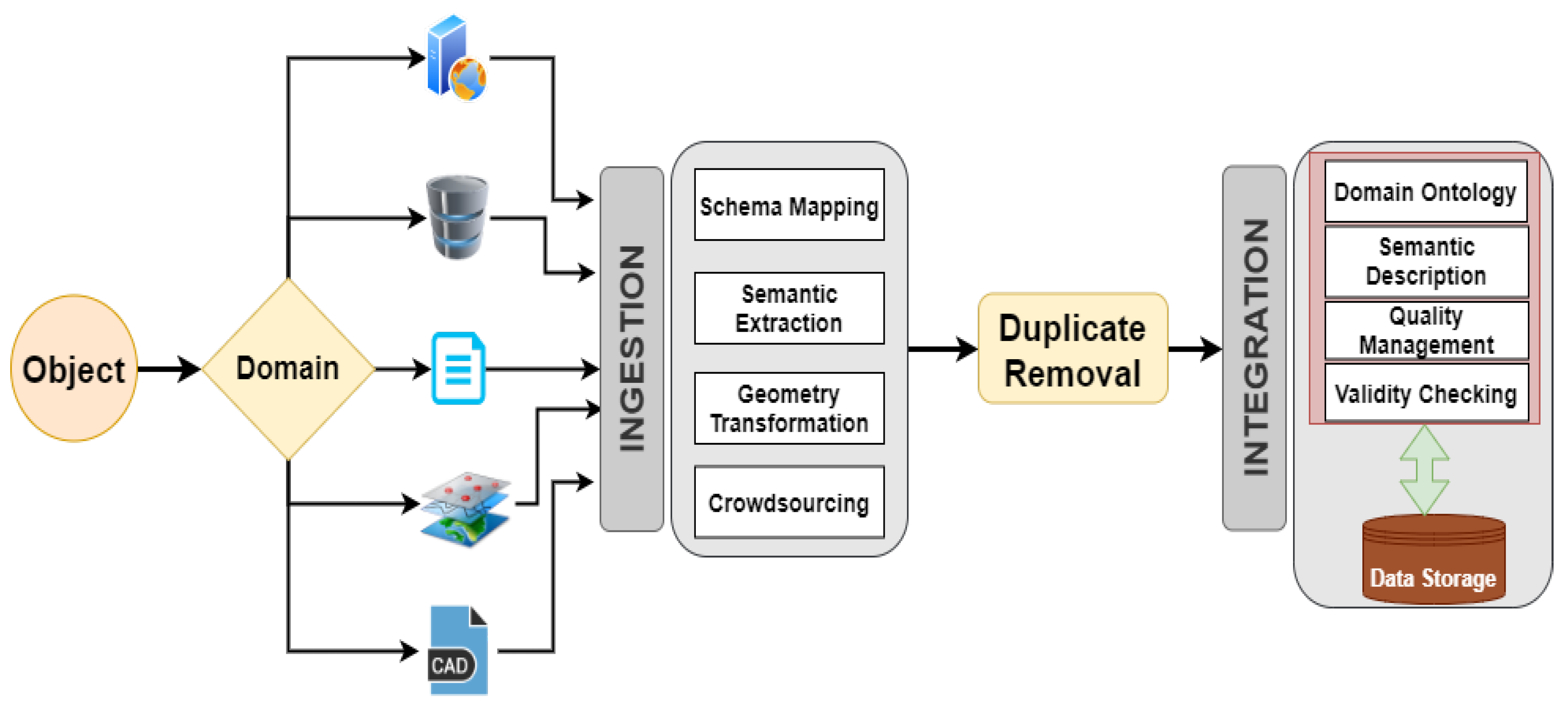
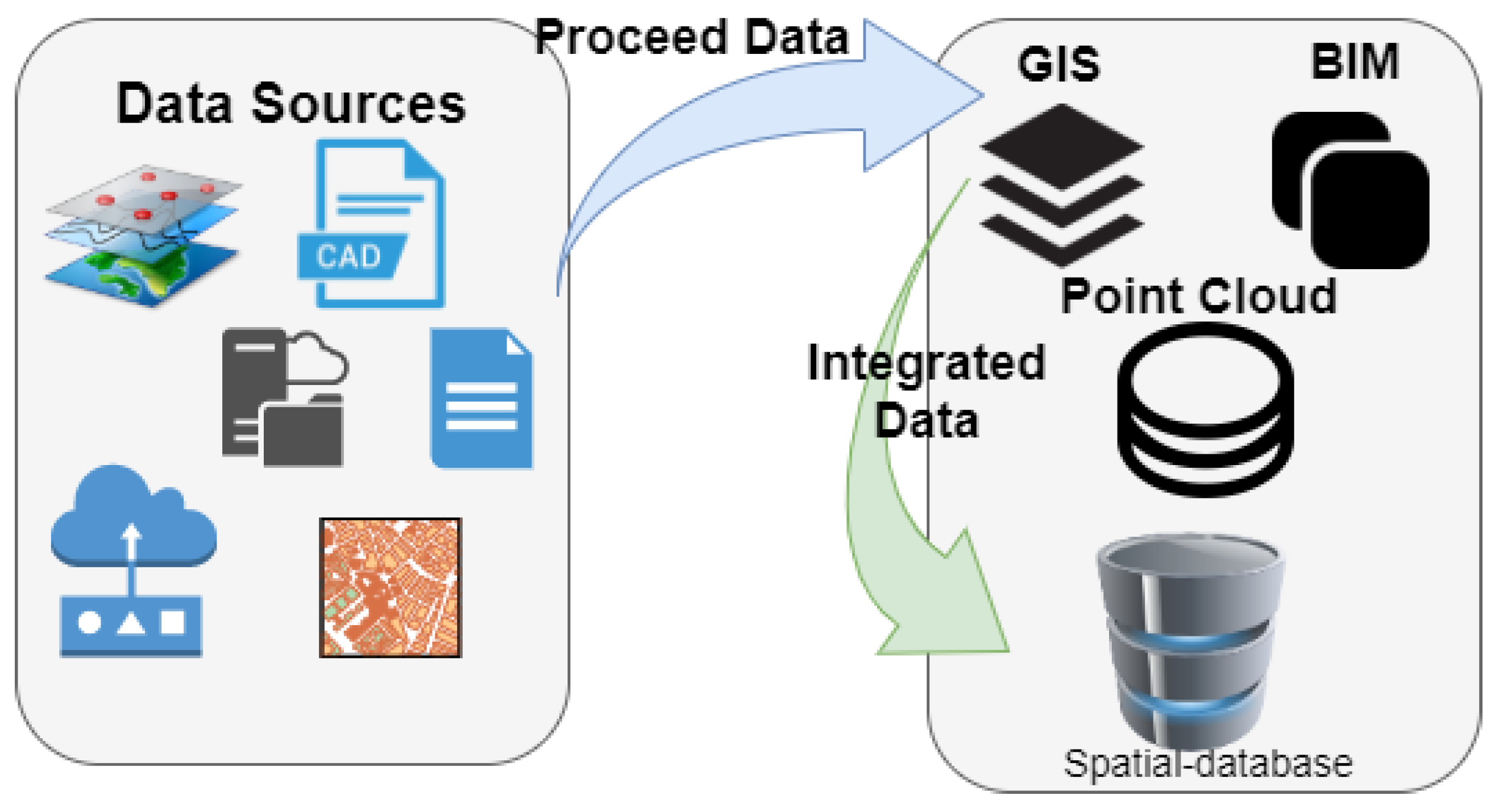
  • A novel perspective on PIM is proposed considering multi-source heterogeneous data for the sake of improving the potential values and interpretation performance of the built environment at campus scale.
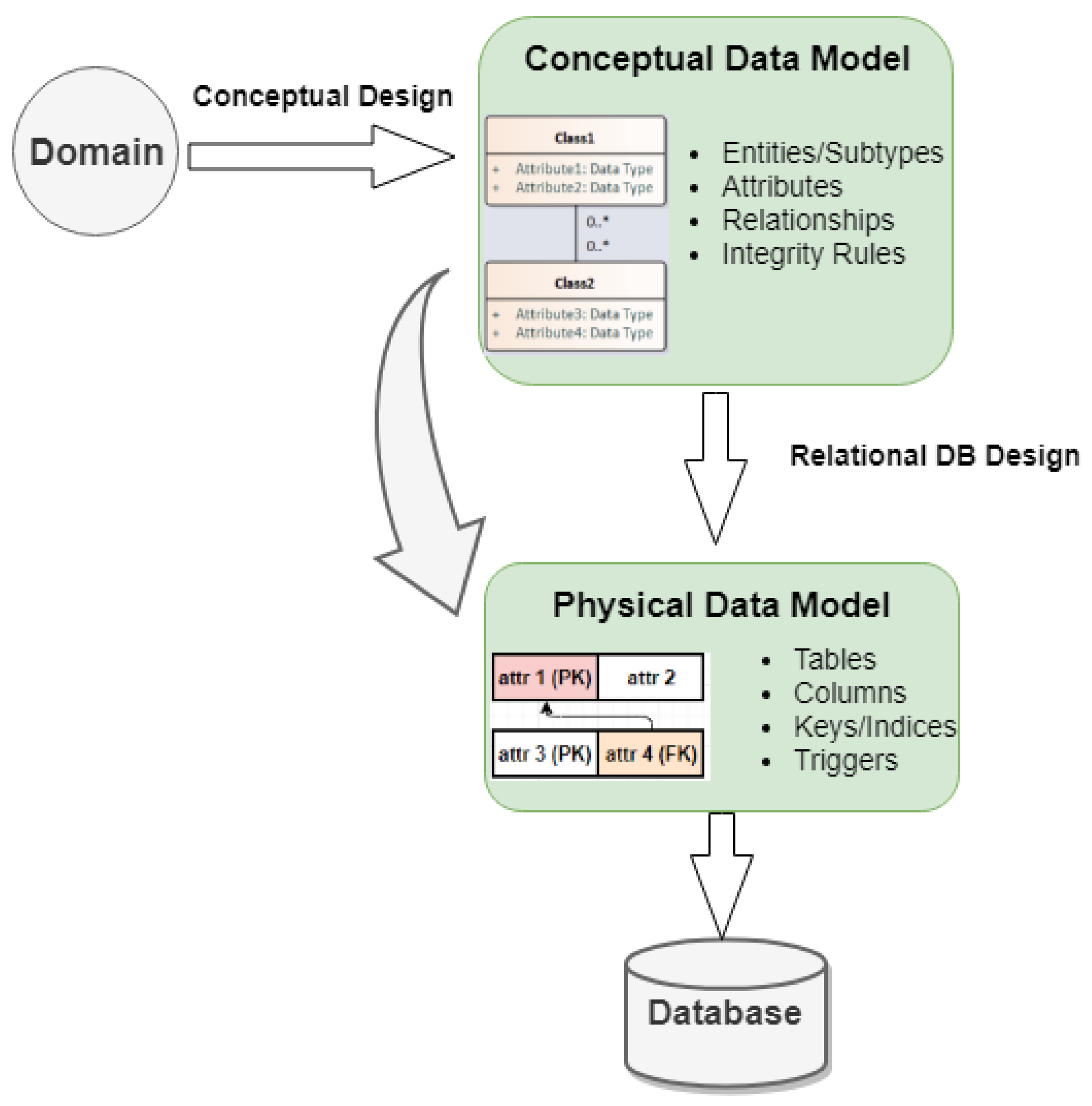
  • A general conceptual design and relational database design has been developed for unified 3D city model in an integrating manner.
  • A usability analysis of our SDBMS solution through a real-world campus model.

1.3. Organization

The rest of this paper is structured as follows: Section 2 gives a brief retrospect to the 3D city models and data fusion. In addition, the essential aspects and approaches for geo-data modeling using spatial DBMS are discussed to provide the foundation for designing a unified and compliant relational database schema for PIM. Section 3 and Section 4 presents our PIM fusing multi-source heterogeneous data (GIS, BIM, LiDAR and sensor) with details about the conceptual design and relational database design. A case study on the UNSW campus to demonstrate the usability and efficiency of our model is shown in Section 5. The last section draws the conclusions about the presented work and outlines the relevant aspects of our future research and developments tasks.

2. Background and Related Work

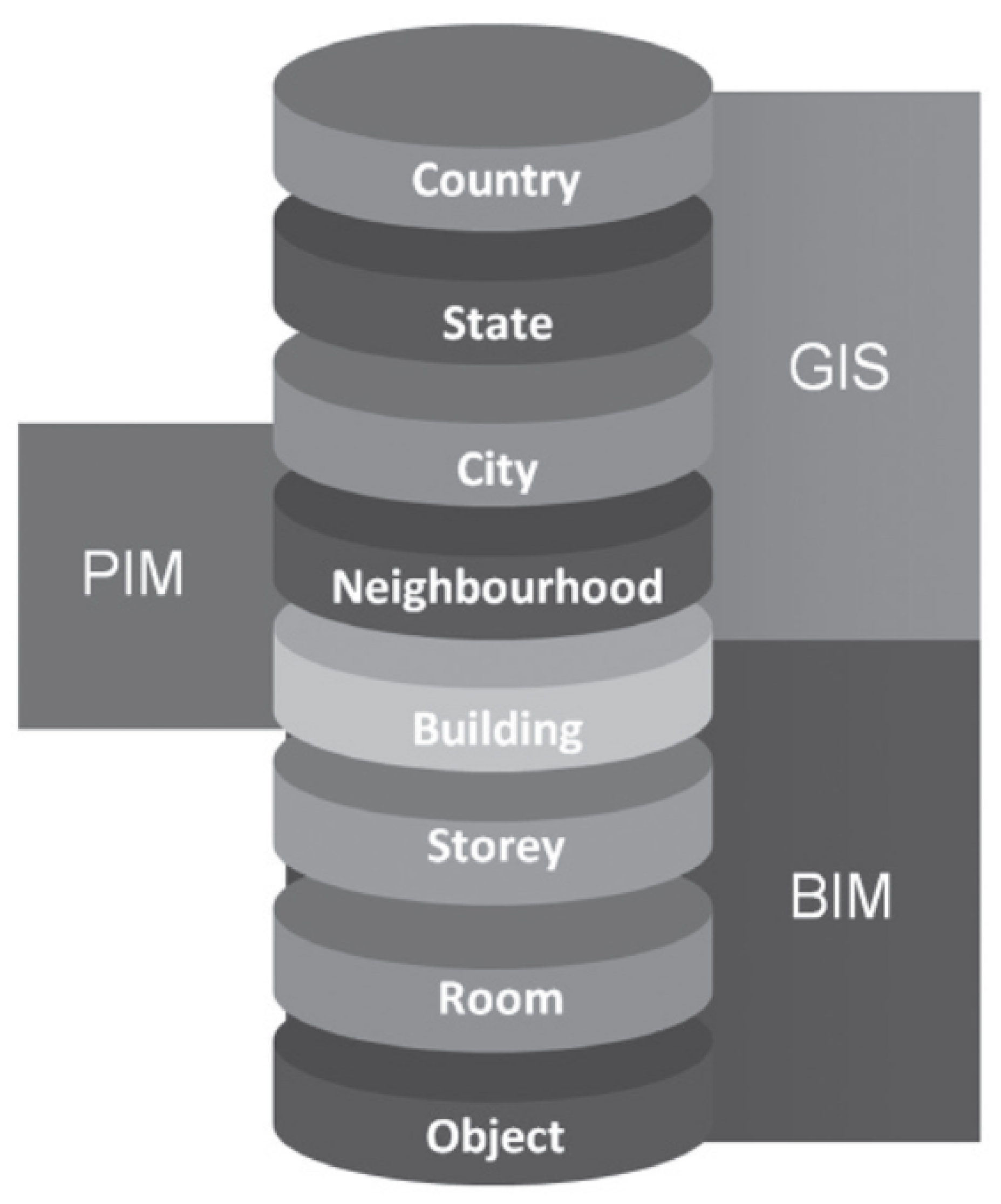
2.1. 3D City Models and PIM

A 3D city model is a representation of an urban environment with a three-dimensional geometry of common urban objects and structures, with buildings as the most prominent feature [1,19,20]. Seemingly, visualization dominated the early uses of 3D city models. However, as technology developed, 3D city models have become valuable for several purposes beyond visualization, and are used in many domains (e.g., visibility analysis, 3D cadaster, infrastructure planning, indoor navigation, energy demand estimation). Because each 3D application requires its own specific 3D data, a comprehensive inventory can help to link the requirements to specific applications. The urban design spans planning and architecture as well as the GIS-BIM information and modeling environments, operating primarily at the precinct scale. Precinct Information Modeling (PIM) is proposed in 2013 [10] as the central to this scale of urban innovation. As demonstrated in Figure 1, the spatial scales for built-environment modeling range from general objects to buildings and upwards to cities and countries. With the need for data interoperability, different types of information modeling application based on multiple scales (i.e., BIM -> PIM -> GIS) arose in recent years. Here, the scale we talk about in PIM is more about the scope of the modeling, while, the level of detail in CityGML and IFC indicate less or more detail of the same object regarding both their geometry and thematic.

2.2. Smart Built Environment and Data Fusion Opportunities

With the emergence of the concept of “Smart Built Environment”, which refers to a built environment that has been embedded with smart objects, such as sensors and actuators, with computing and communication capabilities, making the environment sufficiently “smart” to interact intelligently with and support their human users in their day-to-day activities [21], researchers have explored how to design building models hosting multiple information throughout its life cycle and what is the benefit of harnessing BIM or GIS information and capabilities (see [22]).
Currently, an enormous amount of data is produced in a quick span of time in the built environment. How to make these multiple sources data precise and highly accurate is an open problem which needs to be considered since the quality of this information plays an important role in visualization, planning and decision-making. Data fusion [23,24], which is regarded as a part of data integration, is an effective process of integration of multiple data representing the same real-world object into a consistent, accurate, and useful representation. Figure 2 presents the paradigm of general data fusion. For example, there are several construction datasets for general building domain generated by different data providers. Data fusion aims to merge these datasets into a database with a consistent data schema, through a process of ingestion, duplicate removal and integration. The records (from different datasets) describing the same object, e.g., a commercial building, are generated in the same domain.

2.3. Geo-Data Modeling in Spatial DBMS

Spatial-database management system (Spatial DBMS) [14] is usually considered to be mainstream relational Database Management System (DBMS) with the extension which incorporates spatial data types and geometry, support for spatial indexes, and provides functions and operations for analysis and processing of spatial objects. Concepts developed in the fields of Spatial DBMS may be applied to both 2D and 3D geo-applications [7,25,26].
In a given spatial DBMS, data may be modeled in classes as parts of an object-oriented geo-model. Applications relying on geo-models have distinct needs: some applications may require models only for visualization, while others may require models for analysis and statistics. Defining implementations for geo-models that provide efficient storage and retrieval of the models in spatial databases received enormous attention from researchers. Mapping is often necessary to convert a conceptual geo-model used for visualization into a physical geo-model stored in the spatial database. The heterogeneity of current geospatial geometric and topological data models shows the importance of integration for spatial DBMS. Figure 3 presents an integrated spatial DBMS. For example, there are multiple data sources with different data formats, such as reports, images, maps, shapefiles. After data pre-processing, GIS, BIM and Point Cloud data with the spatial data type or geometry are stored in spatial databases.

2.4. CityGML and IFC Standards

Building Information Modeling (BIM) is a digital representation of a facility’s physical and functional characters [27]. It is based on technology incorporating information in three dimensions (3D) and integrates the necessary information required by Architecture, Engineering, Construction and Facilities Management (AEC/FM). In contrast, Geographic Information Science (GIS) is developed to manage and analyze spatial data, which is based on geomatics technologies. GIS as a technology/system allows the storage of spatial information in the relational database, and, as a science, is also beyond the data storage system. The attribute information associated with spatial features stored in the database allows for further spatial analysis using both the spatial and non-spatial attributes.
Due to wider availability of information, ease of analysis and for pragmatic reasons, the studies on the exchange of BIM and GIS data often focus on the two most prominent open standards in the two domains: the OGC standard CityGML [12] for the 3D GIS domain, and the Industry Foundation Classes (IFC) [13] for the BIM domain. IFC models represent the physical elements of single constructions in great detail, while CityGML models represent entire cities in a simpler format that is usable for exchange, dissemination and spatial analyses, such as solar potential and energy consumption estimations. The two modeling paradigms embodied by IFC and CityGML are representative of BIM and 3D GIS data in general, and they are both widely used in their respective domains.

2.5. Related Work for CityGML and IFC Integration

BIM and GIS interpret 3D modeling from two different perspectives: GIS focuses more on real-world modeling, while BIM is more focused on the design process. Therefore, in CityGML, for example, a wall is represented as the surface for each room separately, while in IFC, a wall is a volume object, which is shared between rooms and the exterior shell [28]. The real-world modeling of GIS is driven by the requirements of mapping tasks, while the design modeling of BIM is based on the representation of geometric design and construction details [29]. Considering buildings, GIS often focuses on the geographical information and shape of buildings and building components from a geographical perspective. In contrast, BIM often focuses on the detailed building components, such as architecture and construction perspective [30]. With the recent demand for merging outdoor and indoor applications [31] for different purposes, attempts have been made to design methods and tools to integrate building models within a geospatial context.
The integration system of BIM and GIS enables the effective management of information in various stages of a project’s life cycle, namely planning, design, construction, operation, and maintenance [17]. The information at any spatial and temporal scale can be available in such a system for different applications. Effective management of heterogeneous information from different sources can also provide essential supports for decision-making.

3. Precinct Information Modeling (PIM) with Data Fusion

In this section, we describe spatial database solution for a high-level unified model at the precinct scale with multi-source data fusion which encapsulates both the CityGML and IFC standards. The following subsections explain the process of data modeling. Important design decisions are pointed out. The two main steps are marked as conceptual design and relational database design in Figure 4.
  • A Unified Model at Precinct Level (Section 3)
    To achieve a more compact database schema and improve query performance, the CityGML and IFC model are combined into a simple and unified model at some critical points.
  • Derivation of the Relational Database Schema (Section 4)
    The unified object-oriented data model has been mapped to relational tables. The number of tables were optimized to minimize the number of joins for typical queries.
Design decisions in the model are explicitly visualized within the UML diagrams. To enhance the readability of the UML diagrams, classes are depicted in different colours if they belong to different standards/models. The following colouring scheme is applied:
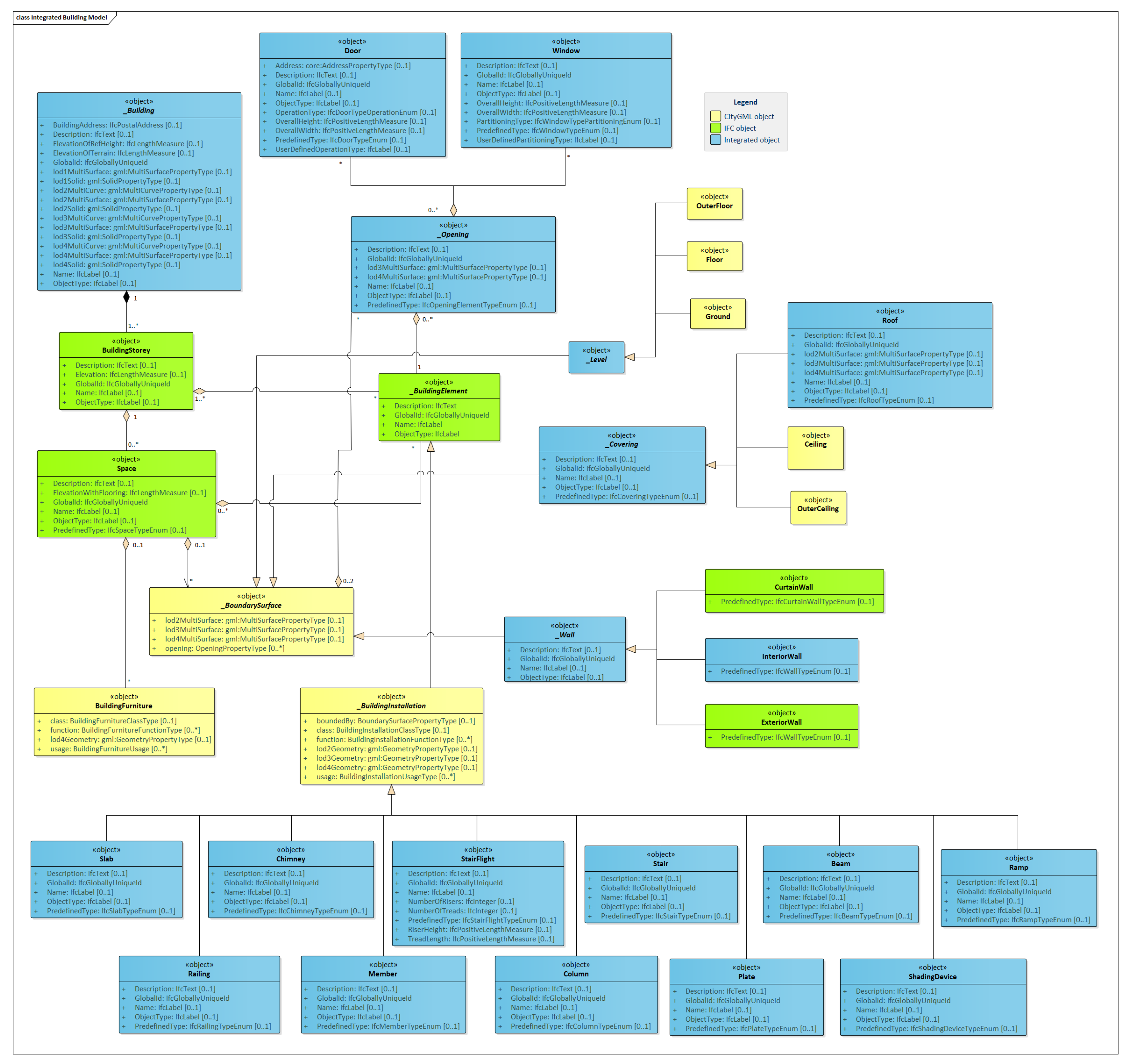
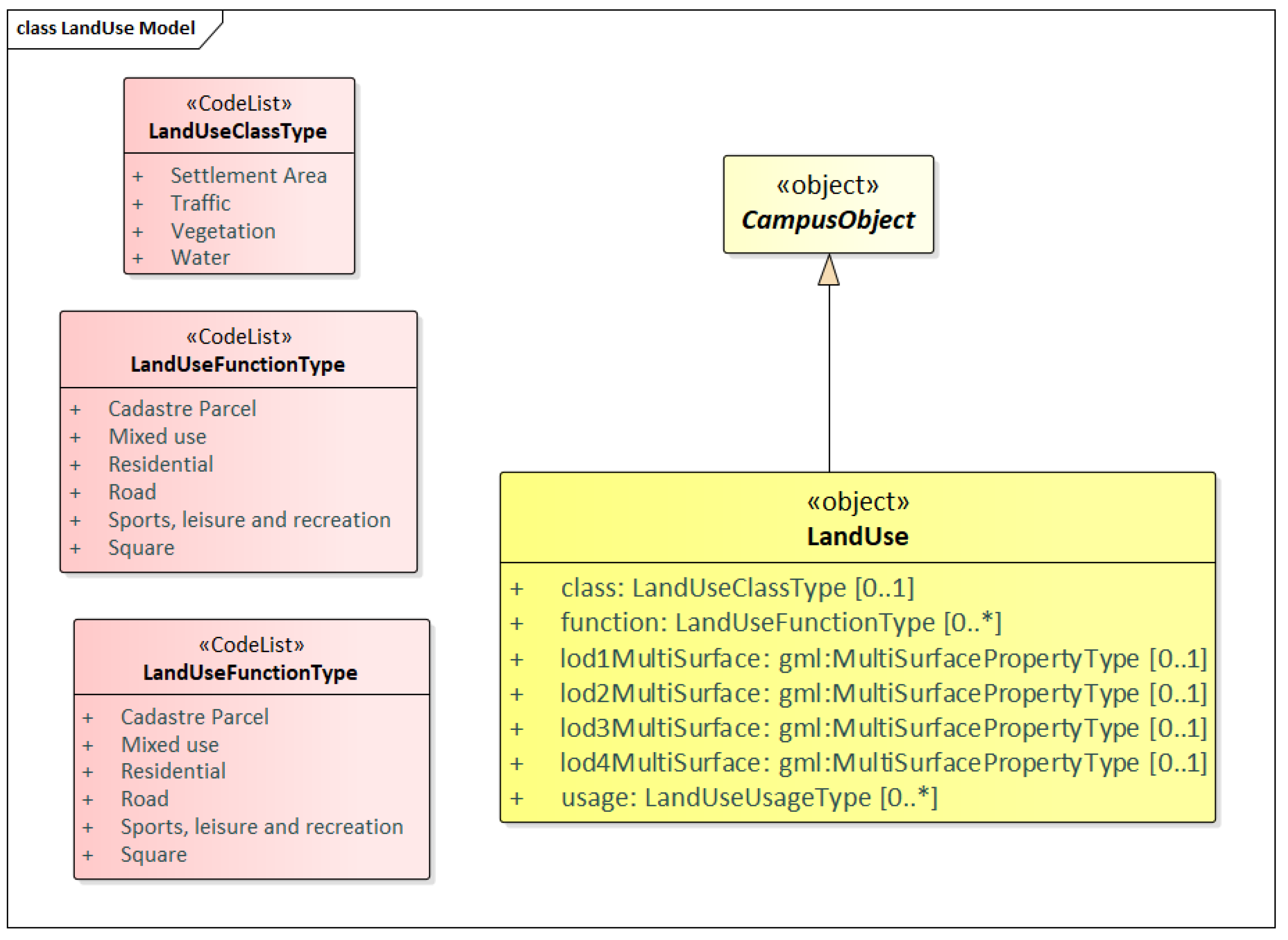
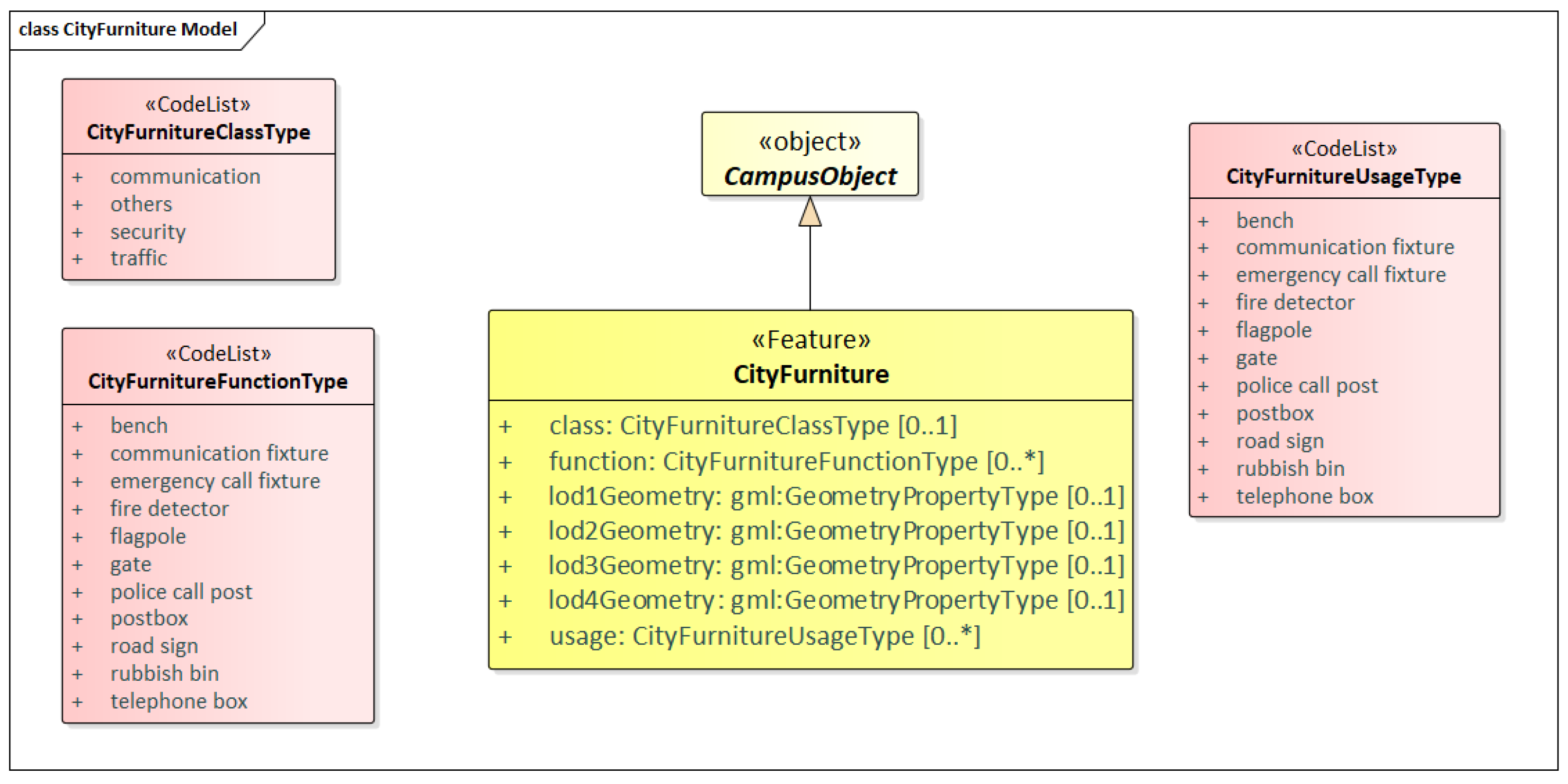
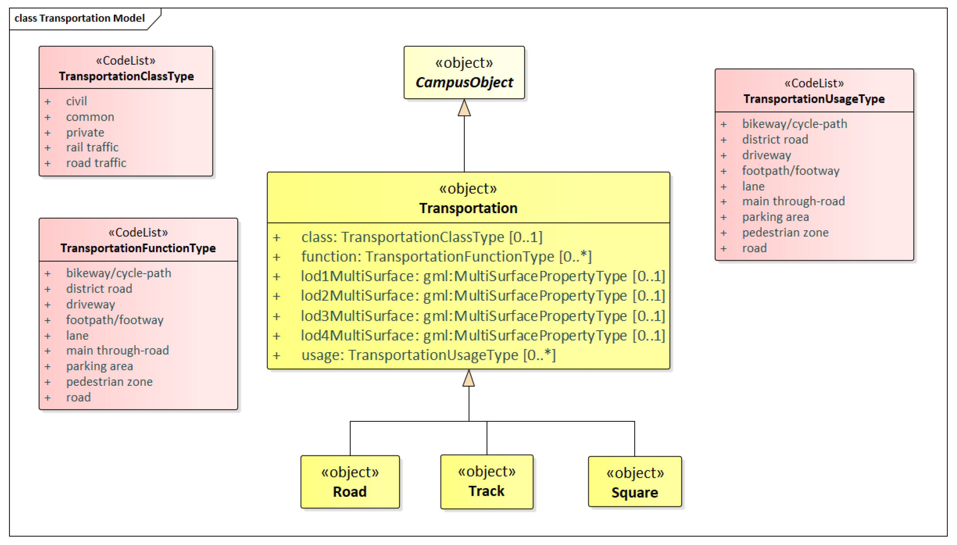
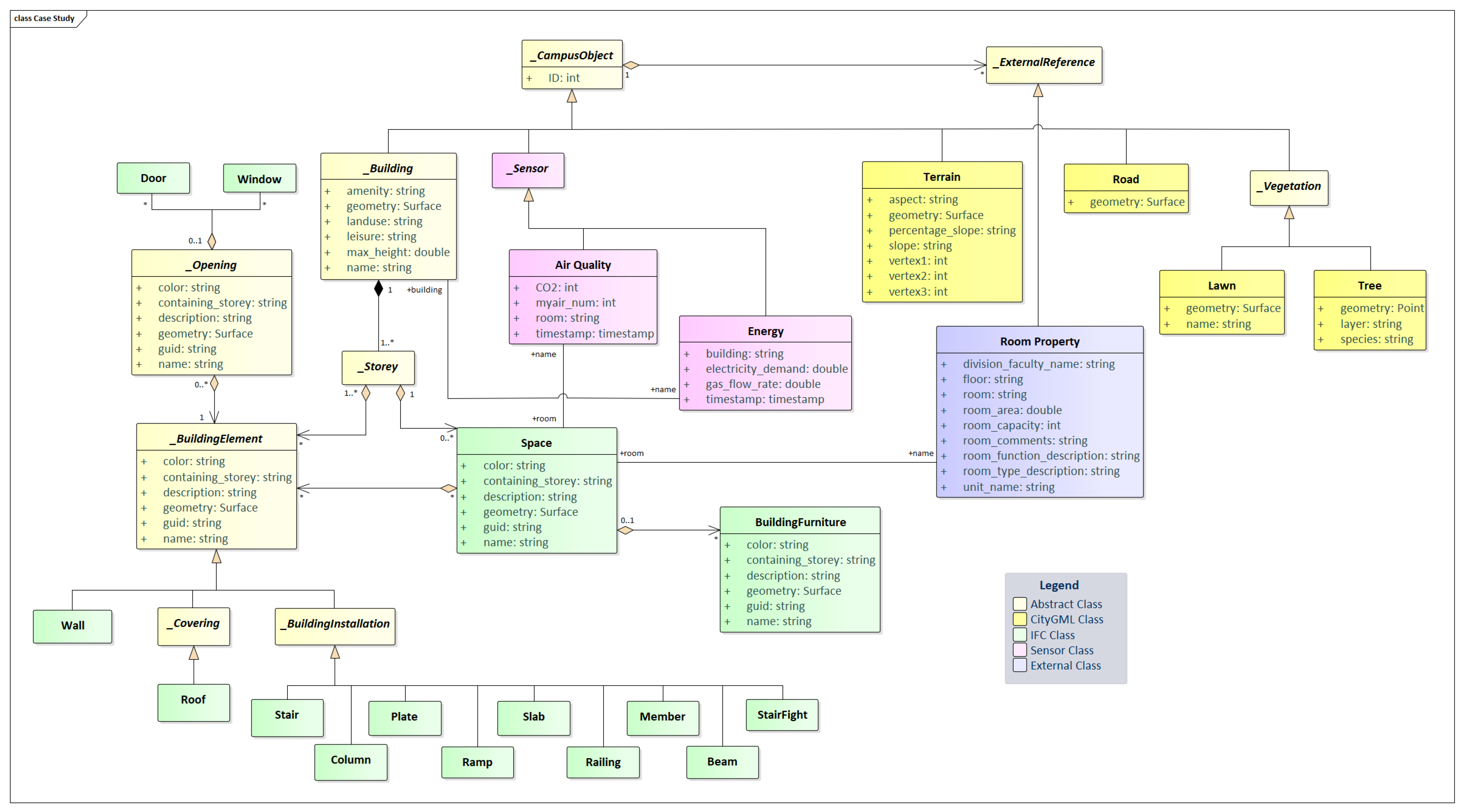
  • Classes painted in YELLOW belong to the pure CityGML model which is subject of discussion in the following subsections.
  • Classes painted in GREEN belong to the pure IFC model.
  • Classes painted in BLUE are integrated objects from both IFC and CityGML model which are defined in Section 3.2.1.
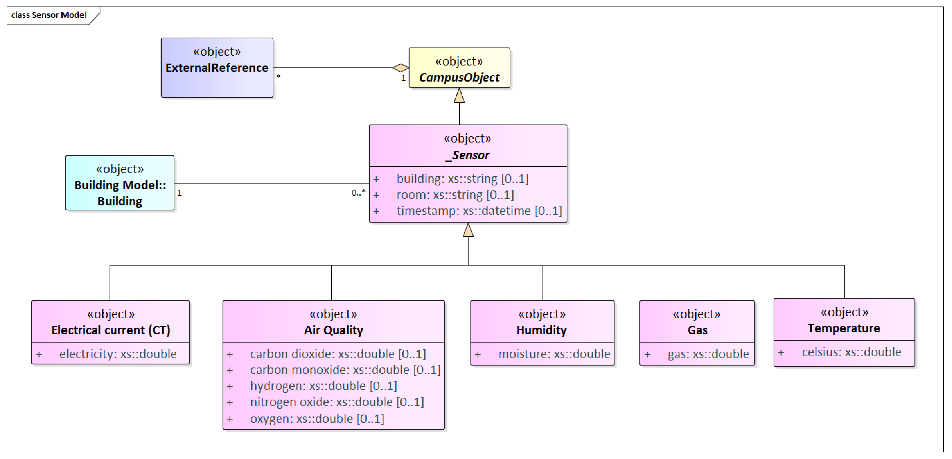
  • Classes painted in PINK are from sensor data, such as gas and electricity.

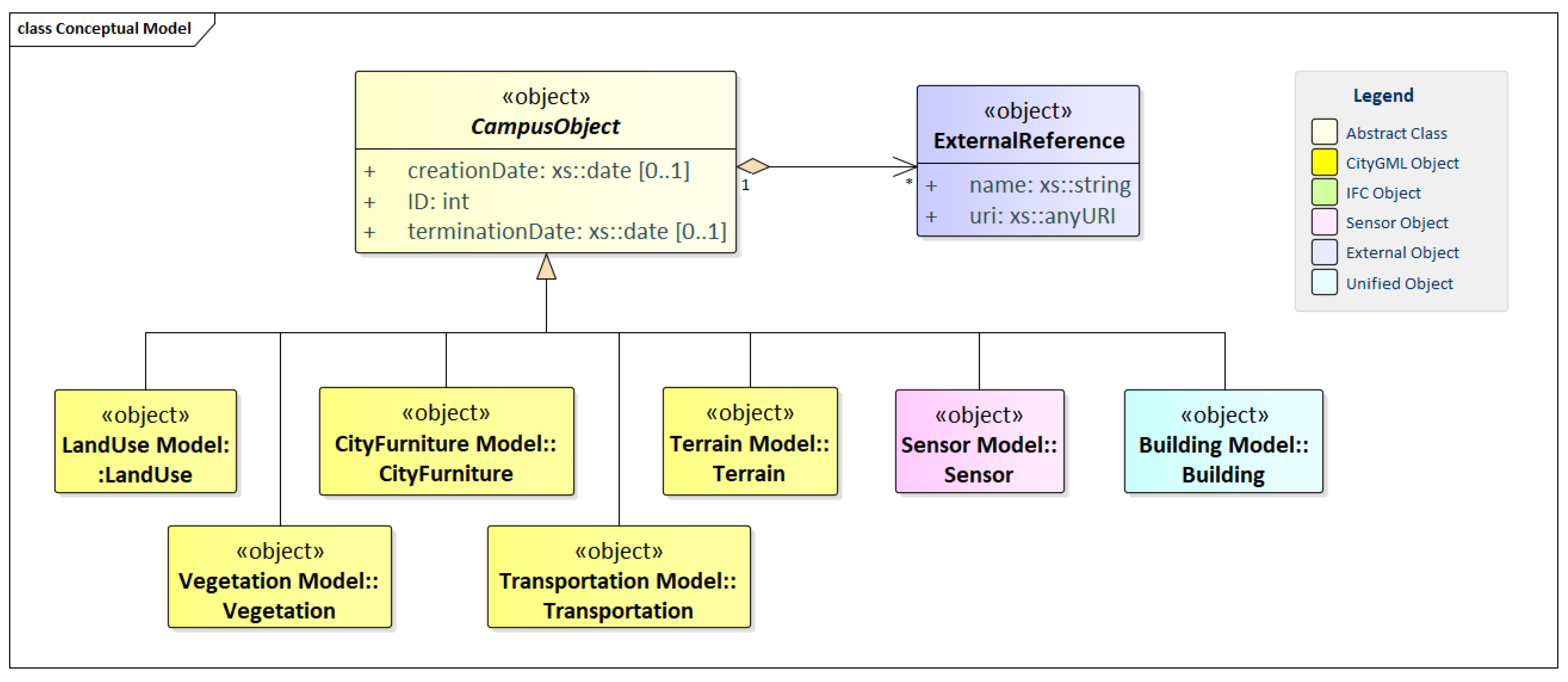
3.1. Conceptual PIM at Campus Scale

The design and management of our 3D campus model generally focus on two aspects: architecture and sensing. The architecture refers to that provided by our model to support the lifecycle of a construction project, including plan, design, construction, operation, and dismantling, also provide analysis and visualization of location-based services. Thus, we adopt the IFC model which includes building structures and appearances, as well as CityGML model which is used for spatial analysis based on the functional and physical relationship of the outdoor environment. On the other hand, sensing is considered to be one essential component of our campus model. Room/Building-based sensor-driven services can come into being and stakeholders can make use of the outcome of sensor-driven services to trigger more services, enhance or improve the current design to use resources more wisely. Our novel unified 3D campus model hosts the collaborative architectural information and provides the semantic knowledge of the campus. With the emergence of smartly built environment tendency, our model should be further developed to be capable of seamlessly integrating smart objects in campus design and feed objects with relevant building-related information.
In this section, our slightly unified 3D campus model with respect to CityGML and IFC models is described at the conceptual level using UML class diagrams. This diagram forms the basis for the implementation-dependent realization of the model with a relational database system. Figure 5 shows the conceptual design of our integrated model where different colors are used to represent different class definitions for the most important types of objects within virtual 3D campus models which are briefly described below. Following categories are presented in this integrated campus model:
  • Building
  • Sensor
  • City furniture
  • Terrain
  • Transportation
  • Vegetation
  • Land use
The aim of explicit modeling is to reach a high degree of semantic interoperability between different applications. By specifying the thematic concepts and their semantics along with their mapping to UML, different applications can reply on a well-defined set of object types, attributes, and geometries. The base class of all thematic classes within our data model is the abstract class CampusObject, which provides a creation and a termination date for the management of histories of objects as well as generic attributes and external references to corresponding objects in other data sets. Such a reference named ExternalReference denotes the external information system and the unique identifier of the object in this system. The subclasses of CampusObject comprise the different thematic fields of a campus model, in the following covered by separate models: building model (Building), city furniture model (CityFurniture), digital terrain model (Terrain), land use model (LandUse), transportation model (Transportation), vegetation model (Vegetation), and sensor model (Sensor). In terms of specific class Building, it covers both IFC and CityGML building models (The detail of these two separate models can be found in Appendix A and Appendix B).

3.2. Building Model

3.2.1. Integrated Building Model (IBM)

Building model is the class capturing information about spatial structures and building objects from both BIM and GIS data in our 3D campus model. It can also facilitate modeling a database schema that can carry data that is required for all level of details (LODs). The Integrated Building Model (IBM), therefore, used as the integrated model for importing pure IFC and CityGML building model provided by different stakeholders. Also, we present our methods for converting objects from IFC and CityGML to those in the proposed IBM (see Figure 6).
To build an integrated building model, all classes with their concepts are collected from both CityGML and IFC models. Overlapping concepts are merged and therefore new objects need to be created in such a way that objects from both models can be captured. Figure 6 shows the integrated building model, which is briefly described below.
Based on the CityGML model, the building model allows the representation of simple buildings that consist of only one component, as well as the representation of complex relations between parts of a building. Therefore, it provides the subclass Building and BuildingPart of the pivotal class _AbstractBuilding. However, in the IFC model, only one class, IfcBuilding is used for representing the basic building structure. For convenience, we create a unique class Building that merges concepts of IfcBuilding and _AbstractBuilding to denote simple or complex buildings.
Based on the IFC model, a building is used to provide a basic element within the spatial structure hierarchy for the components of a building project together with site, storey, and space. Therefore, a building must have at least one storey (named BuildingStorey in IBM) which has an elevation attribute as a local height value relative to the top of the construction slab. A space in IFC represents an area or volume bounded actually or theoretically within a building. However, a building in CityGML consists of rooms which can be regarded as a space surrounded by different boundary surfaces. Therefore, we create a class Space which copies IfcSpace object. We link LOD2 to LOD4 boundary surface objects _BoundarySurface with space object, where boundary surfaces are used for structuring the exterior shell of a building and visible surfaces of a room. Both IFC and CityGML contain opening object; however, in CityGML it is the abstract base class for semantically describing openings like doors or windows (rf. Figure 7), while the opening element in IFC represents a void within any element that has physical manifestation and it has to be inserted into an IfcBuildingElement like IfcDoor and IfcWindow. Here, we create an abstract class _Opening including attribute list in IfcOpeningElement, and two specific class Door and Window. _Opening objects in IBM only exist in models of LOD3 or LOD4 and each one is associated with a gml:MultiSurface geometry.
Building element comprises all elements that are primarily part of the construction of a building. However, elements in CityGML are not explicitly defined but they can be represented as an explicit aggregation of IntBuildingInstallation and BuildingInstallation. In this case, we merge IntBuildingInstallation and BuildingInstallation into one abstract class called _BuildingInstallation, which is used for building elements like balconies, chimneys, dormers or outer stairs, strongly affecting the outer appearance of a building, and objects within a building which (in contrast to furniture) cannot be moved. A _BuildingInstallation may have the attributes class, function, usage, and geometry.
Considering building elements, we create an abstract class named _BuildingElement which contains several subclasses. To be able to populate them, we need to reorganize objects from CityGML and IFC belonging to the interior or exterior building installations. In IFC, there is a class named IfcBuildingElement which includes all elements that are primarily part of the construction of a building. We divide them into different classes based on the concepts of IntBuildingInstallation and BuildingInstallation in CityGML. In this case, building elements like chimney, column, stair, railing which exists in both model and we can combine them into one unified class like Chimney, Column, Stair, and Railing. In addition, other elements only in IFC while belong to building installation (such as Slab, StairFlight, Member, Beam, Plate, Ramp) are to be also added as subclasses of _BuildingInstallation in IBM.
Moreover, room furniture, like tables and chairs, can be represented in the CityGML building model with the class BuildingFurniture. A BuildingFurniture may have the attributes class, function, usage, and geometry. A BuildingFurniture object should be uniquely related to exactly one room object. However, in IFC, movable part of a building, such as a chair or furniture, are not been considered. Therefore, we straightforward create class BuildingFurniture from CityGML model in IBM. All the geometry of the interior of a building is in LOD4, the highest level of resolution. We can regard BuildingFurniture as the subtypes of new _BuildingElement class and only accept objects from CityGML building model.
For other building elements not belonging to class _BuildingInstallation, we have defined some new concepts in such a way that all concepts from both IFC and CityGML can be covered. The difference between these building elements in CityGML and IFC is the representation of different surfaces, interior and exterior parts of a building (wall, covering and ground). Figure 8 shows the classification of _BoundarySurface in CityGML of the outer building shell. Because of the need for different LOD representations and definitions of elements, such as (roof, ceiling) and (ground, floor), we have defined the building elements as follows:
  • _Wall is a vertical/semi-vertical element that surrounds or subdivides spaces. It has three subtypes:
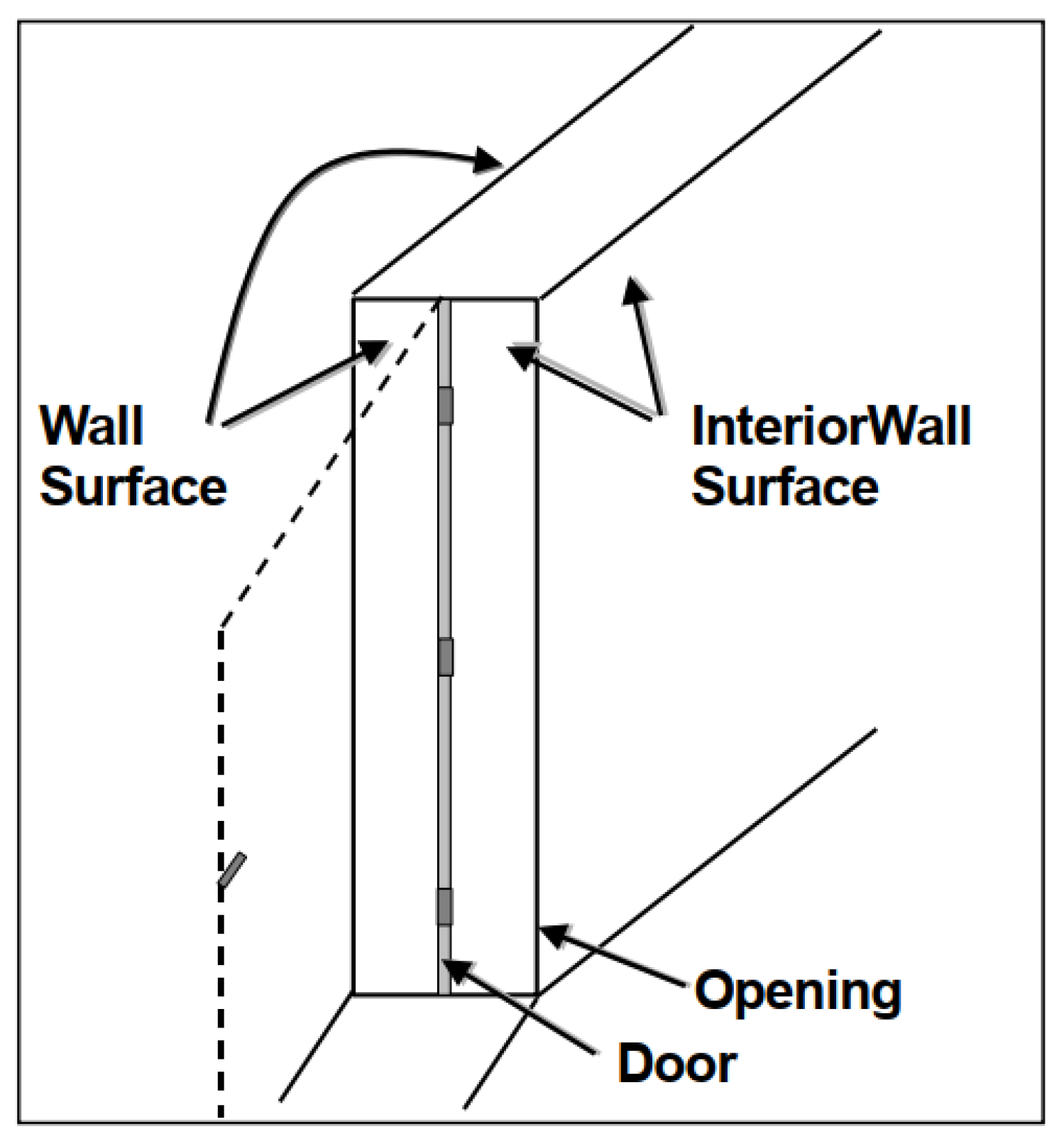
    InteriorWall for an internal wall between rooms or spaces (none of its faces has connection with the outer environment);
    ExteriorWall for an external wall that has connection with the outer environment and represents a part of external facades of a building;
    CurtainWall for the outer wall that covers a complete facade of a building or a part of it.
  • _Covering is a closing level that covers a space from the top side. It has three types:
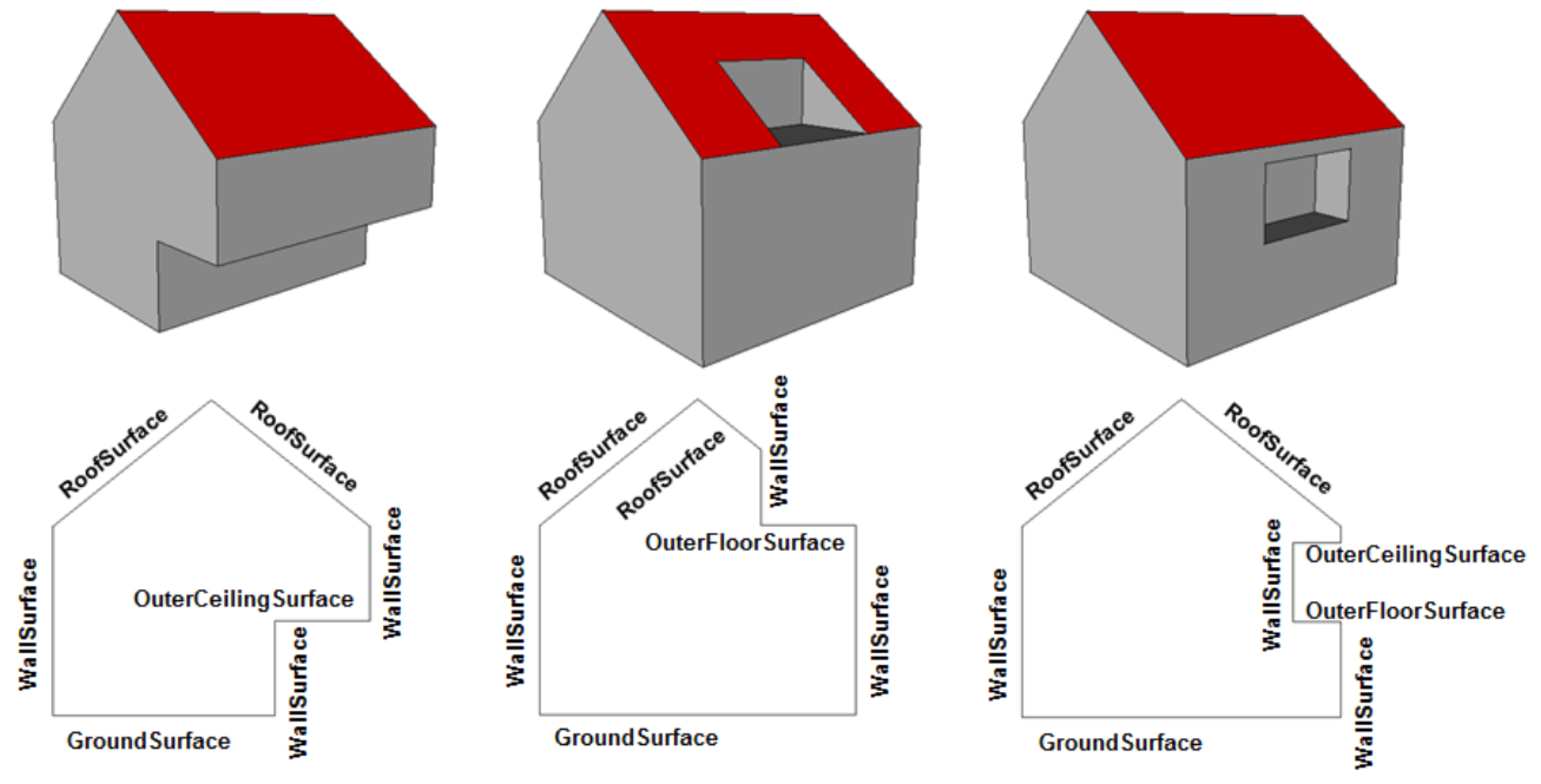
    Roof for the top covering of a building or the top storey which gives the external shape of a building from above;
    Ceiling for the internal covering of any space in a building;
    OuterCeiling for the external covering.
  • _Level is a walkable (not only horizontal) level that represents the bottom level of a space. It has three types:
    Ground for the bottom level of ground floor which has a connection to the outer ground to give the external shape of a building from the bottom level;
    Floor for the bottom level of a space in any space of a building except the bottom (lowest) storey;
    OuterFloor for the horizontal surface belonging to the outer building shell and with the orientation pointing upwards.

3.2.2. Conversion from IFC & CityGML to IBM

In this section, we present our method for converting IFC & CityGML to our integrated building model. First, we define a set of rules which describe how the objects in our integrated building model can be produced from both IFC and CityGML models.

From IFC to IBM

Transformation rule from IFC to IBM. Usually, IFC model is used for representing the detail of internal part of a building, which can be regarded as the supplement to the architectural details. Therefore, we only consider IFC model in the LOD3 and LOD4 of IBM.
At LOD3, parts of external objects and internal elements of building structure are represented. The information needed for BuildingStorey and Space can directly be acquired from IfcBuildingStorey and IfcSpace. In IFC, we have building elements (IfcBuildingElement) and opening elements (IfcOpeningElement). An IfcOpeningElement must be inserted into an IfcBuildingElement by using the IfcRelVoidsElement relationship. It may be filled by an IfcDoor, IfcWindow, or another filling element by using the relationship IfcRelFillsElements. Geometric information about doors and windows are defined as Sweeping and CSG models as other building elements (e.g., walls and slabs). In our proposed model, we adopt BRep geometry for opening elements as in CityGML. Therefore, conversions from Sweeping/CSG geometric models that are used in IFC to BRep models need to be performed.
At LOD4 of the IBM, all objects of a building structure, i.e., building elements (interior wall, ceiling, floor, etc.), building furniture, boundary surface are represented. As all IFC objects, Sweeping/CSG geometry is used for spaces and their elements which requires conversions to BRep geometric models that we use in the IBM. To create spaces in the UBM, information from IfcWall, IfcRoof and IfcSlab that form the boundaries of rooms are used. It is important here to mention that information of all building elements that form a space is stored in _BuildingElement class.

From CityGML to IBM

Similar to the conversion from IFC to IBM, we define a set of rules that describe how the objects in our model can partially be produced from CityGML model. The rules are given in the following description for different level of details.
At LOD1, a building model consists of a generalized geometric representation of the outer shell. Due to no information needed from IFC at this level of detail, _AbstractBuilding object can directly be conformed as Building object in IBM and it may carry gml:MultiCurve and gml:Solid geometries to cover the outer shell.
At LOD2, the exterior shell of a building starts to be decomposed into details. CityGML _BoundarySurface represents the base class for all other objects that form a building shell. At this LOD, the only needed details are about: (i) the _Covering of a building and shapes of its roof and outerceiling (from RoofSurface and OuterCeilingSurface); (ii) the _Wall of a building and surfaces of its exterior walls with their details (from WallSurface); and (iii) the _Level of a building and shapes of its ground and outer floor (from GroundSurface and OuterFloorSurface). In IBM, we keep the same geometric model as that of CityGML (only consider the BRep), so there is no geometry conversion during this phase. For building installations, the concept in the IBM is very close to that of CityGML. Therefore, we can use one-to-one mapping of the BuildingInstallation geometries into _BuildingInstallation geometries.
LOD3 denotes architectural models with detailed wall and roof structure potentially including doors and windows. Information about objects that share the same horizontal level in one building storey (or may be based on user definitions) can be aggregated to form BuildingStorey. BuildingStorey geometrically describes by all spaces that share the same floor surface. These spaces will be referenced from their boundary surfaces of RoofSurface, WallSurface and GroundSurface which define the external shell of each storey. At this LOD, opening elements should also appear in the model. Our concept of opening elements is similar to that of CityGML as door and window are subclasses of the class opening. Therefore, one-to-one mapping can be done between _Opening, Window and Door into corresponding classes in the IBM.
LoD4 represents the highest detailed LOD in which all the building elements, exteriors and interiors, should be represented. For building furniture, we can directly perform one-to-one mapping from BuildingFurniture in CityGML to BuildingFurniture in IBM. For _BoundarySurface, at this LOD, the needed interior details are about: (i) the _Covering of a building and shapes of its interior ceiling (from CeilingSurface); (ii) the _Wall of a building and shapes of its interior wall (from InteriorWallSurface); and (iii) the _Level of a building and shapes of its floor (from FloorSurface). Information about building elements is stored in different subclasses of the _BuildingElement class. Among them, for some objects belonging to building installations (such as chimney, column, stair, railing), we map them from IntBuildingInstallation to into corresponding subclasses of _BuildingInstallation in IBM. In addition, if the above subclasses have been created by IFC model, we need to merge them together by importing geometries and specific attributes into existing ones. We provide the set of conversion rules in the form of a table (Table 1).

3.3. Sensor Model

The sensor model contains several different data sources without explicit geometry as shown in Figure 9, which are donated by abstract classes _Sensor shown in UML diagram. There are various types of sensor available, in which building, room, and timestamp are common attributes. Among them, temperature sensors measure heat to detect changes in temperature, which may have Celsius attribute representing a scale of temperature. Humidity sensors are used to measure the amount of water vapor in the atmosphere. Gas and Air Quality sensors are used to monitor gas consumption and changes to air quality, including carbon dioxide, carbon monoxide, hydrogen, nitrogen oxide, oxygen. Electrical current (CT) sensors measure real-time energy consumption at a circuit, zone or machine level. Knowing how much energy is being used has two main uses. First, one can identify where you use and waste the most energy, allowing you to make savings. One can also automatically switch off assets when they are not in use. These sensors may have a piece of textual information where they are located (room, building, street), or in some cases even x, y, z coordinates of the measuring unit.

3.4. LandUse Model

LandUse objects describe areas of the earth’s surface dedicated to specific land use. They can be employed to represent parcels in 3D. Figure 10 shows the UML diagram of land use objects.
Every LandUse object may have the attributes class (e.g., settlement area, industrial area, farmland), function (e.g., cornfield) and usage which can be used, if the way the object is actually used differs from the function. Since the attributes usage and function may be used multiple times, storing them in only one string requires a single while space as unique separator relational database schema. These three attributes are specified as gml::CodeType. The values of these properties can be enumerated in code lists (which are painted in green in UML diagram). The LandUse object is defined for all LOD 1–4 and may have different geometries for each LOD. The surface geometry of a LandUse object is required to have 3D coordinate values. It must be a GML3 MultiSurface.

3.5. CityFurniture Model

City furniture objects are immovable objects like bollards, lanterns, flower buckets, advertising columns, or delimitation stakes. The UML diagram of the city furniture model is depicted in Figure 11.
The class CityFurniture may have the attributes class, function and usage. The class attribute allows an object classification like traffic light, traffic sign, delimitation stake, or garbage can, and can occur only once. The function attribute describes, to which thematic area the city furniture object belongs to (e.g., transportation, traffic regulation, architecture etc.), and can occur multiple times. The attribute usage denotes the real purpose of the city object, and can occur multiple times as well. The attributes class, function, and usage of the object CityFurniture are specified as gml:CodeType. The values of these properties can be enumerated in code lists. City furniture objects can be represented in city models with their specific geometry, but in most cases the same kind of object has an identical geometry. The geometry of CityFurniture objects in LOD 1-4 may be represented by an explicit geometry.

3.6. Transportation Model

The transportation model is a multi-functional, multi-scale model focusing on thematic and functional as well as geometrical/topological aspects. The main class is Transportation which represents, for example, a road, a track, a railway, or a square. In CityGML, transportation is composed of the parts TrafficArea and AuxiliaryTrafficArea which are some elements in terms of traffic usage or road, like car driving lanes, pedestrian zones, cycle lanes, kerbstones, middle lanes and green areas. In our campus model, we ignore both due to no such detail contents in generic campus. Transportation objects can be thematically differentiated using the subclasses Track, Road, and Square. The UML diagram of the transportation model is depicted in Figure 12.
Every Transportation object has the attributes class, function, usage, and geometry, referencing to the external code lists. The attribute class describes the classification of the object. The attribute function describes the purpose of the object like, for example, bikeway, driveway, footpath, while the attribute usage can be used if the actual usage differs from the function.

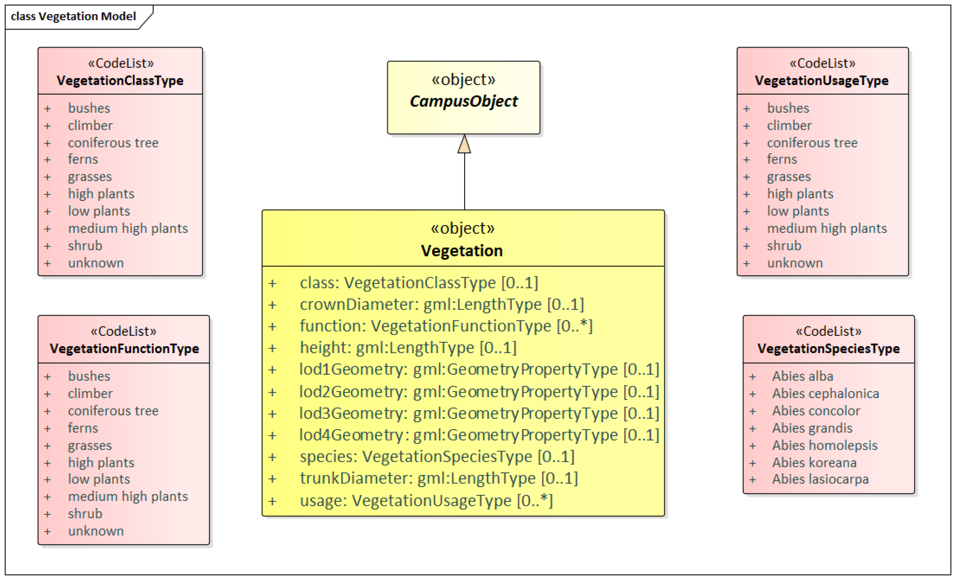
3.7. Vegetation Model
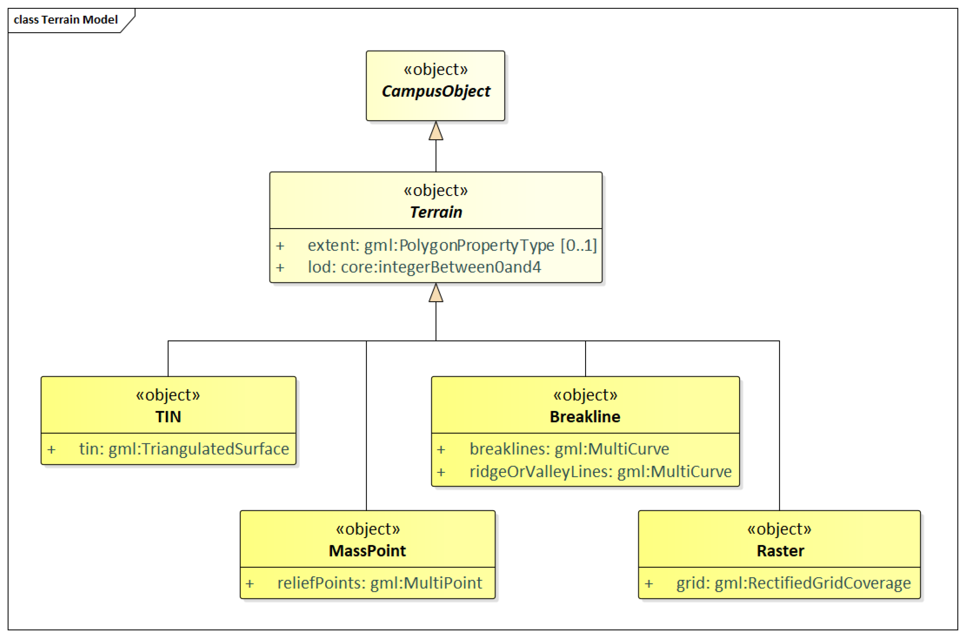
Vegetation features are important components of a 3D campus model because they support the recognition of the surrounding environment. By the analysis and visualization of vegetation objects, statements on their distribution, structure and diversification can be made. The vegetation model of CityGML distinguishes between solitary vegetation objects like trees and plant cover like forests. Meanwhile, in campus model, plant cover objects do not need to be considered and regard solitary vegetation as vegetation in a class named Vegetation. The UML diagram of the vegetation model is depicted in Figure 13.
A vegetation object may have the attributes class (e.g., tree, bush, grass), species (species’ name, e.g., Abiesalba), usage, and function (e.g., botanical monument). The geometry of a Vegetation maybe defined in LOD 1-4 explicitly by a GML geometry with absolute coordinates, associated with the gml::_Geometry class representation an arbitrary GML geometry.

3.8. Terrain Model

An essential part of a campus model is the terrain. CityGML includes a very adaptable digital terrain model (DTM) which permits the combination of heterogeneous DTM types (grid, TIN, break lines, mass points) available in different levels of detail. We redefine class Terrain to represent a DTM fitting our campus model. This is a CampusObject with LOD step that fits the DTM as an attribute. The UML diagram of the terrain model is depicted in Figure 14.
Individual geometrical types of the Terrain objects are defined by the four subclasses: breaklines, triangular networks (TINs), mass points, and grids (raster). Geometrically, the corresponding ISO 19107 or GML classes define these types: breaklines by a single MultiCurve, TINs by TriangulatedSurfaces, mass points by MultiPoint, and raster by RectifiedGridCoverage.

4. Database Solutions for PIM

As aforementioned in Section 2, spatial DBMS have been developed in response to new requirements for geo-information applications in recent years. Among them, employing spatial-extended relational database management systems (spatial-RDBMS) to store and manage complex building models will bring lots of benefits. On one hand, spatial-RDBMS support all kinds of spatial data types, spatial access methods and spatial query languages, as well as providing means for high-efficient spatial indexing structure and geometric and topological analyses. On the other hand, spatial DBMS play an important role in bridging the geometric modeling of manmade and natural geo-objects. Therefore, it is useful to provide geometric primitives such as points, line segments, triangles, and tetrahedrons for both manmade and natural objects to construct more complex objects consisting of surfaces and solids [7]. Therefore, spatial DBMS such as commercial software ORACLE Spatial/Locator and the open-source software PostgreSQL with PostGIS extension play a major role for 2D/3D geoscientific models [32] due to their extensive capabilities in handling 3D spatial data.
The conceptual solution for handling object-oriented data models like CityGML and IFC in spatial-RDBMS can be abstracted to solving the problem of mapping the object-oriented data model onto a relational data model. Following mapping rules are adopted in our relational database design procedure:
  • A class shall be mapped into one single table. The mapped table shall have at least one primary key column to store the object identifier which may be known as “ID” and must be unique within the table. Additional columns can also be added to the mapped table for storing the spatial and non-spatial attribute values of the respective class objects.
  • A foreign key constraint needs to be added in case of 1:1 or 1:N relationship. For each binary 1:1 or 1:N relationship type, we choose one of the relations and include as a foreign key in the chosen relation the primary key of another relation. It is better to identify the relation S that represents the participating at the N-side of the relationship type.
  • An associative table in case of M:N relationship shall be used to link the tables mapped from the associated classes. For each binary N:M relationship type, create a new relation to represent this relationship. Include as foreign key attributes in the chosen relation the primary keys of the relations that represent the participating relations; their combination will form the primary key of the chosen one.
  • A foreign key constraint or an associative table needs to be set for inheritance relationship. The inheritance relationship between two classes can either be implemented using a foreign key constraint to link the subclass and superclass tables by joining their primary keys or mapped to a table that represents the two inherited classes at the same time.
However, although these mapping rules allow mapping building model onto a relation database model, they may easily lead to a large number of database tables due to plenty of building objects (e.g., door, windows, slab, plate, wall and so on) in CityGML and IFC building models. In the meanwhile, different objects may have a completely different attribute list and vast attributes may have numbers of null values. Furthermore, this may result in lots of join relations when queries are requested. An analysis of the existing relational database systems indicated that a more compact database schema is much more efficient for querying and processing of large and complex-structured data to facilitate good performance when interacting with the database in a real-time application [33]. To reach this purpose, our database schema shall result from a careful manual process by identifying and simplifying the complex classes and data type and mapping them onto fewer tables with respect to the database interoperability. Concerning this requirement, the types of attributes are customized to corresponding database (PostgreSQL) data types (see Table 2).
Furthermore, we propose a set of fine-grained mapping rules:
  • Mapping classes in inheritance relationship or same hierarchy level into one table. We assume that in most cases, subclasses may have or set the same attribute list due to data missing or multiple unique attributes make no contribution to special applications. With this consideration, some classes belonging to an inheritance hierarchy can be mapped into one single table, which results in the retrieval of data in all subclasses just need to perform queries on one table in order to avoid multiple tables joins for speeding up the overall performance. This way, the single table allows for rapid retrieving a list of different objects through a query on the category attribute which distinguishes instances objects stored in the table from different types. For detail, we can add an additional column named “OBJECTCLASS_ID” or “OBJECTCLASS_NAME” which can store a numeric value or string value in each row for representing the respective class type.
  • Mapping aggregations and compositions into one table. Due to our building is objected-oriented, aggregation and composition relations of classes can be properly modeled by using a foreign key for joining each class with its parent class. For special case that recursion appears in aggregation or composition relationships, a single table for mapping of all the involved classes along with their inheritance relationship can be added in the database. For detail, we can add an additional column “PARENT_ID” as the foreign key which is used for representing the composition relationship.

5. Case Study

As a case study area, the UNSW campus is selected. Among all available data, we have concentrated on three types: GIS (e.g., 2D or 3D spatial data), BIM and sensors information. We do not have any complex shapes from IFC for the implementation since all IFC we have are B-reps. Most of the GIS data is mainly in 2D we reconstruct 3D objects from it. Rhinoceros (with Grasshopper) is used to process the entire reconstruction [34]. We import BIM (obtained as IFC files) models using the IFC++ library [35] and process the geometric, topological and semantic information using CGAL [36]. As the main source for data pre-processing, a terrain generated from point clouds is used. Thus, data representing BIM models, 2D floorplans, roads, green areas and trees are draped to the terrain.
The integrated 3D model is stored in an object-oriented database—PostgreSQL/PostGIS in our project, which can be remotely accessed via host address, port, and password. Data in our database can also be accessed via web requests, which allows external application developers to create either web-based or standalone applications that interact with relevant data entities in our model for particular purposes. Stakeholders are allowed to query and update their objectives against the existing precinct entities in our model.
Furthermore, QGIS software can be used for visualizing entities. It can open a model across the Internet connection to the database server, edit that model and save the amended model either to a model file on the local system or merge it back into the source model on the server. We have shown database access and query use cases in our conference paper [37] via customized datasets. Therefore, SQL-based queries experiments can be found in [37].

5.1. Conceptual Design

According to the general conceptual design for integrated 3D city model at campus-scale in Section 3.1, we develop our specific 3D model for UNSW campus based on the objects we have. In Figure 15, the subclasses of _CampusObject comprise the different thematic classes related to the built environment in UNSW campus, in the following covered by separate data models: building model (_Building), sensor model (_Sensor), transportation model (Road), vegetation model (_Vegetation), terrain model (Terrain) and external model (named _ExternalReference).
In detail, the external model receives information from UNSW ARCHIBUS Facilities Management System (https://archibus.unsw.edu.au/), which includes current attributes for floors and rooms with the intention to identify individual working spaces/desks, which plays as statistic data corresponding to each room in the building. Sensor model contains two different data sources which donated by classes Energy and Air Quality shown in the UML diagram as a subclass of _Sensor. Among them, Energy is a class which contains consumption of gas and electricity of each building in the UNSW campus, while air quality data of each room coming from MyAir system (https://citydata.be.unsw.edu.au/layers/geonode%3Amyair). The time interval is 15 s for both sensors. For transportation model, only road subclass exists in UNSW campus. Therefore, we omit superclass Transportation defined in Section 3.6, and replace it with unique class Road. Regarding vegetation model, we define one abstract class _Vegetation and two specific classes Lawn and Tree instead of representing specific objects in CodeList style as shown in Section 3.7. In terms of the terrain model, we process terrain objects in triangular networks (TINs) geometry. Thus, a concrete class Terrain which carries TINs geometry and its three vertices are created in our conceptual design.
The integrated building model is the most complex one consisting of both GIS and BIM data. Following the mapping rules defined in Section 3.2, we create one abstract class _Building donating building or building part from LOD1 CityGML data. _Building may have some attributes like name, max_height, landuse and so on. The building only has gml:LOD1MultiSurface geometry. To build connection between building object and energy sensor data, we add association between them via building name. The _Storey is an aggregation of building elements and spaces, and Space is a concrete class with attributes from IFC model. Due to no LOD2 to LOD4 boundary surface information in our CityGML model, here we simply regard space as room in the following experiments. Here, we add a link between Space and Air Quality through room name. IFC model also provides IfcFurnishingElement which is used as a generalization of all furniture related objects, we create class BuildingFurniture and pour data in IfcFurnishingElement into it. For building elements, it contains three subclasses: Wall (from IfcWall), _Covering (from IfcCovering and IfcRoof), and _BuildingInstallation. Among them, as an abstract class, _BuildingInstallation includes remaining IFC building element objects. Moreover, opening elements (IfcOpeningElement) are attached to building elements. Inside each opening element, there may contain multiple IfcDoor and IfcWindow elements with referencing their geometry from IFC model. Therefore, we create abstract class _Opening with two compositions Door and Window in our design.

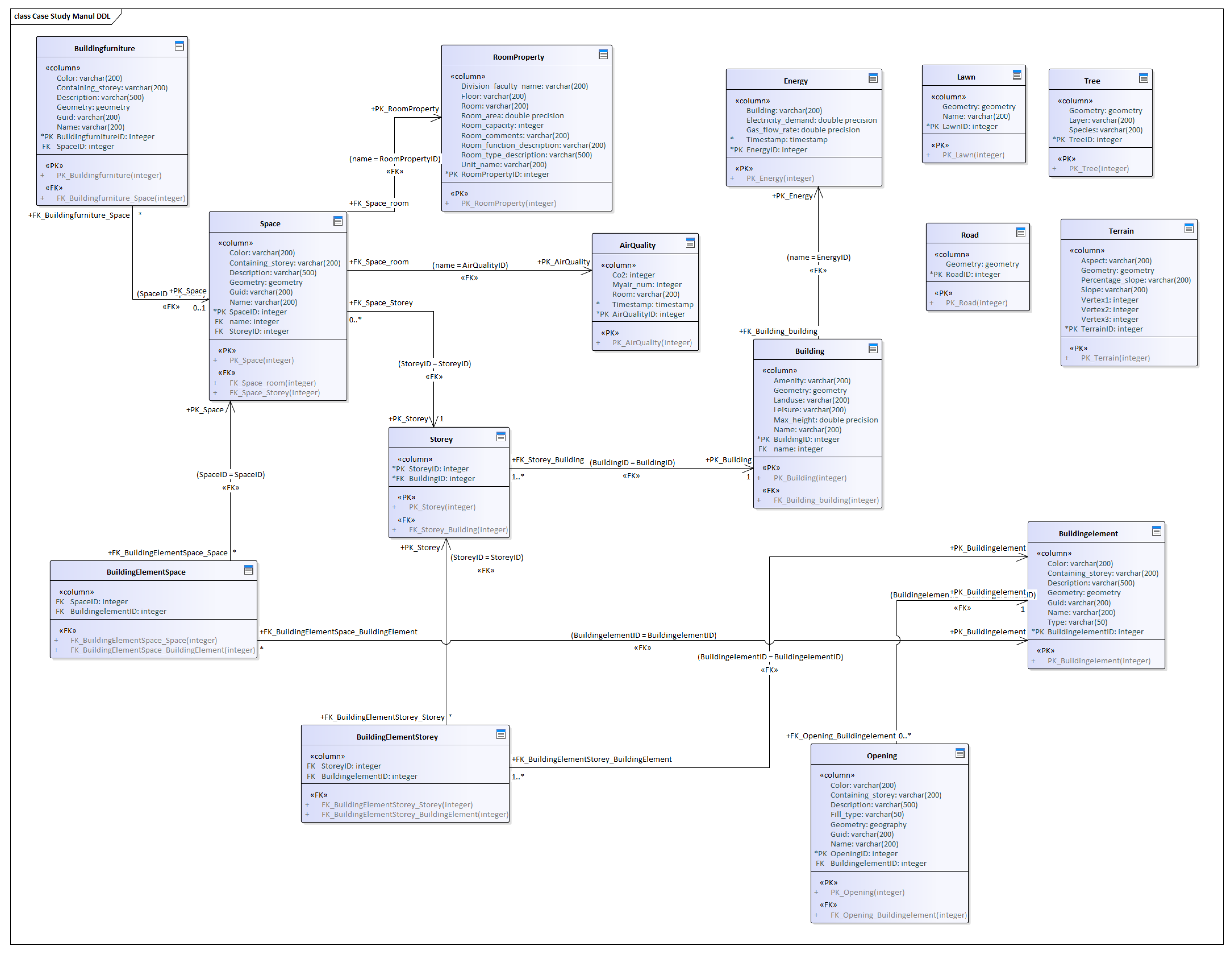
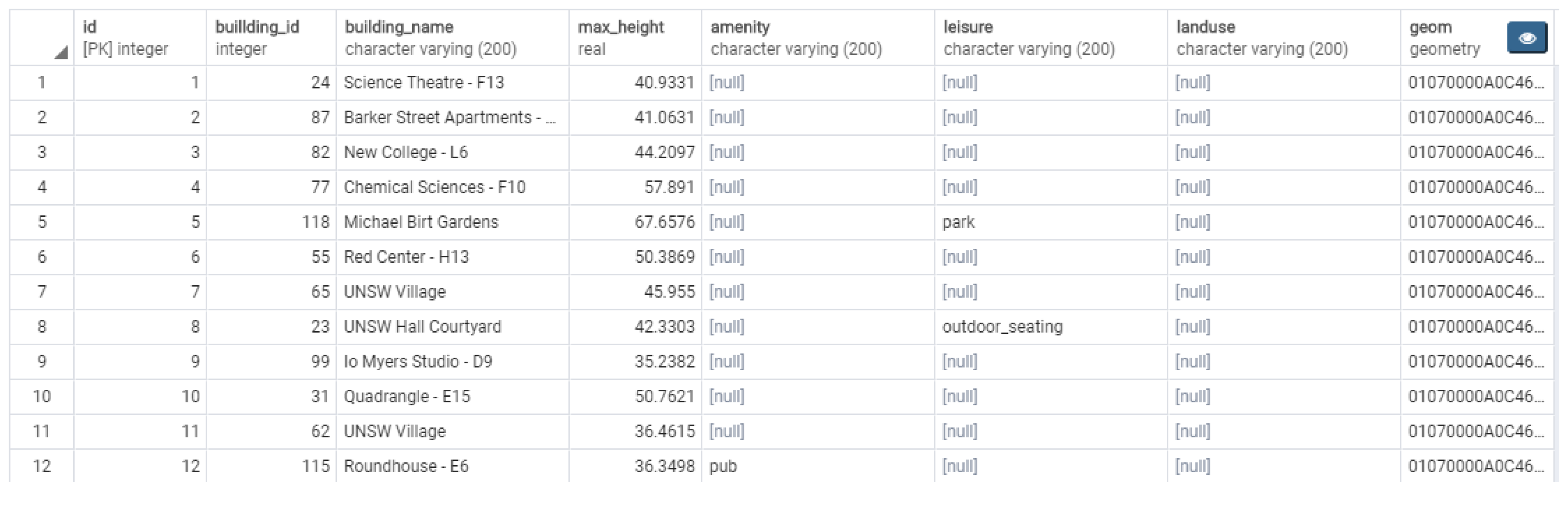
5.2. Relational Database Design

Employing spatial-RDBMS is the state-of-the-art solution to store and manage complex 3D building model, such as the open-source software PostgreSQL with PostGIS (https://postgis.net/) extension has extensive capabilities in handling 3D spatial data and supports all required geometry types and provide means for proper spatial indexing as well as for geometric and topological analysis. For example, volumes from the IFC models or the reconstructed from the 2D data can be represented as a POLYHEDRALSURFACE object. Each data type contains a spatial reference identifier (SRID) to describe the coordinate system as well. Using POLYHEDRALSURFACE over other possibilities (e.g., MULTIPOLYGON Z) allows using more PostGIS geometric functions with the SFCGAL extension (http://www.sfcgal.org/).
The UNSW campus model, described in Section 5.1 at the conceptual level, is realized by the tables shown in Figure 16. The pure CityGML class Terrain and its attributes specified in the UML (cf. Figure 15) diagram are directly mapped the TERRAIN table and its corresponding columns. In the same way, we realize class Road by the table ROAD. For the realization of vegetation objects, two separate tables are provided: LAWN and TREE. Due to different attribute list in two kinds of vegetation objects, we can ignore the abstract class _Vegetation in our realization. Same as vegetation, only one external reference object exists in our UML diagram, we just need to realize class Room Property into table ROOMPROPERTY with its attribute columns. In the same way, we map class Air Quality and Energy into table AIRQUALITY and ENERGY, respectively.
Building is the most complicated one. The class _Building is directly mapped the BUILDING table and its corresponding columns. The relation to the table ENERGY is established by the primary key name. The class Space and BuildingFurniture can be realized by table SPACE and BUILDINGFURNITURE directly, and all attribute specified in the UML diagram are reserved in their corresponding columns. Moreover, the relation to the table AIRQUALITY has arisen from the key name. The UML classes _Opening, Door and Window are realized by the single table OPENING. Door and window objects are distinguished by the attribute Fill_type (‘door’ or ‘window’). For the realization of building element objects, we can map all into one table BUILDINGELEMENT due to they have the same attribute list in our dataset. We distinguish different objects in _BuildingElement by the attribute type. We can also create three tables WALL, COVERING and BUIDLINGINSTALLATION to the different building element categories. In the following experimental part, we adopt the one BUILDINGELEMENT strategy to reduce the number of tables in our database.
Figure 17 illustrates the table BUILDING in the database. Along with the geometry, it includes the unique building IDs which can also be used for connecting Storey objects, the semantic information (e.g., leisure, land use, amenity) which is optional, the name which works as a foreign key to link Energy class.
Furthermore, GIS data describing a complete building often uses multiple geometries each depicts a component of a building. Therefore, we can also upward a relation BUILDING to store building ID and NAME and use BUILDINGPART to store semantic information of a building, respectively. A foreign key column building_id can be added in BUILDINGPART for representing the composition relationship as proposed mapping rule in Section 4. In the same way, to speed up the queries, we can assign building ID as a foreign key reference of Space and BuildingElement so that relation Storey can be omitted due to it works as bridge relation in current database design. Figure 16 illustrates the logical data model for our relational database design.

6. Discussion and Conclusions

In this paper, a relational 3D spatial-database solution for the management and analysis of PIM with multi-source data fusion was presented. We proposed a general conceptual and logical data model of building domain. To improve the performance of our integrated building model (IBM), we fused multi-source built-environment data to enhance semantic power and developed efficient mapping rules to simplify relational database design. The case study shows that our integrated building model can achieve a better understanding of the built environment and it will be a promising approach for future city or urban scale modeling work. Limitations of our approach are, (1) CityGML and IFC are not fully demonstrated and IBM should be made minor modifications for different real applications/scenarios; (2) the conversion or mapping among CityGML, IFC and IBM is a start point towards the integration of CityGML and IFC in concept. The identified limitations are also our future research directions. Except database access and query use cases in our conference paper [37] via customized datasets, in the future, we will deal with suitable multiple data sources with multiple level of details, and then create PIM under the specific application. Moreover, concerning how to analyse quality management and validity checking under multiple application scenarios is also interesting in our follow-up work.
There are several possible directions that can be explored for future works. First, how to enrich urban environment models for specific purposes or applications is interesting and promising. Second, integrating existing models (e.g., IFC model and CityGML model) is still a challenging work. For instance, two alternatives to implementation for integration can be discussed [38]. In the first alternative, the common geometric representations of all objects are identified and stored in separate tables. The thematic semantic tables would be linked to the geometric tables. In the second alternative the thematic semantic tables would integrate the geometries. Design and comparison of different integration implementations will be the next stage of our work.
In the current implementation we have used only the currently available datatypes of spatial DBMS. However, converting CSG, sweep and parametric geometries provided in IBM models results in unnecessary complex and large BRep. Two alternative directions for more compact storage can be investigated. One option will be organising such geometries as BLOB in the database. The second option is to introduce user-defined data types, which can maintain mathematically defined geometry [39].

Author Contributions

Conceptualization, W.L.; Data curation, W.L., A.A.D., M.A. and J.Y.; Formal analysis, W.L.; Funding acquisition, S.Z.; Investigation, W.L. and S.Z.; Methodology, W.L.; Software, W.L.; Supervision, S.Z.; Visualization, W.L.; Writing—original draft, W.L.; Writing—review & editing, S.Z., A.A.D., M.A. and J.Y. All authors have read and agreed to the published version of the manuscript.

Funding

Case study is supported by CRC for Low Carbon Living Ltd supported by the Cooperative Research Centers program (No. RP2011u1).

Conflicts of Interest

The authors declare no conflict of interest.

Abbreviations

The following abbreviations are used in this manuscript:
BIMBuilding Information Modeling
CADComputer Aided Design
DBMSDatabase Management System
GISGeographic Information System
GMLGraphics Mark-up Language
IFCIndustry Foundation Classes
ISOInternational Standards Organization
OGCOpen Geospatial Consortium
PIMPrecinct Information Modeling
SQLStructured Query Language

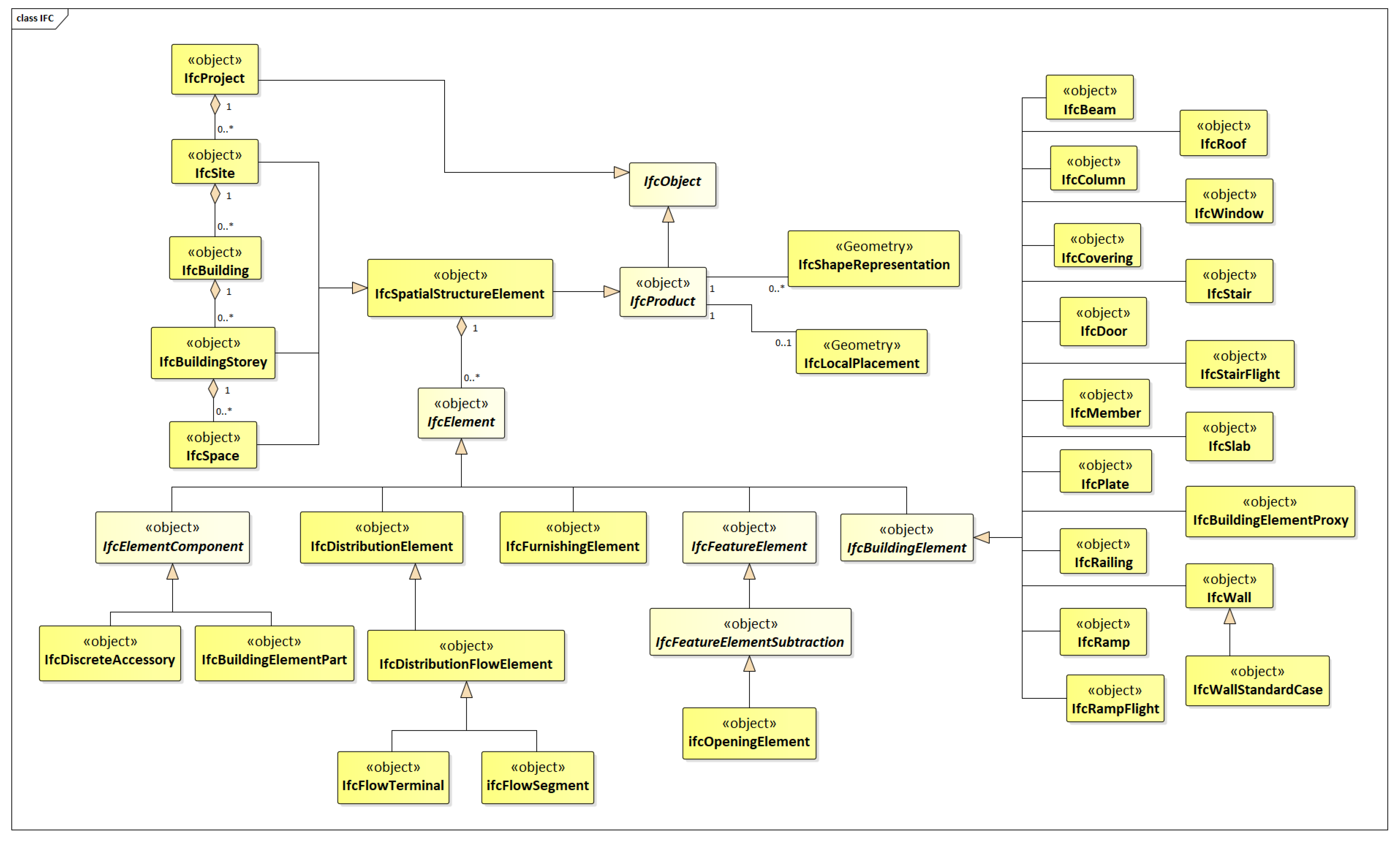
Appendix A. IFC Building Model

From IFC4 standards we identify important concepts for building model (Figure A1).
Figure A1. IFC building model.
Ijgi 09 00063 g0a1

Appendix B. CityGML Building Model

From CityGML2.0 standards we identify important concepts for building model (Figure A2).
Figure A2. CityGML building model.
Ijgi 09 00063 g0a2

References

  1. Biljecki, F.; Stoter, J.; Ledoux, H.; Zlatanova, S.; Çöltekin, A. Applications of 3D city models: State of the art review. ISPRS Int. J. Geo-Inf. 2015, 4, 2842–2889. [Google Scholar] [CrossRef] [Green Version]
  2. Murata, M. 3D-GIS application for urban planning based on 3D city model. In Proceedings of the 24th Annual ESRI International User Conference, San Diego, CA, USA, 9–13 August 2004. [Google Scholar]
  3. Shiode, N. 3D urban models: Recent developments in the digital modelling of urban environments in three-dimensions. GeoJournal 2000, 52, 263–269. [Google Scholar] [CrossRef]
  4. Fadli, F.; Kutty, N.; Wang, Z.; Zlatanova, S.; Mahdjoubi, L.; Boguslawski, P.; Zverovich, V. Extending indoor open street mapping environments to navigable 3D CityGML building models: Emergency response assessment. Int. Arch. Photogramm. Remote Sens. Spat. Inf. Sci. 2018, 42, 161–168. [Google Scholar] [CrossRef] [Green Version]
  5. Walenciak, G.; Stollberg, B.; Neubauer, S.; Zipf, A. Extending spatial data infrastructures 3D by geoprocessing functionality-3D simulations in disaster management and environmental research. In Proceedings of the 2009 International Conference on Advanced Geographic Information Systems & Web Services, Cancun, Mexico, 1–7 February 2009; pp. 40–44. [Google Scholar]
  6. Krüger, A.; Kolbe, T. Building analysis for urban energy planning using key indicators on virtual 3D city models—The energy atlas of Berlin. Int. Arch. Photogramm. Remote Sens. Spat. Inf. Sci. 2012, 39, 145–150. [Google Scholar] [CrossRef] [Green Version]
  7. Breunig, M.; Zlatanova, S. 3D geo-database research: Retrospective and future directions. Comput. Geosci. 2011, 37, 791–803. [Google Scholar] [CrossRef]
  8. Lo, C.P.; Yeung, A.K. Concepts and Techniques of Geographic Information Systems; Prentice Hall: Upper Saddle River, NJ, USA, 2002. [Google Scholar]
  9. Azhar, S.; Khalfan, M.; Maqsood, T. Building information modelling (BIM): Now and beyond. Construct. Econ. Build. 2012, 12, 15–28. [Google Scholar] [CrossRef] [Green Version]
  10. Newton, P.; Plume, J.; Marchant, D.; Mitchell, J.; Ngo, T. Precinct information modelling: a new digital platform for integrated design, assessment and management of the built environment. In Integrating Information in Built Environments; Routledge: London, UK, 2017; pp. 111–132. [Google Scholar]
  11. Cai, G. Contextualization of geospatial database semantics for human–GIS interaction. Geoinformatica 2007, 11, 217–237. [Google Scholar] [CrossRef]
  12. Gröger, G.; Kolbe, T.; Nagel, C.; Häfele, K. OGC City Geography Markup Language (CityGML) Encoding Standard; Open Geospatial Consortium: Wayland, MA, USA, 2012. [Google Scholar]
  13. ISO. Industry Foundation Classes (IFC) for Data Sharing in The Construction and Facility Management Industries; International Organization for Standardization: Geneva, Switzerland, 2013. [Google Scholar]
  14. Güting, R.H. An introduction to spatial database systems. VLDB J. Int. J. Very Large Data Bases 1994, 3, 357–399. [Google Scholar] [CrossRef]
  15. Tolmer, C.E.; Castaing, C.; Diab, Y.; Morand, D. CityGML and IFC: Going further than LOD. In Proceedings of the 2013 Digital Heritage International Congress (DigitalHeritage), Marseille, France, 28 October–1 November 2013; Volume 1, pp. 645–648. [Google Scholar]
  16. Deng, Y.; Cheng, J.C.; Anumba, C. Mapping between BIM and 3D GIS in different levels of detail using schema mediation and instance comparison. Autom. Construct. 2016, 67, 1–21. [Google Scholar] [CrossRef]
  17. Liu, X.; Wang, X.; Wright, G.; Cheng, J.; Li, X.; Liu, R. A state-of-the-art review on the integration of Building Information Modeling (BIM) and Geographic Information System (GIS). ISPRS Int. J. Geo-Inf. 2017, 6, 53. [Google Scholar] [CrossRef] [Green Version]
  18. Ghamisi, P.; Rasti, B.; Yokoya, N.; Wang, Q.; Hofle, B.; Bruzzone, L.; Bovolo, F.; Chi, M.; Anders, K.; Gloaguen, R.; et al. Multisource and Multitemporal Data Fusion in Remote Sensing. arXiv 2018, arXiv:1812.08287. [Google Scholar]
  19. Zhu, Q.; Hu, M.; Zhang, Y.; Du, Z. Research and practice in three-dimensional city modeling. Geo-Spat. Inf. Sci. 2009, 12, 18–24. [Google Scholar] [CrossRef]
  20. Billen, R.; Cutting-Decelle, A.F.; Marina, O.; De Almeida, J.P.; Caglioni, M.; Falquet, G.; Leduc, T.; Metral, C.; Moreau, G.; Perret, J.; et al. 3D City Models and Urban Information: Current Issues and Perspectives-European COST Action TU0801; EDP Sciences: Les Ulis, France, 2014. [Google Scholar]
  21. Nakashima, H.; Aghajan, H.; Augusto, J.C. Handbook of Ambient Intelligence and Smart Environments; Springer Science & Business Media: Cham, Switzerland, 2009. [Google Scholar]
  22. Zhang, J.; Seet, B.C.; Lie, T. Building information modelling for smart built environments. Buildings 2015, 5, 100–115. [Google Scholar] [CrossRef] [Green Version]
  23. Bleiholder, J.; Naumann, F. Data fusion. ACM Comput. Surv. (CSUR) 2009, 41, 1. [Google Scholar] [CrossRef]
  24. Dong, J.; Zhuang, D.; Huang, Y.; Fu, J. Advances in multi-sensor data fusion: Algorithms and applications. Sensors 2009, 9, 7771–7784. [Google Scholar] [CrossRef] [Green Version]
  25. Rigaux, P.; Scholl, M.; Voisard, A. Spatial Databases: With Application to GIS; Elsevier: Amsterdam, The Netherlands, 2001. [Google Scholar]
  26. Zlatanova, S. 3D geometries in spatial DBMS. In Innovations in 3D Geo Information Systems; Springer: Berlin/Heidelberg, Germany, 2006; pp. 1–14. [Google Scholar]
  27. Wang, X.; Love, P.E.; Kim, M.J.; Park, C.S.; Sing, C.P.; Hou, L. A conceptual framework for integrating building information modeling with augmented reality. Autom. Construct. 2013, 34, 37–44. [Google Scholar] [CrossRef]
  28. Nagel, C.; Stadler, A.; Kolbe, T.H. Conceptual requirements for the automatic reconstruction of building information models from uninterpreted 3D models. In Proceedings of the Academic Track of the Geoweb 2009-3D Cityscapes Conference, Vancouver, BC, Canada, 27–31 July 2009. [Google Scholar]
  29. El-Mekawy, M.; Östman, A.; Hijazi, I. A unified building model for 3D urban GIS. ISPRS Int. J. Geo-Inf. 2012, 1, 120–145. [Google Scholar] [CrossRef] [Green Version]
  30. Cheng, J.C.; Deng, Y.; Anumba, C. Mapping BIM schema and 3D GIS schema semi-automatically utilizing linguistic and text mining techniques. J. Inf. Technol. Construct. 2015, 20, 193–212. [Google Scholar]
  31. Kang, T.W.; Hong, C.H. A study on software architecture for effective BIM/GIS-based facility management data integration. Autom. Construct. 2015, 54, 25–38. [Google Scholar] [CrossRef]
  32. Agoub, A.; Kunde, F.; Kada, M. Potential of graph databases in representing and enriching standardized Geodata. Tagungsband der 2016, 36, 1–9. [Google Scholar]
  33. Stadler, A.; Nagel, C.; König, G.; Kolbe, T.H. Making interoperability persistent: A 3D geo database based on CityGML. In 3D Geo-Information Sciences; Springer: Berlin/Heidelberg, Germany, 2009; pp. 175–192. [Google Scholar]
  34. Robert McNeel & Associates. Rhinoceros: 3D Computer Graphics and Computer-Aided Design Application). 2019. Available online: https://www.rhino3d.com/ (accessed on 27 May 2019).
  35. IFC++. IFC++: Open Source IFC Implementation for C++). 2019. Available online: http://ifcquery.com/ (accessed on 27 May 2019).
  36. The CGAL Project. CGAL User and Reference Manual, 4th ed.; CGAL Editorial Board: Tel-Aviv, Israel, 2019. [Google Scholar]
  37. Li, W.; Zlatanova, S.; Yan, J.; Diakite, A.; Aleksandrov, M. A Geo-Database Solution for the Management and Analysis of Building Model with Multi-Source Data Fusion. Int. Arch. Photogramm. Remote Sens. Spat. Inf. Sci. 2019, 42, 55–63. [Google Scholar] [CrossRef] [Green Version]
  38. Emgård, L.; Zlatanova, S. Implementation alternatives for an integrated 3D Information Model. In Advances in 3D Geoinformation Systems; Springer: Berlin/Heidelberg, Germany, 2008; pp. 313–329. [Google Scholar]
  39. Zlatanova, S.; Pu, S.; Bronsvoort, W. Freeform curves and surfaces in DBMS-a step forward in spatial data integration. In Proceedings of the ISPRS Commission IV Symposium on ‘Geospatial Databases for Sustainable Development, Goa, India, 27–30 September 2006; pp. 27–30. [Google Scholar]
Figure 1. Spatial information platforms for the built environment (Source: ref. [10]).
Ijgi 09 00063 g001
Figure 2. Paradigm of the data fusion.
Ijgi 09 00063 g002
Figure 3. An integrated spatial DBMS.
Ijgi 09 00063 g003
Figure 4. The process of data modeling.
Ijgi 09 00063 g004
Figure 5. UML diagram of thematic top-level classes.
Ijgi 09 00063 g005
Figure 6. UML diagram of integrated building model (IBM).
Ijgi 09 00063 g006
Figure 7. Classification of Openings (Source: ref. [12]).
Ijgi 09 00063 g007
Figure 8. Examples of the classification of _BoundarySurfaces in CityGML of the outer building shell (Source: ref. [12]).
Ijgi 09 00063 g008
Figure 9. UML diagram of sensor model.
Ijgi 09 00063 g009
Figure 10. UML diagram of land use model.
Ijgi 09 00063 g010
Figure 11. UML diagram of city furniture model.
Ijgi 09 00063 g011
Figure 12. UML diagram of transportation model.
Ijgi 09 00063 g012
Figure 13. UML diagram of vegetation model.
Ijgi 09 00063 g013
Figure 14. UML diagram of terrain model.
Ijgi 09 00063 g014
Figure 15. UML diagram for integrated UNSW campus model.
Ijgi 09 00063 g015
Figure 16. Logical data model for our relational database design.
Ijgi 09 00063 g016
Figure 17. Example of a table stored in PostgreSQL to store building objects.
Ijgi 09 00063 g017
Table 1. Transformation rules from IFC & CityGML to IBM.
LODMapping Rule
LOD1_AbstractBuilding_Building
LOD2RoofSurfaceRoof
OuterCeilingSurfaceOuterCeiling
WallSurfaceExteriorWall
GroundSurfaceGround
FloorSurfaceOuterFloor
_BoundarySurface_BoundarySurface
BuildingInstallation_BuildingInstallation
LOD3IfcBuildingElement_BuildingElement
[_Opening,IfcOpeningElement] ⇒ _Opening
[Window,IfcWindow] ⇒ Window
[Door,IfcDoor] ⇒ Door
IfcWallExteriorWall
IfcCurtainWallCurtainWall
IfcRoofRoof
IfcSlabGround
[IfcWall,IfcRoof,IfcSlab] ⇒ _BoundarySurface
[IfcBuildingStorey, _BoundarySurface] ⇒ BuildingStorey
LOD4[InteriorWallSurface,IfcWall] ⇒ InteriorWall
[CeilingSurface,IfcSlab] ⇒ Ceiling
[FloorSurface,IfcSlab] ⇒ Floor
[Room, _BoundarySurface] ⇒ Space
BuildingFurnitureBuildingFurniture
IntBuildingInstallationBuildingInstallation
Table 2. Data type mapping.
UMLPostgreSQL/PostGIS
String, anyURIVARCHAR/TEXT
IntINT/NUMERIC
DoubleFLOAT/REAL/NUMERIC
BooleanBOOLEAN
DateDATE/TIMESTAMP
PcpatchPCPATCH
GML GeometryGEOMETRY

