1. Introduction
Since fuels obtained from crude oil (as a non-renewable source) increase the amount of carbon dioxide in the atmosphere when burned, it is planned to use alternative energy sources worldwide. Moreover, one of the trends in the development of the up-to-date fuel industry is tightening requirements for fuels, which must be high-octane and, simultaneously, have improved environmental characteristics [
1]. In most developed countries, governments stimulate the use of renewable energies and resources with the following primary goals: to secure access to energy, to mitigate climate changes, to develop/maintain agricultural activities, and to ensure food safety [
2,
3]. One way to solve this problem, considering in many countries, is the wide use of biofuels as a mixture of motor types of gasoline with oxygenates, particularly bioethanol [
4].
According to “OECD-FAO Agricultural Outlook 2020–2029”, world bioethanol production is projected to grow from 122 billion liters (over the base period) to 143 billion liters by 2028. Simultaneously, global biodiesel production will be reached by 44 billion liters [
5]. Notably, leading biofuel producers are the USA, Brazil, Indonesia, Germany, China, Thailand, and Spain [
6].
Additionally, according to forecasts of the International Energy Agency (IEA), in 2050, the production of biofuels will reach 760 million tons of oil equivalent. More detailed prospects are described in IEA’s “Technology Roadmap—Biofuels for Transport” [
7,
8]. During the next five years, the production of biofuels is expected to increase by 15%, reaching 165 billion liters. It is predicted that by 2023, biofuels will account for about 90% of the renewables used in transport [
9]. Before the COVID-19 pandemic, global bioethanol production was expected to increase to 130 billion L by 2024 [
10]. A contraction of 13% in 2020 is now expected for biofuels due to pandemic transport [
9], but growth can be expected to resume once the pandemic abates. Fuel ethanol accounts for about two-thirds of biofuel production growth, whereas biodiesel and hydrotreated vegetable oil account for the rest. The countries in Asia account for most of the growth in biofuel output during the next five years. China, India, and member states of the Association of Southeast Asian Nations represent half of the worldwide expansion in biofuel production. Latin America is responsible for an extra 45% of that growth, especially Brazil [
11].
Comprehensively considering the problem of implementing biofuel technologies [
12], it should be noted that this problem is straightforwardly related to the fields of economics, ecology, science and technology, food, and energy sources. In this regard, the feasibility of using biofuels as a primary energy source depends on its energy efficiency.
Based on data [
13], after considering energy balances, the energy profitability of biofuels is determined, which in the case of bioethanol production from raw materials is as follows: corn—1.5, sugar beet—2, wheat—2–4, sugar cane—2–8, and cellulose—2–36.
Notably, rape is also a common raw material for liquid biofuels. However, it is used mainly in biodiesel production. The article deals with the production of light biofuel (bioethanol) from second-generation raw material sources (i.e., lignocellulose compounds). Therefore, based on the literature review, straw was used as a cellulose-containing raw material for bioethanol production. More detailed information about the raw material is presented below in
Table 1.
It is well-known that the primary disadvantage of first-generation bioethanol production is the reduction of crops from cereals, sugar, and oilseeds needed for the food industry. This fact causes the transition to second-generation bioethanol production technologies based on lignocellulose biomass obtained from specialized high-tech crops (e.g., Jatropha, Mánihot, and Miscánthus) or from non-food agricultural waste (e.g., sunflower seed pomace, straw, sugar cane pomace, and sawdust). In this case, the main technological stages are the collection and the pretreatment of raw materials (biomass), hydrolysis and fermentation of cellulose and lignin, the distillation of ethanol, dehydration and separation of lignin, and burning of lignin at thermal power plants for the needs of primary production [
14]. Thus, according to the second-generation technology, particular attention should be paid to energy efficiency and energy saving in the production of fuel bioethanol from lignocellulose raw materials.
Recent economic calculations for obtaining bioethanol from grain and woods have shown the following. In the cost of ethanol from grain, costs for raw materials and fermentation are about 62 to 70%. In the hydrolysis production of ethanol from wood waste, the cost of raw materials is about 12%. The high costs in the first are explained by the low consumption of heat and energy resources and high preparatory costs for fermentation (about 5% of the general cost). In the second case, the costs are heat and energy resources (about 40%) and fixed costs (about 40%) [
15].
Ethanol production is usually carried out in three stages: obtaining a solution containing the enzyme sugars, fermented conversion of sugars into ethanol, and the consequent separation and purification (usually by distillation, rectification, and dehydration). The following papers deal with different technological processes of second-generation bioethanol production. Notably, in the research work [
16], the pretreatment of stillage by sulfuric acid at temperatures above 130 °C was considered. It has been demonstrated that the final concentration of ethanol can reach 90 g/l. When diluting molasses using acid-treated corn stillage, the process yield was more than 94% of the theoretical one. In the future, this data can be used as input for the subsequent mathematical modeling. However, such technology is associated with the inevitable depletion of ethanol obtained from raw materials.
Besides, in the article [
17], calculations of separate technological processes using the nonlinear regression procedures were carried out. As a result of computer simulation using “ASPEN PLUS” and nonlinear regression methods, an optimization model was developed in “LINGO” and solved for an optimal processing mode. The research results showed that the best treatment includes corn straw as biomass feedstock and uses an “AFEX” pretreatment step. The results also showed that the optimum plant capacity for other configurations is typical of 730,000 to 1,460,000 tons/year. Notably, chemical sensitivity analysis showed that the pretreatment process leads to significant fluctuations in the minimum price of ethanol due to large fluctuations in the cost of ammonia. Due to the results mentioned above, the problem of ensuring optimal conditions for the production of bioethanol at significantly lower productivity (e.g., about 27,000 tons/year) is of particular interest.
In the research work [
18], economic and environmental analysis was carried out to simulate particular technological processes of hydrolysis and fermentation, considering the different stages of integration between units of first and second generations. The results showed that an integrated production of first-generation and second-generation ethanol from sugarcane leads to better economic results than a stand-alone plant. This is especially interesting considering the advanced technologies of hydrolysis and pentose fermentation. The rectification section from the first-generation ethanol production can be used further in the second-generation bioethanol technology.
Moreover, particular technological schemes to produce bioethanol from biomass are presented in [
19], and material balances are provided. However, energy consumption is not evaluated. Other authors describe the technology to produce bioethanol from wood, indicating the costs of cellulose hydrolysis and ethanol fermentation. However, the costs for distillation, rectification, and dehydration processes are not indicated [
20].
The work aims to study various technological modes at the rectification unit to produce fuel ethanol from lignocellulosic biomass, analyzing energy consumption and the quality of bioethanol. In this regard, the primary goals are to solve scientific and applied problems of technological (e.g., temperature) and design (number of columns) optimizations to obtain boundaries of energy consumption to ensure the quality of bioethanol sufficient for a consumer. Finally, it is advisable to evaluate heat energy to obtain bioethanol of sufficient concentration.
2. Materials and Methods
The initial data for modeling were taken from the enterprises designed by JSC “Biochemtex” (Tortona, Italy) and the composition of the initial product—from the research [
21]. The analysis has been carried out according to the fuel quality standards [
22,
23].
For studying the rectification process and providing the technological parameters in bioethanol production, numerical modeling is applied using tools for simulating chemical technological processes [
24].
The simulation model is designed from different modules that allow us to simulate efficiently and accurately technological processes in all the units of technological equipment at the rectification plant.
For modeling processes in brew and epuration columns, the strict rectification and absorption module is used. It allows us to simulate the separation process for a multicomponent mixture on each rectification plate. For accurate modeling of the reflux condenser for both columns, condenser modules of the brew and epuration columns are replaced by sequentially interconnected heat exchanger and phase separator calculation modules. The alcohol column is modeled using the shortcut model of the “ChemCAD v.5.1.3” software. The corresponding module is based on the Fenske-Underwood-Gilliland method.
For simulating the process, the activity coefficient UNof the IFAC model of phase equilibrium [
25,
26] is used as a system for the prediction of non-electrolyte activity in non-ideal mixtures. Software developers recommend such an approach for modeling mass transfer processes in this type of process equipment and the composition of feed streams. The choice of the equilibrium model is justified by its scope and boundary conditions for the model of phase and thermodynamic equilibrium [
27]. The proposed model fully meets these requirements.
The boundary conditions for modeling have been selected from the conditions of the maximum range of stable functioning of the mathematical model of the technological process. Particularly, the lower range of optimization modeling has been determined as the minimum possible energy consumption for the rectification process. At these values, the mathematical model of the process can function without critical errors in the material or heat balance.
Determination in a similar way to the upper limit of mathematical modeling for the technological process of ethanol distillation is not rational because an increase in energy consumption for the technological process leads to stable results in a wide range of parameters. Therefore, the upper limit of mathematical modeling has been chosen based on the permissible properties of the output ethanol flow based on the required minimum permissible ethanol concentration in the distillate.
The simulation aims to determine the effect of changing the technological parameters on the quality indicators of the final product and energy consumptions.
The amount of raw material is the same for each option. The consumptions of water vapor entering the brew, epuration, and alcohol columns are varied. The energy consumption for the separation process in each column is defined as the thermal energy required to produce the final bioethanol of 5707 tons/year.
The primary technological data of the process are indicated in
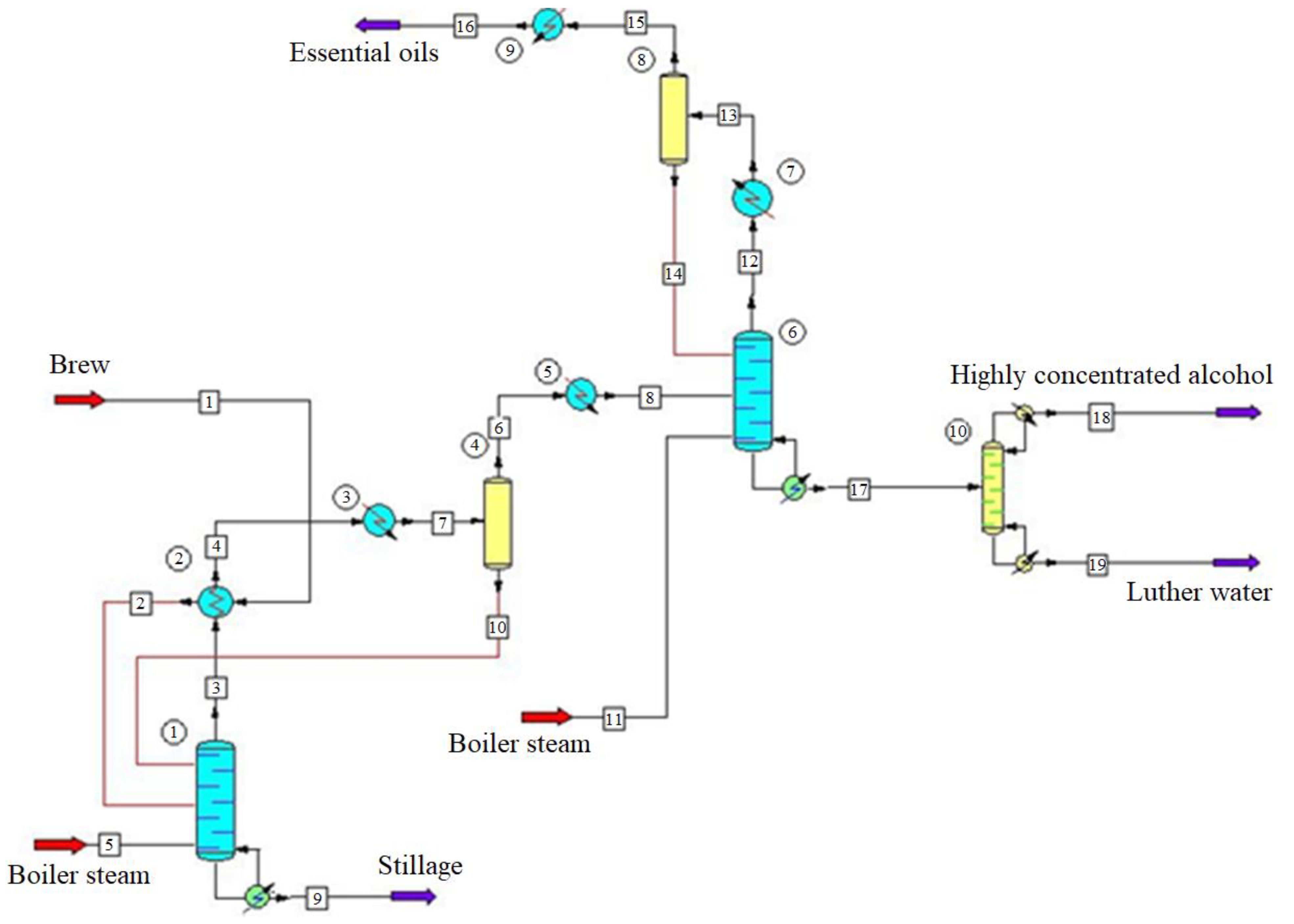
Table 1. The corresponding design scheme is presented in
Figure 1.
Brew with a concentration of 15% (mass, bioethanol) with a temperature of 22 °C is transferred from the brew unit to heater 2 (heating temperature is in a range of 75 to 80 °C). Next, the mixture is fed to brew column 1 on the 14th plate and immediately cooled on the 2nd flow by alcohol vapors. At the exit of the upper part of column 1, vapors reach a concentration of 60% (mass) and enter condenser 3 for cooling and condensing. After, the raw alcohol enters distributor 4, where it is divided into two flows. The first one returns to the brew column as phlegm. The second flow is fed on the 12th plate of the epuration column 6. Vapors are removed from the epuration column (after condensation in apparatus 7) divided into two flows in the distributor 8. The first flow returns as phlegm to the first plate of the epuration column 6, where irrigation occurs; the second one is removed. From the lower part of the epuration column 6, the epurate is removed and enters the alcohol column 10 on the 7th plate. At this stage, the concentration of the epurate is 50% (mass). Impurities are removed with Luther water, which contains esters and aldehydes.
Luther water is removed from the alcohol column 10. Vapors of bioethanol with a concentration of 96% (mass) are transferred to the reflux condenser. After, one part of the bioethanol is returned to the alcohol column as phlegm. The second one is removed as a final product.
In global practice, both absolute and watered alcohol are components of motor fuel. In Sweden, two brands of bioethanol are used for biofuels [
22] with the following characteristics: 95.0% and 99.5%. In the USA, according to international standard “ASTM D4806-21—Standard Specification for Denatured Fuel Ethanol for Blending with Gasolines for Use as Automotive Spark-Ignition Engine Fuel”, the characteristics for denatured fuel ethanol is 92.1%. Additionally, Brazilian fuel ethanol has two brands [
23] with the following technical characteristics: 99.3% and 92.6 to 93.8%.
3. Results
Bioethanol production from lignocellulosic biomass requires energy costs to obtain process steam, electricity, and cooling water. The primary energy used during the process is the thermal energy of steam.
The simulation is conducted in stationary mode. The calculation results (mass flow rate, temperature, and fractional composition) of the output flows for brew, epuration, and alcohol columns are summarized in
Table 2,
Table 3 and
Table 4, respectively.
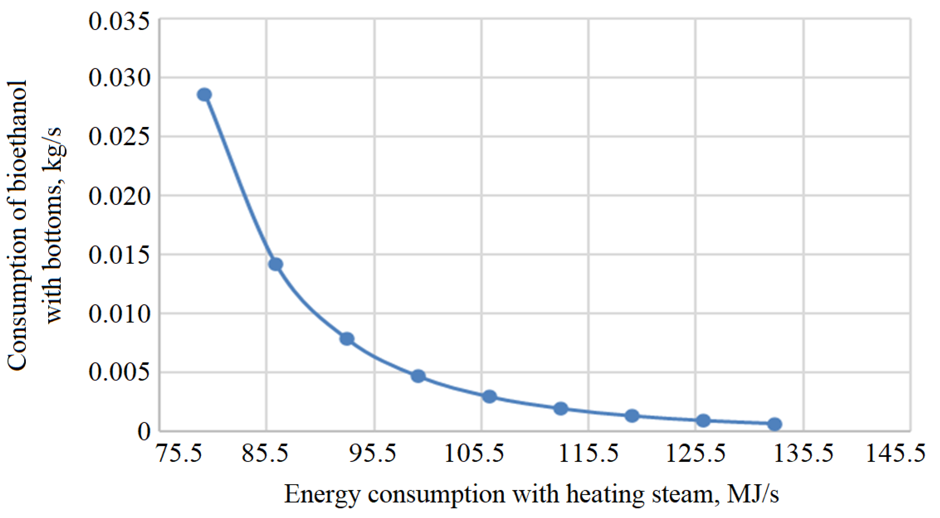
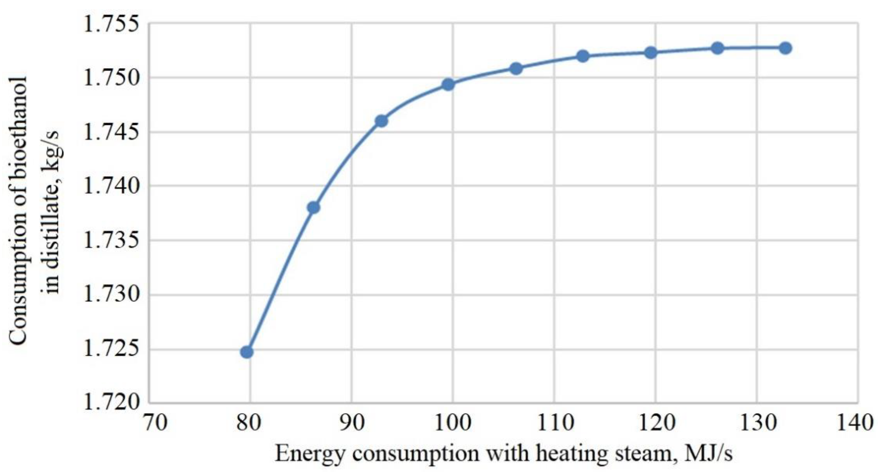
For ensuring the proper operation of the brew column, steam is fed to the lower part. For increasing the efficiency of the column, steam consumption varies in a range of 6 to 10 kg/s. In this case, 50% of bioethanol in the distillate meets the technological standards.
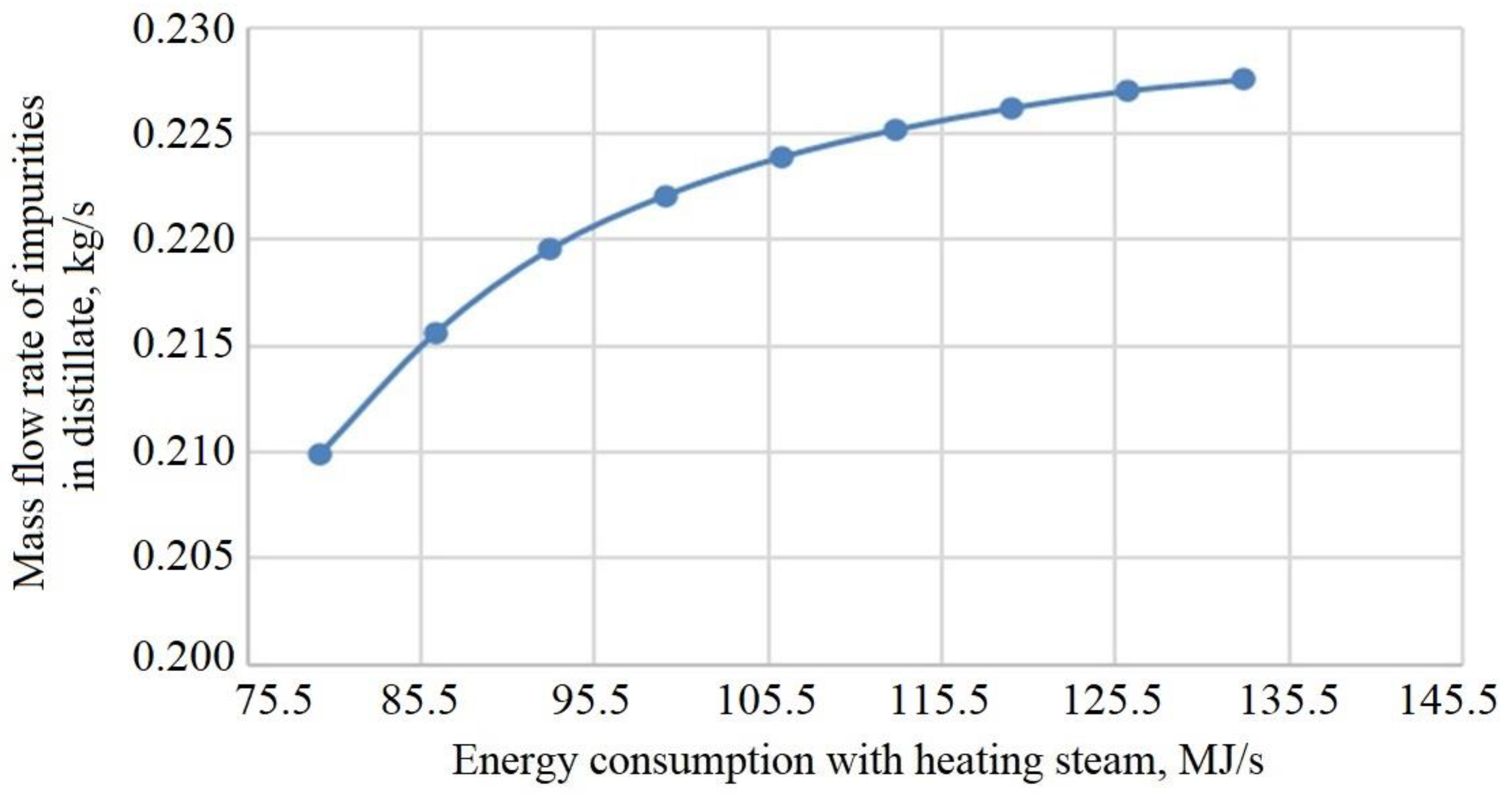
Figure 2 shows that an increase in energy consumption with heating steam allows us to reduce bioethanol losses with bottoms, increasing the content of bioethanol in distillate (
Figure 3). However, an increase in energy consumption with heating steam increases impurities in distillate (
Figure 4).
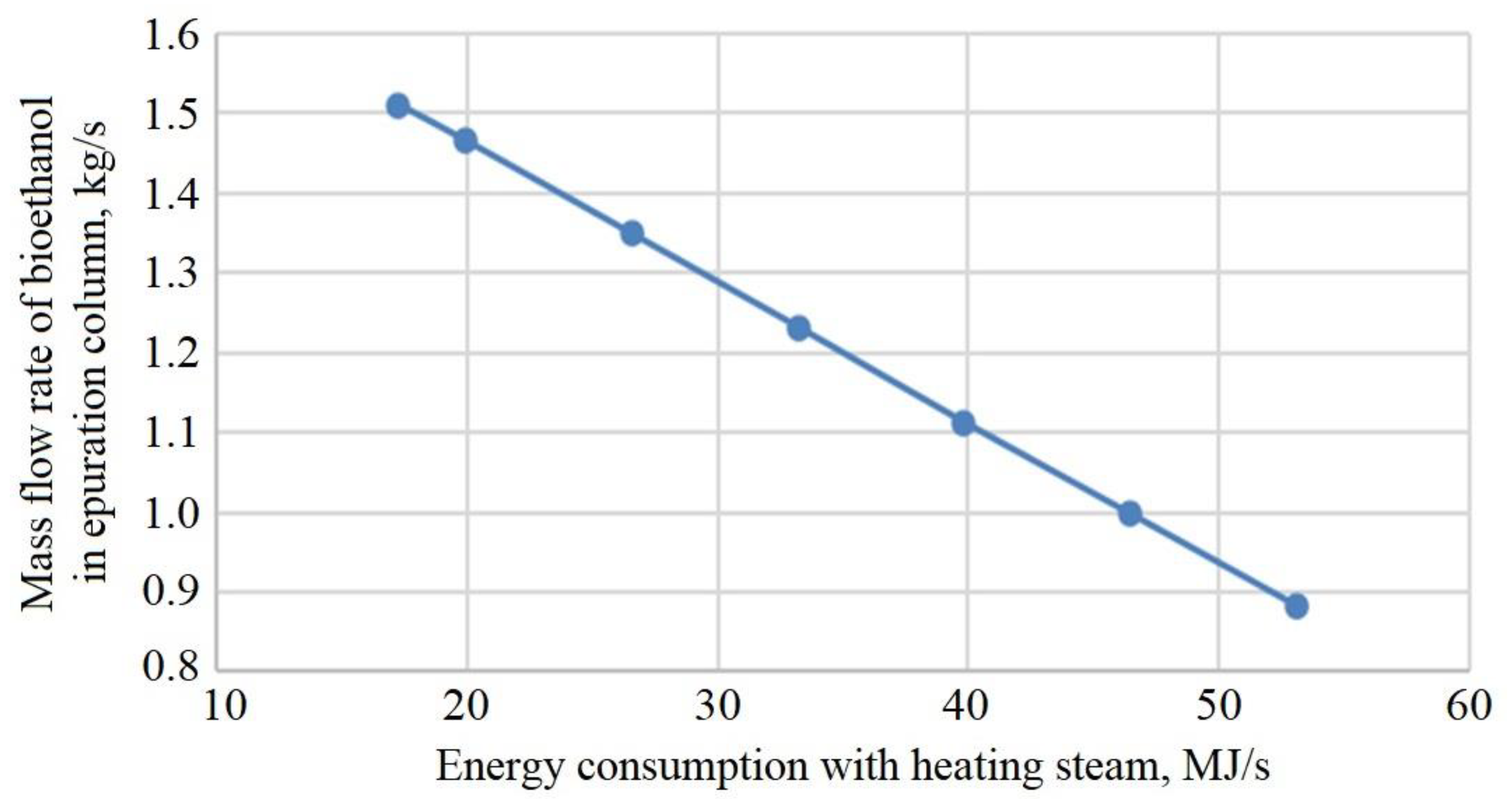
For ensuring the operation of the epuration column, steam is supplied in the lower part. The distillate obtained in the brew column is the raw material. The steam consumption varies in a range of 1.3 to 4.0 kg/s, equivalent to 17 to 56 MJ/s. This data allows us to rationalize the column, ensuring the maximum mass fraction of 81% of bioethanol in the distillate, which meets technological standards.
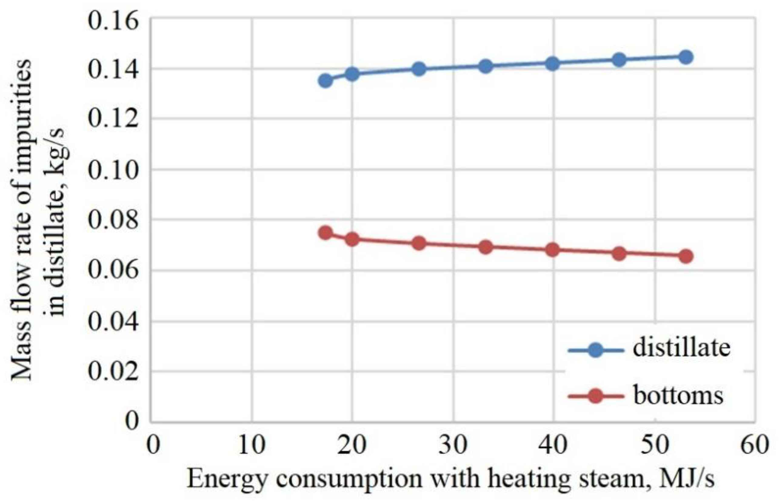
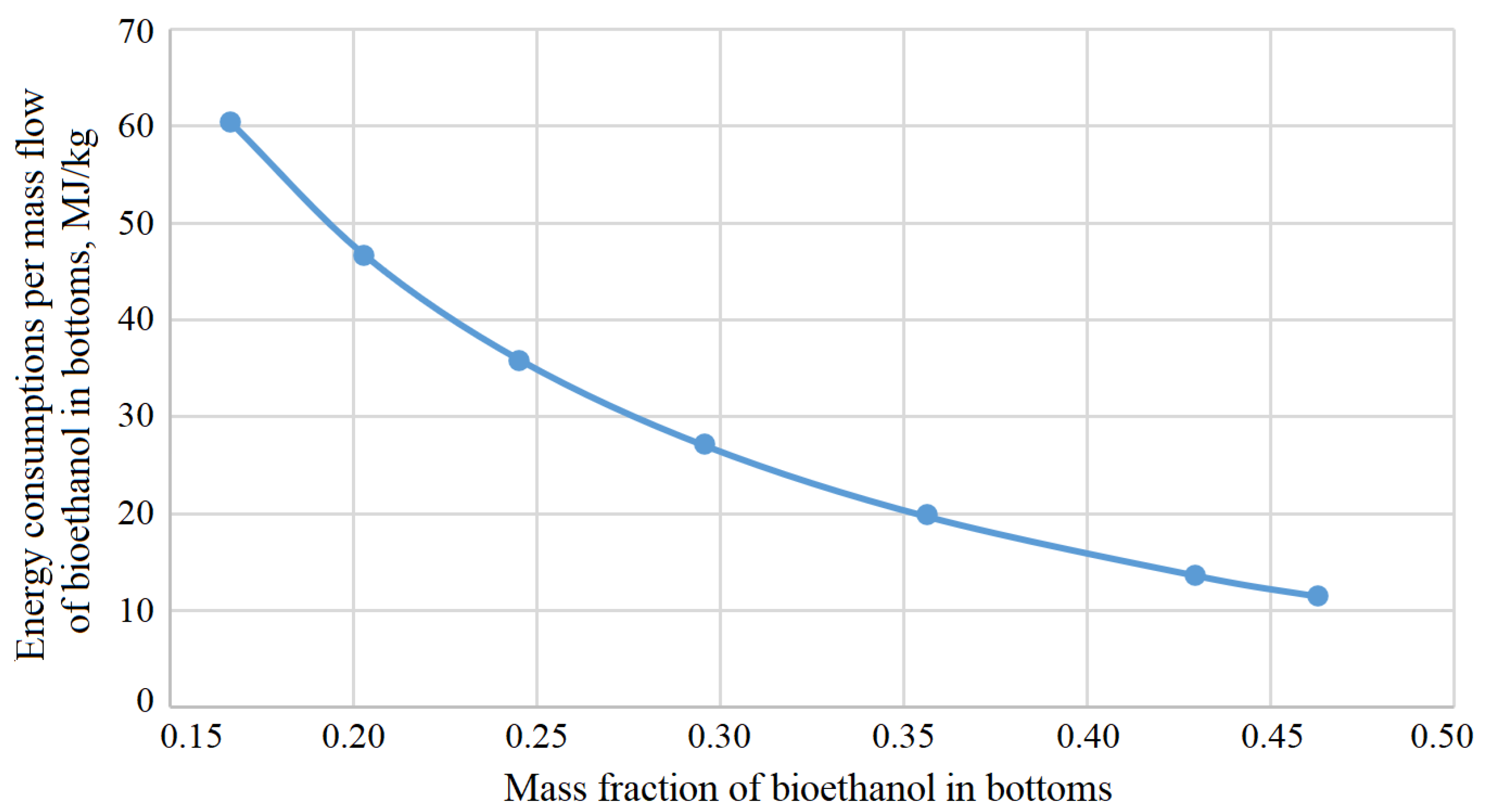
Figure 5 shows that with increasing energy consumption with heating steam, bioethanol in the bottoms decreases. The mass flow rate impurities in the bottoms also decrease. Besides, a decrease in impurities in distillate improves the quality of essential oil (
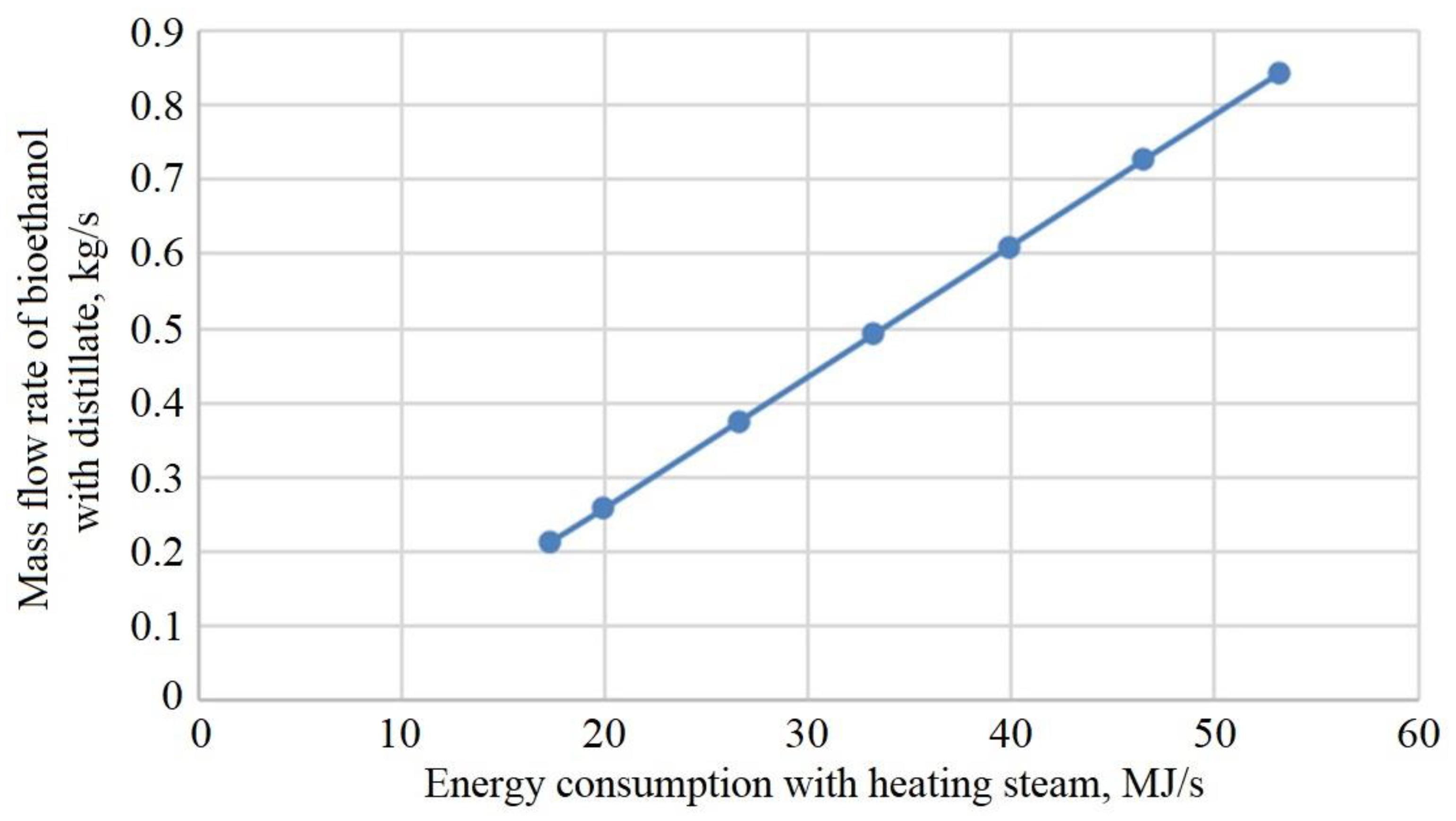
Figure 6). If impurities (essential oils) are left in the bottoms, then in the alcohol column, they will be released with Luther water. Moreover, an increase in energy consumption with heating steam reduces bioethanol in the distillate (
Figure 7).
In the bottom part of the alcohol column, a boiler is used to heat and evaporate the bottoms. For ensuring the operation of the alcohol column, steam is fed into the boiler. The distillate obtained in the epuration columns is the raw material. Calculation results summarized in
Table 4 allow us to vary the range of heating steam entering the boiler.
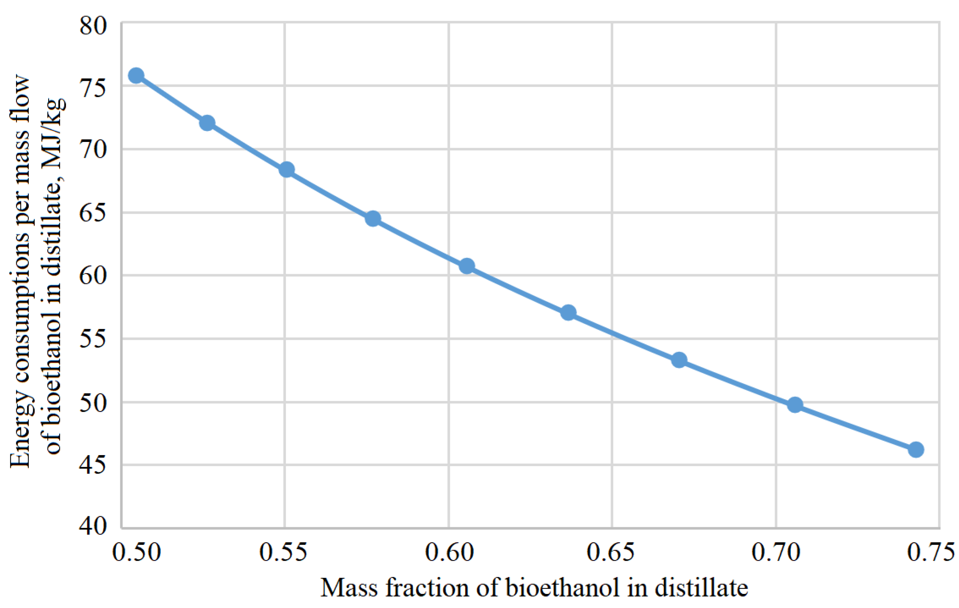
Figure 8 presents the dependence between energy consumptions per mass flow of bioethanol in the distillate, MJ/kg, and mass fraction of bioethanol in the distillate. Additionally,
Figure 9 shows the dependence between energy consumptions per mass flow of bioethanol in bottoms, MJ/kg, and mass fraction of bioethanol in bottoms.
Notably, for the alcohol column, energy consumption for heating bottoms per mass flow of the final product (bioethanol) averages 2.77 MJ/kg.
In
Table 5, the composition of Luther water and obtained bioethanol is presented in detail.
4. Discussion
According to the results presented above, the mass fraction of bioethanol (from 0.505 to 0.743) at different production stages is not the primary criterion for determining the energy consumption of heating steam directly. However, the following conclusions can be stated. Firstly, for the rectification column with the initial data presented in
Table 2, the minimum steam is 6 kg/s, equivalent to 79.7 MJ/s. Thus, a mixture of mass fraction of bioethanol of 0.74 and impurities of 0.09 has been obtained. With a lower steam flow rate, the column is not operating rationally.
Secondly, in the epuration column, under the obtained output data from the simulation of the brew column, the minimum steam consumption is 1.3 kg/s, which is equivalent to 17.3 MJ/s. The mixture has been obtained in bottoms with the mass fraction of bioethanol of 0.46 and impurities of 0.022. The column will not be operating for less steam consumption.
Thirdly, for the alcohol column, under the obtained output data from the calculation of the epuration column, the minimum steam consumption is 4 MJ/s. In this case, the mass fraction of distillate of 0.969 and impurities of 0.027 have been obtained. The proper operation of the column is not possible for lower energy consumption.
Thus, for second-generation bioethanol production using cereal straw as raw material with 270,000 tons/year, bioethanol of about 50,000 tons/year can be obtained with its mass fraction of 0.969. Notably, it is necessary to spend energy of at least 100.9 MJ/s on the rectification unit (i.e., brew, epuration, and alcohol columns).
Given the obtained results, the proposed approach for modeling technological processes for a rectification plant in second-generation bioethanol production can be discussed in terms of its advantages over recent research works. Notably, in the article [
28], ways to increase the profitability of bioethanol production due to the simultaneous saccharification process and fermentation are proposed. However, it is necessary to ensure a temperature mode above 40 °C. Such a temperature reduces the viability of traditional yeast culture and requires the use of specialized thermotolerant yeasts. As a result, the use of ethanolic yeasts “Kluyveromyces Marxianus” has been suggested. Such an approach can be used to reduce wastes in the considered second-generation bioethanol production process.
Moreover, only microbiological processes of second-generation bioethanol production are considered. In paper [
29], second-generation bioethanol production is considered using the waste of the pulp and paper industry as a raw material. Simultaneously, an attempt was made to use raw materials to increase the amount of waste comprehensively. However, only the fermentation process was studied. This technology justifies our approach, in which it is possible to use the distillation section of the first-generation technology as an element of second-generation bioethanol production.
Besides, the research work [
30] considers the prospects for applying membrane technologies in the process of obtaining bioethanol. In such a technology, ultrafiltration is used at the first stage and membrane distillation at the second one. Thus, only hydromechanical processes were considered. However, even though such membrane technologies can be applied at the last ultrafiltration stage, they require high costs for regeneration and replacement of consumables. Notably, our technology uses mainly continuous processes that are free of these disadvantages.
Moreover, in contrast to these research works, our article studies the most energy-intensive chemical-technological issues of second-generation bioethanol production, including modeling heat and mass transfer processes.
Article [
31] dials with the assessment of second-generation bioethanol production from sugar cane by modeling technological processes. Additionally, a detailed analysis of bioethanol production methods for different raw materials (e.g., sugar, starch, lignocellulose) is presented in paper [
2]. As a result, it has been shown that bioethanol can be an alternative fuel. Due to relatively high production costs, such a biofuel is not competitive with fossil fuels. However, the obtained data proved the ability to obtain additional water-alcohol solutions as a feedstock for bioethanol production.
In contrast to these studies, our article allows one to analyze energy consumptions of the boiled steam per mass flow rate of bioethanol in the distillate. Mainly, the consumption of boiler steam is a variable parameter during the modeling. Moreover, despite previous studies mentioned above, the authors of the article have assessed the possibility of using a multicolumn heat and mass transfer section of the first-generation bioethanol production technology to process second-generation raw materials to obtain accompanying ether aldehydes for commercial use. Notably, the value of such substances for the cosmetic and perfumery industries significantly exceeds the cost of bioethanol.
Finally, further studies will aim to create a computer program to evaluate energy consumption boundaries in second-generation bioethanol production and patent energy-efficient heat and mass transfer devices.
5. Conclusions
Thus, the obtained results have allowed us to solve applied scientific problems of technological optimization and rational designing to evaluating energy consumption in bioethanol production. As a result, the authors have evaluated a range of heating steam consumption for providing heat and mass transfer processes of bioethanol concentration.
The obtained results will help design plants based on the considered technology since by-products are also highly valuable in the global market of biofuel. However, it is impossible to determine the universal or optimal characteristics for the rectification unit. This fact is due to lignocellulosic materials varying in different countries, which affects the final cost of biofuels and their by-products.
The proposed analysis of technological parameters in biofuel production has shown that it is a powerful tool for estimating energy costs at each stage of the process. From the researched data, it is possible to choose an operational mode of the equipment for obtaining final products (e.g., fuel ethanol and impurities) under minimum energy consumption.
Finally, the availability of lignocellulosic materials will allow one to develop and increase the international market of biofuels and reduce greenhouse gas emissions worldwide. Recently, the authors, jointly with JSC “Ukrhimproekt” (Sumy, Ukraine), have designed the pre-project in biofuel production according to the PROESA™ biorefinery platform technology with the technology owner/licensor “Beta Renewables” (Crescentino, Italy).


 ,
, 


