
An Investigation of Ultrasonic-Assisted Electrochemical Machining of Micro-Hole Array


Department of Mechanical Engineering, National Central University, Taoyuan 32001, Taiwan
*
Author to whom correspondence should be addressed.
Processes 2021, 9(9), 1615; https://0-doi-org.brum.beds.ac.uk/10.3390/pr9091615
Submission received: 12 August 2021
/
Revised: 2 September 2021
/
Accepted: 6 September 2021
/
Published: 8 September 2021
(This article belongs to the Special Issue New Frontiers in Magnetic Polishing and Electrochemical Technology)
Abstract
:This paper uses an ultrasonic vibration-integrated array electrode for 301 stainless steel micro-hole drilling. The influence of machining parameters such as ultrasonic vibration amplitude, working voltage, pulse-off time and electrode feed rate on different processing characteristics are discussed. The experimental results show that the ultrasonic-assisted electrode array vibrating generates a periodic pressure difference for the electrolyte. The periodic pressure difference forms a pumping effect and a cavitation effect. The two effects can effectively renew the electrolyte in the machining gap and discharge the reaction product, gas and reaction heat from the gap. Machining speed can be increased by over 500% when the ultrasonic amplitude increases from 0.94 μm to 2.87 μm. Micro-hole drilling with the optimum experimental parameter combination of ultrasonic amplitude 2.87 μm, working voltage 11 V, pulse-off time 50 μs and electrode feed rate 5 μm/s can result in a minimum average diagonal length and a smaller amount of variation in diagonal length. It also improves the inlet and outlet taper angle of micro-holes.
1. Introduction
Nontraditional machining methods include electrochemical machining, electrochemical discharge machining, abrasive jet machining, water jet machining, etching machining, ultrasonic machining, laser machining, etc. The characteristics of electrochemical machining technology include the machining performance being free from the constraint of mechanical performance of the material, almost no wear on the tool electrode, high machining speed, good surface quality after machining, no heat-affected zone, no burrs and residual stress. Therefore, it is often used in the semiconductor industry, the automobile industry, the biomedical industry and other industrial processes. Because of the increase in processing demand for advanced materials, research into electrochemical machining technology has increased. When electrochemical machining technology is used in micro machining, as the tool electrode is microsized, it is hard to design an electrolyte supply flow channel system in the electrode. In the narrow machining gap, the gas bubbles, metal oxide and reaction heat, which results from the electrochemical reaction, are difficult to remove by electrolytes. Therefore, machining accuracy and surface quality deteriorate. Moreover, the short circuit of the two poles may damage the tool electrode and work-piece. According to the literature, many scholars propose using ultra-short pulse (nanosecond-scale) voltage [1,2,3,4], special feed mode [5], low-frequency electrode vibration [3,6,7] or a rotating spiral electrode [8,9] to solve the electrolyte renewal problem in the machining gap. However, the these methods have higher equipment costs and cannot enhance accuracy and surface quality significantly. Moreover, these methods lead to lower practicability and economy.
The present industry seeks a high-efficiency machining method. Some scholars propose using microelectrode array electrodes for batch electrochemical machining [10,11,12,13] in order to increase machining efficiency. However, multiple electrodes cannot be rotated simultaneously. Furthermore, a flow channel system cannot be designed in the electrode. The electrolyte is difficult to renew. The reaction products such as metal oxide, gas bubbles and reaction heat in the inter-electrode gap cannot be discharged rapidly. The electric field and flow field in the inter-electrode gap change, and machining accuracy and surface quality deteriorate. This can result in machining not being possible due to a short circuit of the two poles. In an effort to improve productivity in the traditional machining of difficult-to-cut materials, some studies about the advantages of ultrasonic-assisted machining have been investigated [14,15,16,17]. Therefore, this study uses a high-frequency ultrasonic vibration assisted tool electrode for the innovative electrochemical machining of a micro-hole array. Ultrasonic vibration generates a pumping effect and cavitation effect on the electrolyte. The former generates an extrusion effect on the overall machining gap and the latter generates a micro-range of micro-jet. The electrolyte is renewed by the two said effects. Reactive ions are supplemented as the electrolyte is renewed. Reaction products such as metal oxide, gas bubbles and reaction heat in the inter-electrode gap can be discharged rapidly. Machining speed and machining accuracy can be enhanced. This study performs a series of experiments. The influence of machining parameters such as ultrasonic vibration amplitude, working voltage, pulse-off time and electrode feed rate on different quality characteristics are also discussed. The processing characteristics include the average diagonal length, the amount of variation in diagonal length and hole wall morphology of a micro-hole array. We performed this study in order to achieve the purpose of improving micro-hole array machining accuracy and machining speed.
1.1. Ultrasonic Effect
The integrated electrode array is vibrated by an ultrasonic tool holder in this experiment. The vibrated electrode array promotes a pumping effect and a cavitation effect in the electrolyte. The aforementioned two effects are explained as follows.
1.1.1. Pumping Effect
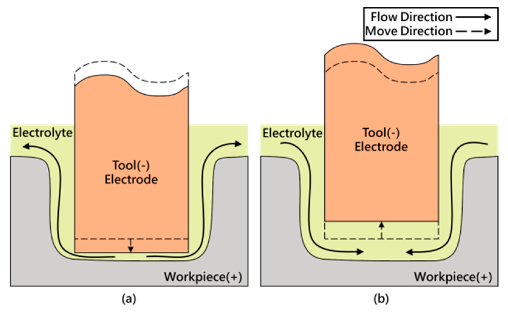
As the volume of electrolyte is incompressible, the tool electrode extrudes the electrolyte while vibrating up and down in the machining gap. The electrolyte is sucked in and discharged from the machining gap. This phenomenon is called the pumping effect, as shown in Figure 1.
1.1.2. Cavitation Effect
Fluid is the propagation medium of an ultrasound. The ultrasound changes the pressure of the medium rapidly. When the pressure of the medium is lower than the saturated vapor pressure, the medium changes from a boiling liquid into gas, forming microbubbles. When the pressure of the medium increases, the bubbles collapse, and the peripheral liquid rushes to the center of the bubbles. Thus, small but powerful micro-jets are generated.
2. Materials and Methods
2.1. Experimental Materials
2.1.1. Stainless Steel Work-Piece
The SUS 301 stainless steel work-piece used in this experiment is 60 mm long, 30 mm wide and 0.3 mm thick.
2.1.2. Integrated Array Tool Electrode
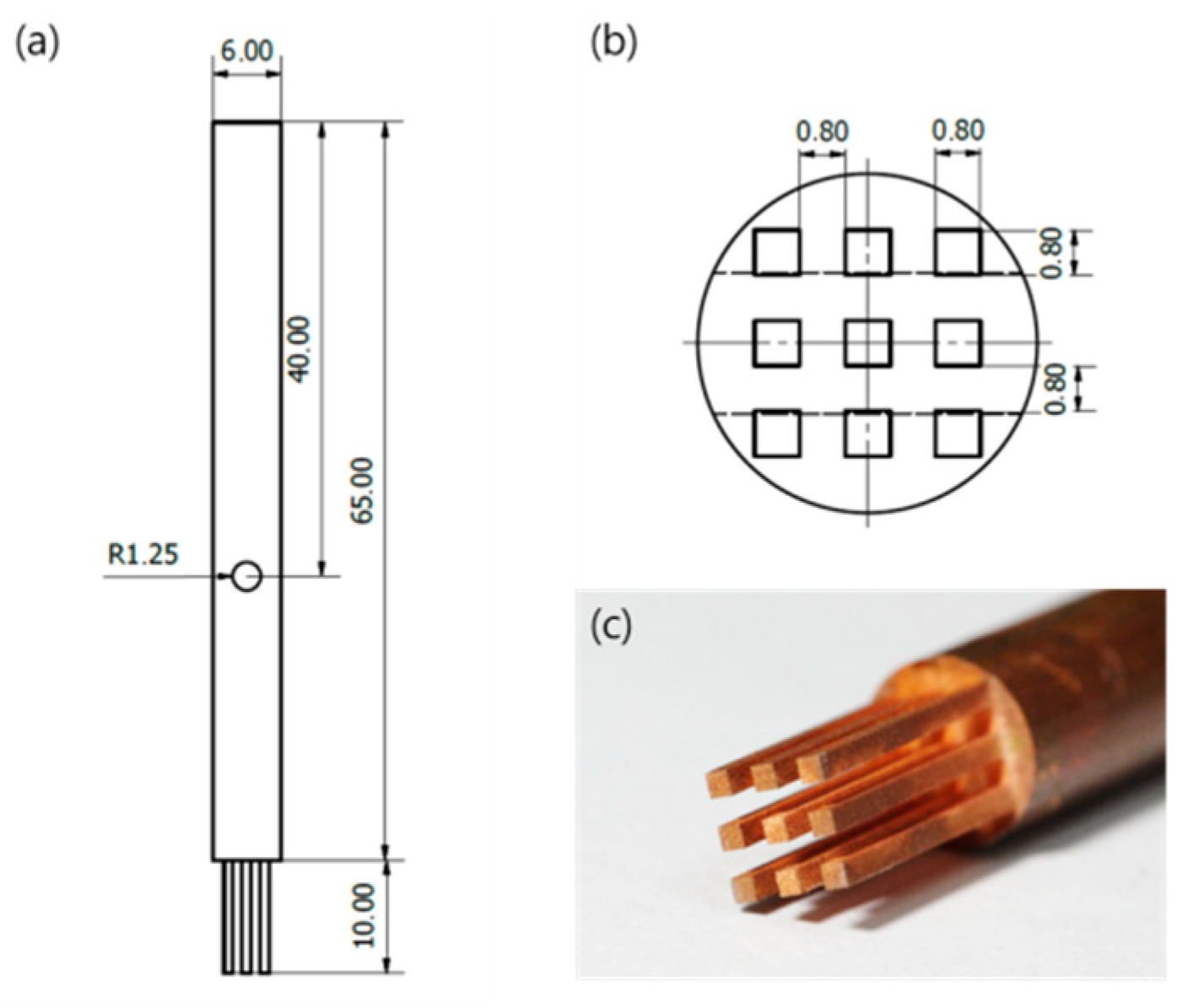
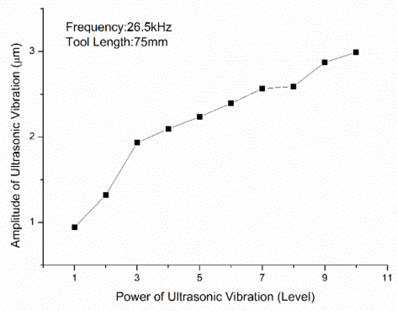
The integrated tool electrode array used in this experiment was machined by a wire electrical discharge machine, as shown in Figure 2. The specification of the copper tool electrode array is shown in Table 1. The integrated electrode array is vibrated by ultrasonic tool holder in this experiment. The ultrasonic tool holder was ACROW SL32-OLNR06-150 with an ultrasonic vibration frequency of 26.5 kHz in this experiment. Figure 3 shows the relationship between the power of ultrasonic vibration and the amplitude of ultrasonic vibration.
2.1.3. Electrolyte
In this experiment, sodium nitrate powder was added to pure water to form the electrolyte. The nitrate ions in the solution generated a passive film on the work-piece’s surface, so the machining precision was enhanced effectively. Based on the above advantages, the sodium nitrate electrolyte is suitable for micro-machining.
2.2. Experimental Instruments
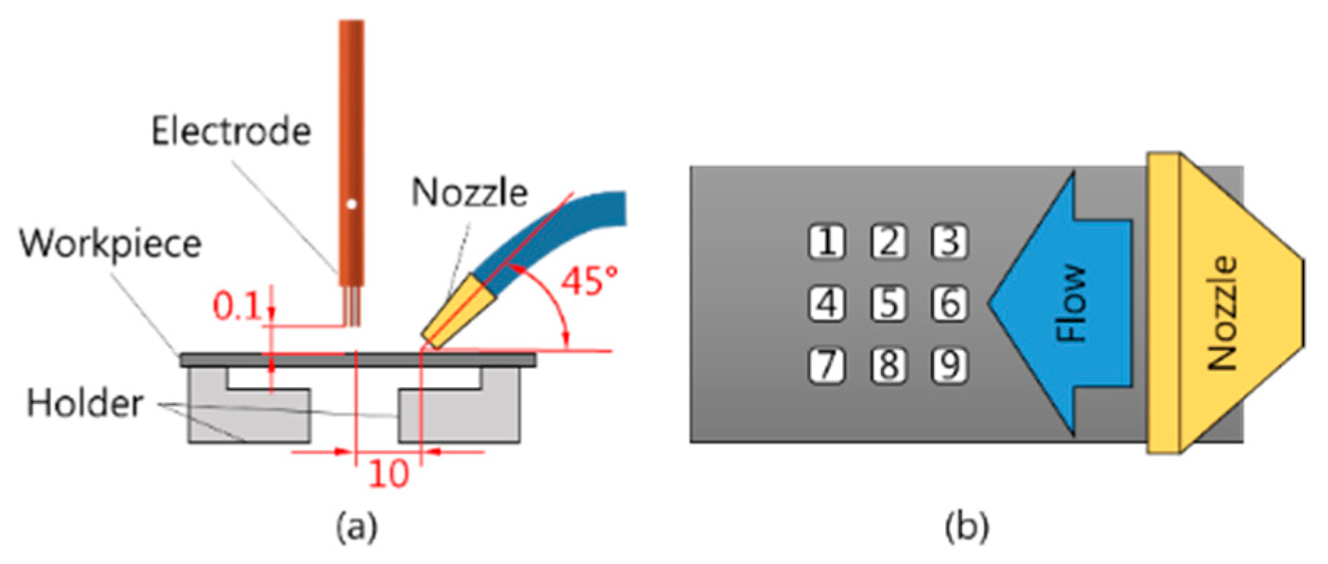
The experimental setup of this experiment is shown in Figure 4. The ultrasonic tool holder was settled on the Z-axis with a step motor, generating a Z-direction high-frequency vibration. The pulsed power supply was connected to the tool electrode array and work-piece. The working voltage and current waveforms during the machining were monitored by an oscilloscope. In the experimental process, the electrolyte must submerge the work-piece surface by approximately 10 mm. The snake tube with a flat nozzle was used for supplying the electrolyte, so the electrolyte jet flow range covered all array electrodes (Figure 5). The electrolyte was filtered by the electrolyte circulation system. The temperature of the electrolyte was controlled at 28 degrees before being pumped into the electrolytic tank.
2.3. Experimental Parameters and Measurement
The variation parameters and setting values of the experiments are shown in Table 2. The constant parameters and setting values of the experiments are shown in Table 3. Figure 6 shows the schematic diagram of the micro-hole array. The serial numbers of micro-holes are shown in Figure 6a. The numbers of the micro-holes in the following photos are arranged according to the numbers of the micro-holes in this schematic diagram. Figure 6b is an enlarged view of hole No. 1. This experiment uses a microscopic image measurement system to measure the micro-hole diagonal length. The micro-hole diagonal length is defined as follows:
where in D1 is the average of two diagonal lengths of hole No. 1, a1 and b1 are the two diagonal lengths of hole No. 1, respectively. The average diagonal length of the micro-hole array is defined as follows:
where Dave is the average diagonal length of micro-hole array.
The electrolyte flat nozzle was located at the right side of the electrolytic tank in this experiment, so the electrolyte in the machining gap of the right electrode was renewed the fastest. Therefore, the diagonal length of micro-holes generally decreases from right to left. The maximum diagonal length of the micro-hole array generally appeared in the No. 3, No. 6 and No. 9 holes of the right micro-holes. The minimum diagonal length of the micro-hole array generally appeared in the No. 1, No. 4 and No. 7 holes of the left micro-holes. The variation in diagonal length was defined as the difference between the maximum diagonal length and minimum diagonal length of the micro-hole array in this experiment. The variation in diagonal length was used to analyze the influence of various machining parameters on the diagonal length of the micro-hole array. Its calculation formula is expressed as follows:
where in Dvar is the variation in the micro-hole array, Dmax and Dmin are the maximum and minimum diagonal lengths of the micro-hole array, respectively. The Dvar represents the consistency of the array hole size.
3. Experimental Results and Discussion
3.1. Results of Conventional Electrochemical Machining of Micro-Hole Array
To study the influence of ultrasonic assistance on the electrochemical machining of different quality characteristics, we performed an experiment on the electrochemical machining of a micro-hole array without ultrasonic assistance. The experimental parameters are shown in Table 4.
Figure 7 shows a photo of the electrochemically machined work-piece without ultrasonic assistance. It was found that all the parameters failed to completely fabricate a 3 × 3 micro-hole array in the process without ultrasonic assistance. The machined work-piece surface is observed to have dark brown metal oxide accumulation. After the work-piece was cleaned by an ultrasonic cleaner, a special geometric feature was observed on the work-piece’s surface. The feature was scanned by a surface profilometer. The work-piece’s surface showed a central protrusion and surrounding depressions (Figure 7).
In the electrochemical machining of the micro-hole array without ultrasonic assistance, metal oxide accumulates in the machining gap at the tips of some single electrodes. It is difficult for the metal oxide in the central zone of these single electrodes t to be carried away by the flow of electrolytes. This phenomenon causes the resistance of the electrolyte in the central zone of the single electrode to be relatively higher than the resistance of the electrolyte in the peripheral region. The current flows in the path of less resistance. The central zone of the single electrode does not have enough current density to dissolve the material. The work-piece’s surface shows a central protrusion. Metal oxide eventually forms a thin film in the machining gap. The machining gaps between electrodes and the work-piece increase because of the thin film. The electric field intensity of these electrodes in the feed direction is decreased. The material dissolution in the feed direction is reduced. Finally, a complete micro-hole array cannot be performed when the stroke of the electrode array is finished [7].
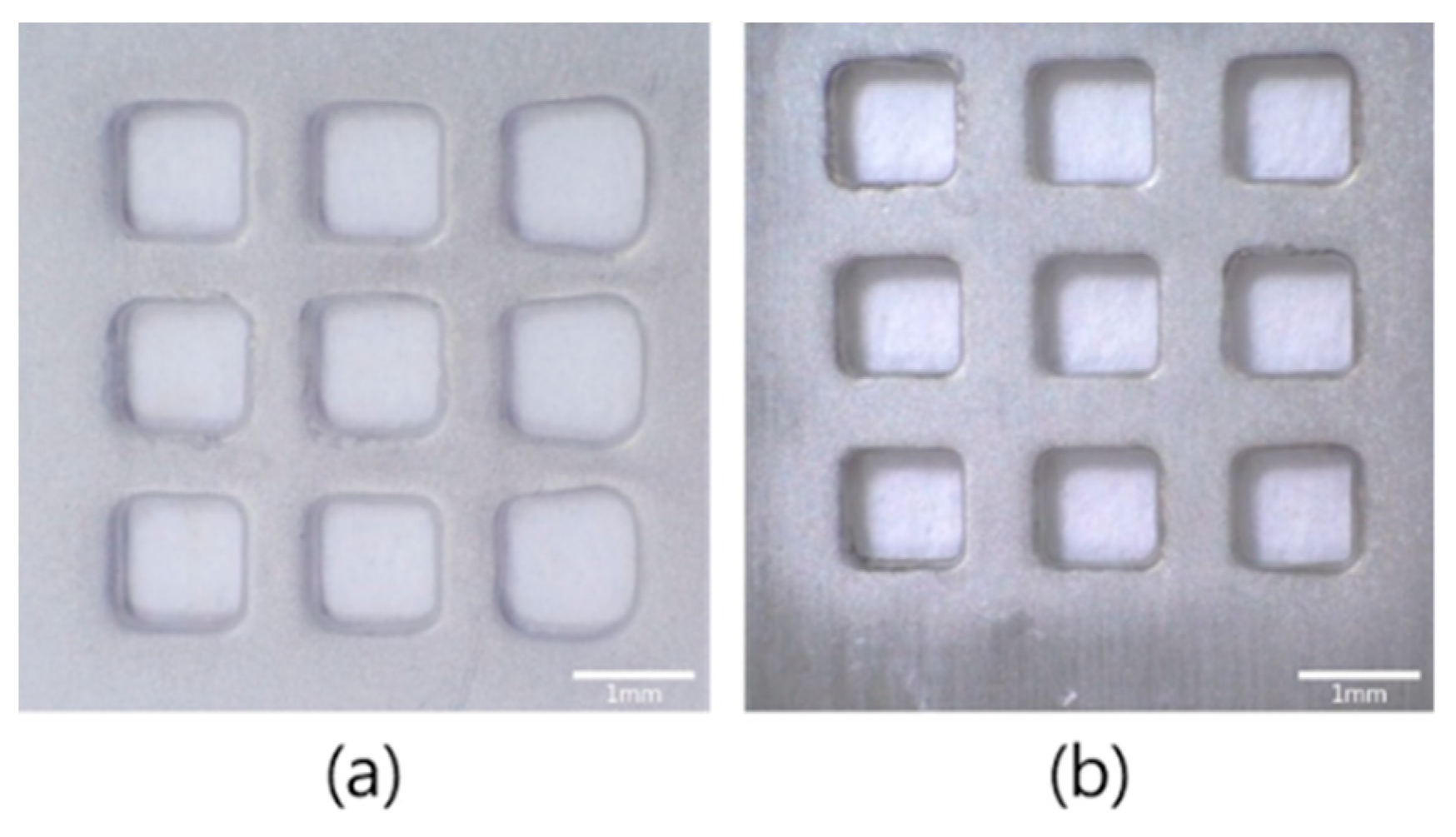
3.2. Influence of Electrolyte Jet on Machining Micro-Hole Array
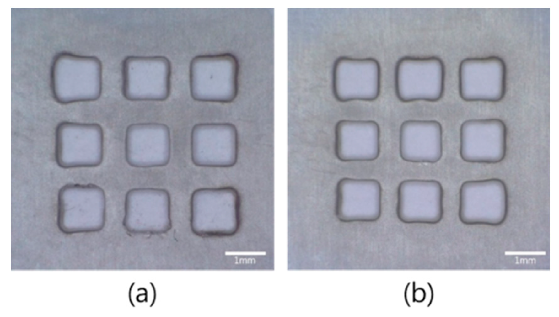
This experiment uses an integrated tool electrode array vibrated by an ultrasonic tool holder for the electrochemical machining of a micro-hole array. As the tool electrodes are microsized, it is difficult to dispose of a flow channel for supplying the electrolyte in the tool electrode. Each electrode also cannot be rotated simultaneously. Therefore, this experiment used a snake tube with a flat nozzle, as shown in Figure 5. The machined products in the machining zone are carried away by the flow of electrolytes and tool electrode vibration. The fresh electrolyte is supplied by an electrolyte jet. Tool electrode vibration supplements the ions into the machining zone. However, as the electrolyte jet is supplied from the right side of the array, as shown in Figure 5b, there will be differences in the electrochemical machining condition of each row of the micro-hole array. This results in different diagonal lengths of micro-holes.
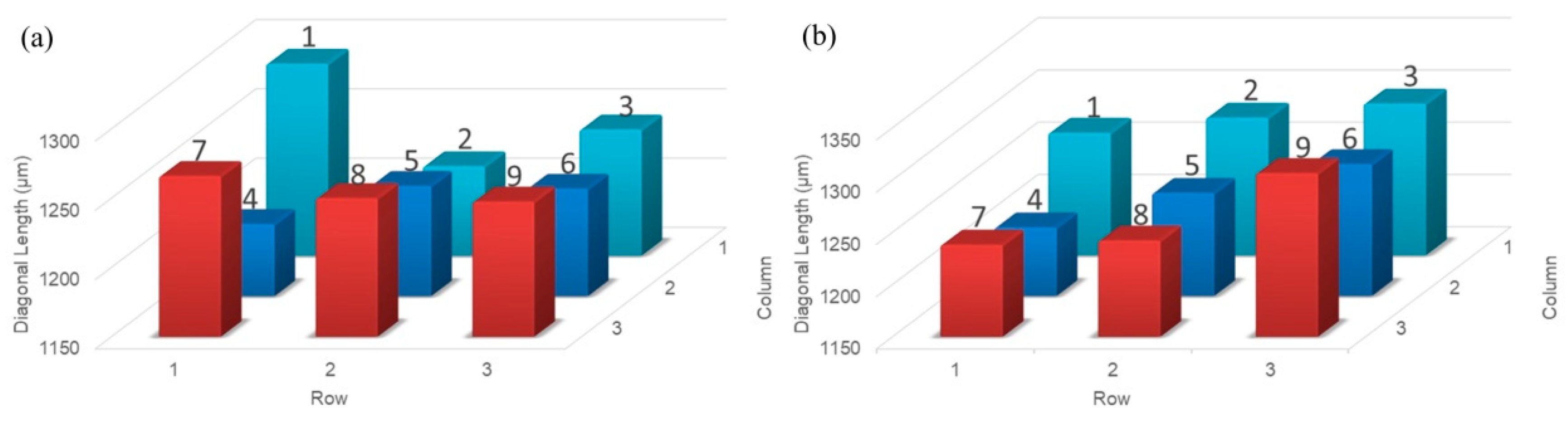
In order to study the influence of an electrolyte jet, an experiment on the electrochemical machining of a micro-hole array without an electrolyte jet was performed first (Figure 8a). The diagonal lengths of the micro-hole array are shown in Figure 9a. There is no specific rule of distribution of the micro-hole diagonal length in machining without an electrolyte jet. Figure 8b shows the machining result of using the electrolyte jet for supplying the electrolyte, and the diagonal lengths of the micro-hole array are shown in Figure 9b. The diagonal length of micro-holes of the array approximately decreases from right to left. The right side of the micro-hole array is directly flushed by an electrolyte jet, so that the reaction products can be more effectively discharged from the machining gap. The electrochemical dissolution rate at these holes is increased.
3.3. Influence of Ultrasonic Assistance on Machining Micro-Hole Array
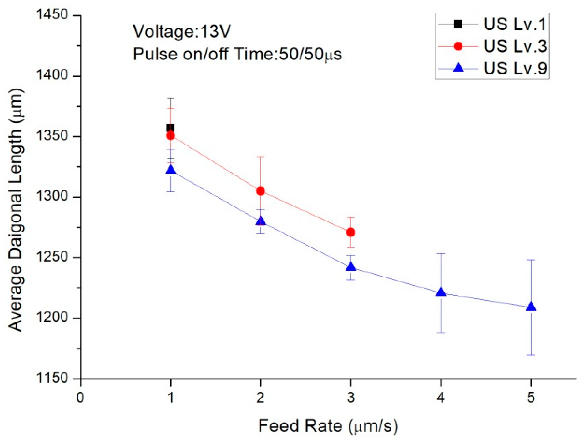
Figure 10 shows the relationship between different feed rates and average diagonal length under different ultrasonic amplitudes. As the electrode feed stroke is fixed in this experiment, the higher the electrode feed rate is, the shorter machining time required. The diagonal length of micro-holes generally decreases as machining time decreases. When the ultrasonic amplitude level 1 is used for the experiment, the renewal of electrolyte in the machining gap is worse than the renewal of electrolyte under the other ultrasonic level. When the feed rate is greater than 1 μm/s, this phenomenon causes a short circuit or perforation failure. As the ultrasonic amplitude is increased from level 1 to level 3, the ultrasonic vibrated tool electrode has a stronger ability to discharge the reaction products from the machining gap, so the electrode feed rate is allowed to be 3 μm/s. As the ultrasonic amplitude is level 9, the electrode feed rate is allowed to be 5 μm/s. Ultrasonic amplitude level 9 has a better machining capability.
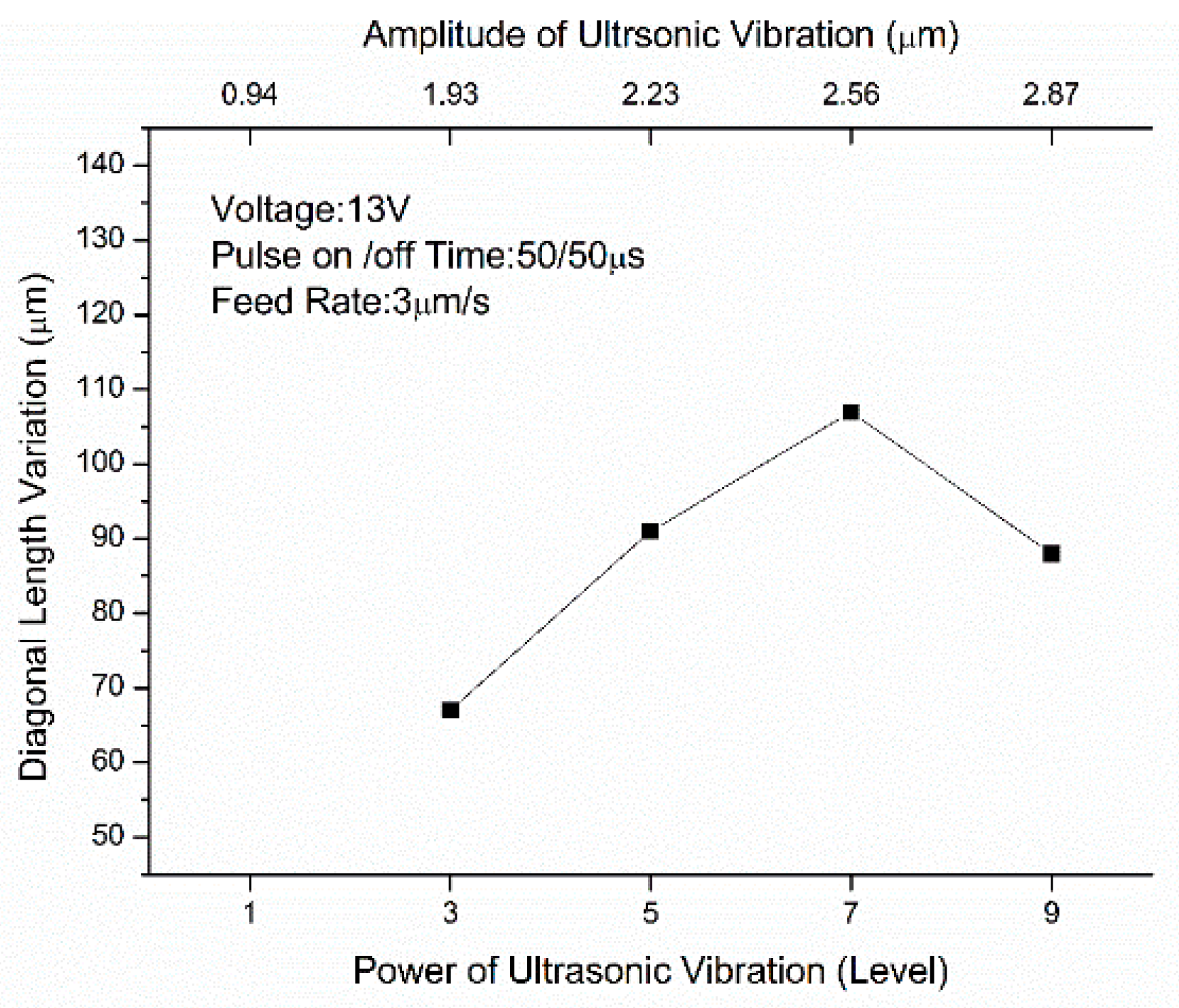
3.4. Influence of Ultrasonic Amplitude on Machining Micro-Hole Array
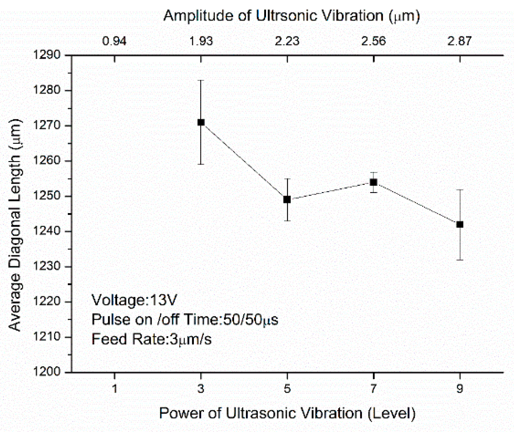
Figure 11 shows the relationship between different ultrasonic amplitudes and average diagonal length. When the ultrasonic amplitude is increased from level 3 to level 9, as shown in Figure 11, the average diagonal length is reduced from 1271 μm to 1242 μm. The larger the ultrasonic amplitude, is the higher the cavitation effect. The higher the proportion of bubbles in electrolyte to total volume is, the more likely it is for the electrical conductivity of the electrolyte to decrease. The electrochemical dissolution rate is also decreased, thereby reducing the average diagonal length of the array.
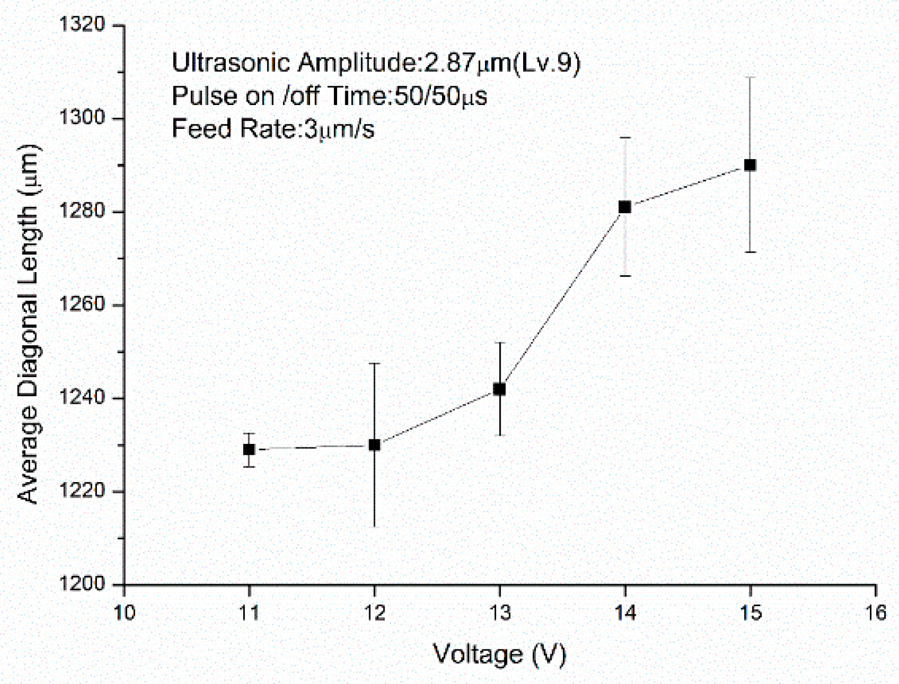
3.5. Influence of Working Voltage on Machining Micro-Hole Array
Figure 13 shows the relation between different working voltages and average diagonal length. It is observed in Figure 13 that, when the voltage increases from 11 V to 15 V, the average diagonal length increases from 1229 μm to 1290 μm. As the side face of the tool electrode used in this experiment is not insulated, the sidewall of micro-hole is dissolved by a continuous electrochemical reaction. The average diagonal length increases when the working voltage increases.
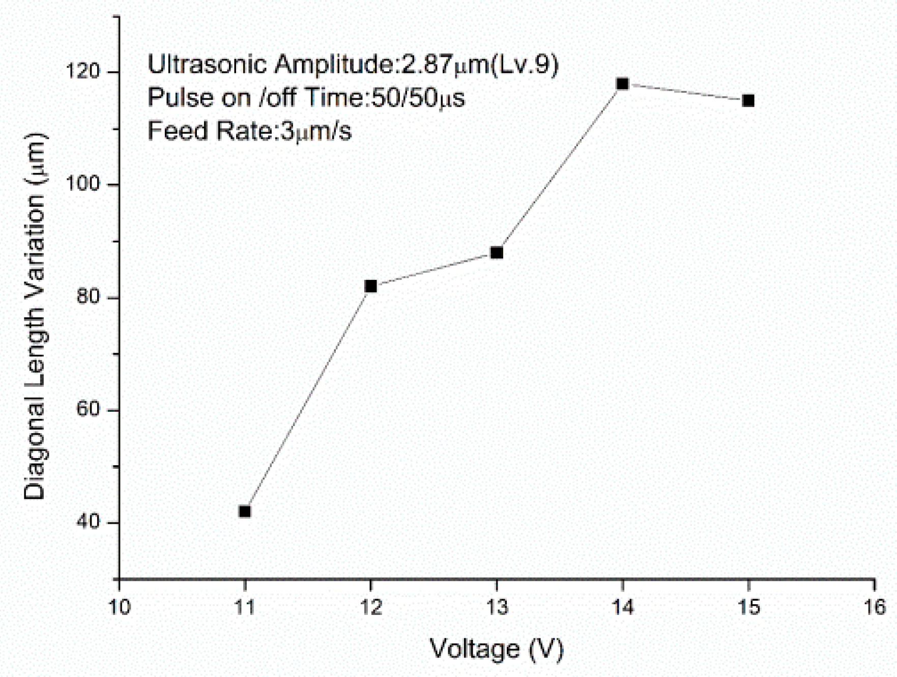
Figure 14 shows the relation between different working voltages and the amount of variation in diagonal length. As shown in Figure 14, when the working voltage increases from 11 V to 15 V, the amount of variation of diagonal length increases from 42 μm to 115 μm. The anodic dissolution rate is related to the electrical conductivity of the electrolyte, i.e., the voltage applied to two poles and its polarization potential. The holes in No. 3, No. 6 and No. 9 are supplied with sufficient electrolytes. When the machining gap contains many ions, the electrical conductivity of the electrolyte is higher. Holes No. 1, No. 4 and No. 7 have a worse electrolyte supply, the machining gap contains fewer ions and the electrical conductivity of the electrolyte is lower. The minimum value of diagonal length increases slightly with voltage due to the lower electrical conductivity of the electrolyte. The maximum value of diagonal length increases when working voltage increases, and the amount of variation in diagonal length also increases when working voltage increases.
3.6. Influence of Pulse-off Time on Machining Micro-Hole Array
Figure 15 shows the relation between different pulse-off times and average diagonal length. As shown in Figure 15, when the pulse-off time increases from 20 μs to 50 μs, the average diagonal length shortens from 1275 μm to 1223 μm. As the pulse-on time of this experiment is fixed at 50 μs, the longer the pulse-off time is, the lower the duty ratio is. this means that the power supply supplies less energy for electrochemical reaction. Therefore, the average diagonal length decreases as the pulse-off time increases.
Figure 16 shows the relation between different pulse-off times and the amount of variation of diagonal length. As shown in Figure 16, when the pulse-off time increases from 20 μs to 50 μs, the amount of variation in diagonal length shortens from 102 μm to 60 μm. The shorter the pulse-off time is, the higher the pulse duty ratio. Within the same machining time, the higher the pulse duty ratio is, the longer the voltage acting time. The amount of variation in diagonal length increases with machining time.
3.7. Influence of Electrode Feed Rate on Machining Micro-Hole Array
Figure 17 shows the photo of micro-hole arrays under feed rates 1 μm/s and 5 μm/s. As shown in Figure 17, when the feed rate increases from 1 μm/s to 5 μm/s, the stray current influence area is reduced. Figure 18 shows the relation between different electrode feed rates and the average diagonal length. As shown in Figure 18, when the electrode feed rate increases from 1 μm/s to 5 μm/s, the average diagonal length shortens from 1292 μm to 1200 μm. As the machining depth is fixed in this experiment, the machining time is inversely proportional to the electrode feed rate. Based on the above reason, the average diagonal length and the size of stray current influence area increase as the electrode feed rate decreases.
Figure 19 shows the relation between different feed rates and the amount of variation in diagonal length. As shown in Figure 19, when the electrode feed rate increases from 1 μm/s to 5 μm/s, the amount of variation in diagonal length shortens from 126 μm to 44 μm. As the machining time of electrode feed rate 5 μm/s is 1/5 that of feed rate 1 μm/s, the actual energy consumed by an electrochemical reaction at electrode feed rate 5 μm/s is less than that at electrode feed rate 1 μm/s. Thus, it can be seen that the higher the electrode feed rate is, the less total energy there is in the electrochemical reaction. The difference in the dissolution rate induced by electrolyte can be reduced. The amount of variation in diagonal length is also reduced.
Figure 20 shows a SEM image of the micro-hole array profile under different feed rates. According to the micro-hole profile of electrode feed rate 1 μm/s, the thickness of the hole wall edge is reduced due to the stray current corrosion effect. The tapered angle of the hole inlet is very large. The micro-hole of feed rate of 5 μm/s has a smaller inlet tapered angle due to its shorter machining time.
4. Conclusions
This study examines the ultrasonic-assisted electrochemical machining of a micro-hole array. The experimental results show that ultrasonic-assisted electrochemical machining can effectively enhance machining capability and machining speed. The average diagonal length and the tapered angles of the micro-hole can also be improved. The following conclusions are drawn.
- In the electrochemical machining of the micro-hole array with ultrasonic assistance, the electrolyte can be effectively renewed in the machining gap and the reaction product can be discharged from the gap. When the ultrasonic amplitude increases from level 1 to level 9, machining speed can be increased by over 500%.
- Working voltage is one of the key parameters that influence the machining gap in the feed direction and the lateral machining gap. When working voltage increases from 11 V to 15 V, the average diagonal length increases from 1229 μm to 1290 μm, and the amount of variation in diagonal length increases from 42 μm to 115 μm.
- When increasing the electrode feed rate and decreasing the duration of an electrochemical reaction, machining accuracy can be improved. When the electrode feed rate increases from 1 μm/s to 5 μm/s, the average diagonal length shortens from 1292 μm to 1200 μm, and the amount of variation in diagonal length decreases from 126 μm to 44 μm.
- Suitable working parameters for the ultrasonic-assisted process are an ultrasonic amplitude of level 9, a working voltage of 11 V, a pulse-off time of 50 μs and an electrode feed rate of 5 μm/s.
5. Patents
There are no patents resulting from the work reported in this manuscript.
Author Contributions
Conceptualization, Z.-Y.S. and H.-P.T.; Methodology, Z.-Y.S.; Data curation, Z.-Y.S.; Visualization, Z.-Y.S. and H.-P.T.; investigation, Z.-Y.S. and H.-P.T.; supervision, H.-P.T.; writing—review and editing, H.-P.T.; writing—original draft preparation, H.-P.T. All authors have read and agreed to the published version of the manuscript.
Funding
This research received no external funding.
Institutional Review Board Statement
Not applicable.
Informed Consent Statement
Informed consent was obtained from all subjects involved in the study.
Data Availability Statement
The data and materials are available.
Conflicts of Interest
The authors declare no conflict of interest.
References
- Rajurkar, K.P.; Levy, G.; Malshe, A.; Sundaram, M.; McGeough, J.; Hu, X.; Resnick, R.; DeSilva, A. Micro and nano machining by electro-physical and chemical processes. CIRP Ann. 2006, 55, 643–666. [Google Scholar] [CrossRef]
- Schuster, R.; Kirchner, V.; Allongue, P.; Ertl, G. Electrochemical micromachining. Science 2000, 289, 98–101. [Google Scholar] [CrossRef] [PubMed]
- Kozak, J.; Rajurkar, K.P.; Makkar, Y. Selected problems of micro-electrochemical machining. J. Mater. Process. Technol. 2004, 149, 426–431. [Google Scholar] [CrossRef]
- Ahn, S.H.; Ryu, S.H.; Choi, D.K.; Chu, C.N. Electro-chemical micro drilling using ultra short pulses. Precis. Eng. 2004, 28, 129–134. [Google Scholar] [CrossRef]
- Hewidy, M.; Ebeid, S.; Rajurkar, K.P.; El-Safti, M. Electrochemical machining under orbital motion conditions. J. Mater. Process. Technol. 2001, 109, 339–346. [Google Scholar] [CrossRef]
- Natsu, W.; Nakayama, H.; Yu, Z. Improvement of ecm characteristics by applying ultrasonic vibration. Int. J. Precis. Eng. Manuf. 2012, 13, 1131–1136. [Google Scholar] [CrossRef]
- Bradley, C.; Samuel, J. Controlled phase interactions between pulsed electric fields, ultrasonic motion, and magnetic fields in an anodic dissolution cell. J. Manuf. Sci. Eng. 2018, 140, 041010. [Google Scholar] [CrossRef] [Green Version]
- Tsui, H.P.; Hung, J.C.; You, J.C.; Yan, B.H. Improvement of electrochemical microdrilling accuracy using helical tool. Mater. Manuf. Process. 2008, 23, 499–505. [Google Scholar] [CrossRef]
- Yang, Y.K. A Study on Magnetic Field Assisted Micro Electro-Chemical Milling; National Central University: Taoyuan, Taiwan, 2009. [Google Scholar]
- Park, M.S.; Chu, C.N. Micro-electrochemical machining using multiple tool electrodes. J. Micromech. Microeng. 2007, 17, 1451. [Google Scholar] [CrossRef]
- Wang, M.; Zhu, D. Fabrication of multiple electrodes and their application for micro-holes array in ecm. Int. J. Adv. Manuf. Technol. 2009, 41, 42–47. [Google Scholar] [CrossRef]
- Skrabalak, G.; Stwora, A. Electrochemical, electrodischarge and electrochemical-discharge hole drilling and surface structuring using batch electrodes. Procedia CIRP 2016, 42, 766–771. [Google Scholar] [CrossRef]
- Arab, J.; Adhale, P.; Mishra, D.K.; Dixit, P. Micro-hole array formation in glass using electrochemical discharge machining. Procedia Manuf. 2019, 34, 349–354. [Google Scholar] [CrossRef]
- Wu, B.; Zhao, B.; Ding, W.; Su, H. Investigation of the wear characteristics of microcrystal alumina abrasive wheels during the ultrasonic vibration-assisted grinding of ptmcs. Wear 2021, 477, 203844. [Google Scholar] [CrossRef]
- Zhang, X.; Yang, L.; Wang, Y.; Lin, B.; Dong, Y.; Shi, C. Mechanism study on ultrasonic vibration assisted face grinding of hard and brittle materials. J. Manuf. Process. 2020, 50, 520–527. [Google Scholar] [CrossRef]
- Suárez, A.; Veiga, F.; de Lacalle, L.N.L.; Polvorosa, R.; Lutze, S.; Wretland, A. Effects of ultrasonics-assisted face milling on surface integrity and fatigue life of ni-alloy 718. J. Mater. Eng. Perform. 2016, 25, 5076–5086. [Google Scholar] [CrossRef]
- Ainhoa, C.; Luis, N.L.L.; Francisco, J.C.; Aitzol, L. Ultrasonic Assisted Turning of mild steels. Int. J. Mater. Prod. Technol. 2010, 37, 60–70. [Google Scholar]
Figure 1.
Schematic diagram of ultrasonic pumping effect: (a) tool electrode moving downward; (b) tool electrode moving upward.
Figure 1.
Schematic diagram of ultrasonic pumping effect: (a) tool electrode moving downward; (b) tool electrode moving upward.

Figure 2.
Photo of integrated tool electrode array:(a) front view; (b) bottom view; (c) photo of integrated array tool electrode.
Figure 2.
Photo of integrated tool electrode array:(a) front view; (b) bottom view; (c) photo of integrated array tool electrode.

Figure 3.
The relationship between power of ultrasonic vibration and amplitude of ultrasonic vibration.
Figure 3.
The relationship between power of ultrasonic vibration and amplitude of ultrasonic vibration.

Figure 4.
Schematic diagram of the experimental setup.

Figure 5.
Schematic diagram of snake tube with flat nozzle for supplying electrolytes: (a) front view; (b) top view.
Figure 5.
Schematic diagram of snake tube with flat nozzle for supplying electrolytes: (a) front view; (b) top view.

Figure 6.
The schematic diagram of the micro-hole array:(a) top view; (b) enlarged view of the hole.
Figure 6.
The schematic diagram of the micro-hole array:(a) top view; (b) enlarged view of the hole.

Figure 7.
Photo of electrochemically machined work-piece without ultrasonic assistance: (a) scanning area framed by red line; (b) scanned photo by surface profilometer.
Figure 7.
Photo of electrochemically machined work-piece without ultrasonic assistance: (a) scanning area framed by red line; (b) scanned photo by surface profilometer.

Figure 8.
Photo of electrochemical machining of micro-hole array: (a) without electrolyte jet; (b) with electrolyte jet.
Figure 8.
Photo of electrochemical machining of micro-hole array: (a) without electrolyte jet; (b) with electrolyte jet.

Figure 9.
Diagonal lengths of micro-hole array: (a) without electrolyte jet; (b) with electrolyte jet.
Figure 9.
Diagonal lengths of micro-hole array: (a) without electrolyte jet; (b) with electrolyte jet.

Figure 10.
The relationship between different feed rates and average diagonal length under different ultrasonic amplitudes.
Figure 10.
The relationship between different feed rates and average diagonal length under different ultrasonic amplitudes.

Figure 11.
The relationship between different ultrasonic amplitudes and average diagonal length.

Figure 12.
The relation between different ultrasonic amplitudes and the amount of variation in diagonal length.
Figure 12.
The relation between different ultrasonic amplitudes and the amount of variation in diagonal length.

Figure 13.
The relation between different working voltages and average diagonal length.

Figure 14.
The relation between different working voltages and the amount of variation in diagonal length.
Figure 14.
The relation between different working voltages and the amount of variation in diagonal length.

Figure 15.
The relation between different pulse-off times and average diagonal length.

Figure 16.
The relation between different pulse-off times and the amount of variation in diagonal length.
Figure 16.
The relation between different pulse-off times and the amount of variation in diagonal length.

Figure 17.
Photo of micro-hole arrays under different feed rate: (a) feed rate 1 μm/s; (b) feed rate 5 μm/s.
Figure 17.
Photo of micro-hole arrays under different feed rate: (a) feed rate 1 μm/s; (b) feed rate 5 μm/s.

Figure 18.
The relation between different electrode feed rates and the average diagonal length.

Figure 19.
The relation between different feed rates and the amount of variation in diagonal length.
Figure 19.
The relation between different feed rates and the amount of variation in diagonal length.

Figure 20.
The SEM image of micro-hole array profile under different feed rates.


Table 1.
The specification of the 3 × 3 tool electrode array.
| Parameters | Description |
|---|---|
| Tool electrode length (mm) | 75 |
| Tool electrode tip size (mm) | 0.8 × 0.8 |
| Tool electrode tip diagonal length (mm) | 1.13 |
| Tool electrode tip length (mm) | 10 |
| Distance between two tool electrode tips (mm) | 0.8 |
Table 2.
The variation parameters and setting values of the experiments.
| Parameters | Value |
|---|---|
| Ultrasonic vibration amplitude (level/μm) | 3/1.93, 5/2.23, 7/2.56, 9/2.87 |
| Working voltage (V) | 11, 12, 13, 14, 15 |
| Pulse-off time (τoff, μs) | 20, 30, 40, 50, 60 |
| Electrode feed rate (μm/s) | 1, 2, 3, 4, 5 |
Table 3.
The constant parameters and setting values of the experiments.
| Parameters | Value |
|---|---|
| Tool electrode stroke (µm) | 450 |
| Initial machining gap (µm) | 100 |
| Pulse-on time (τon, μs) | 50 |
| ultrasonic vibration frequency (kHz) | 26.5 |
| Electrolyte concentration (wt%) | 10 |
| Electrolyte temperature (°C) | 30 |
| Electrolyte jet pressure (Psi) | 1 |
| Distance from work-piece surface (mm) | 10 |
Table 4.
The experimental parameters for electrochemical machining without ultrasonic assistance.
| Parameters | Value |
|---|---|
| Working voltage (V) | 11, 12, 13, 14, 15 |
| Pulse-on/Pulse-off time (τon/τoff, μs) | 50/50 |
| Electrode feed rate (μm/s) | 1 |
| Initial machining gap (µm) | 100 |
| Tool electrode stroke (µm) | 450 |
Publisher’s Note: MDPI stays neutral with regard to jurisdictional claims in published maps and institutional affiliations. |
© 2021 by the authors. Licensee MDPI, Basel, Switzerland. This article is an open access article distributed under the terms and conditions of the Creative Commons Attribution (CC BY) license (https://creativecommons.org/licenses/by/4.0/).
Share and Cite
MDPI and ACS Style
Shen, Z.-Y.; Tsui, H.-P. An Investigation of Ultrasonic-Assisted Electrochemical Machining of Micro-Hole Array. Processes 2021, 9, 1615. https://0-doi-org.brum.beds.ac.uk/10.3390/pr9091615
AMA Style
Shen Z-Y, Tsui H-P. An Investigation of Ultrasonic-Assisted Electrochemical Machining of Micro-Hole Array. Processes. 2021; 9(9):1615. https://0-doi-org.brum.beds.ac.uk/10.3390/pr9091615
Chicago/Turabian StyleShen, Zhe-Yong, and Hai-Ping Tsui. 2021. "An Investigation of Ultrasonic-Assisted Electrochemical Machining of Micro-Hole Array" Processes 9, no. 9: 1615. https://0-doi-org.brum.beds.ac.uk/10.3390/pr9091615
Note that from the first issue of 2016, this journal uses article numbers instead of page numbers. See further details here.