Temperature Uniformity in Cross-Flow Double-Layered Microchannel Heat Sinks


Dipartimento Politecnico di Ingegneria e Architettura, Università degli Studi di Udine, 33100 Udine, Italy
*
Author to whom correspondence should be addressed.
†
These authors contributed equally to this work.
Fluids 2020, 5(3), 143; https://0-doi-org.brum.beds.ac.uk/10.3390/fluids5030143
Submission received: 29 July 2020
/
Revised: 24 August 2020
/
Accepted: 25 August 2020
/
Published: 28 August 2020
(This article belongs to the Special Issue Recent Advances in Single and Multiphase Flows in Microchannels)
Abstract
:An in-house finite element method (FEM) procedure is used to carry out a numerical study on the thermal behavior of cross-flow double-layered microchannel heat sinks with an unequal number of microchannels in the two layers. The thermal performance is compared with those yielded by other more conventional flow configurations. It is shown that if properly designed, i.e., with several microchannels in the top layer smaller than that in the bottom layer, cross-flow double-layered microchannel heat sinks can provide an acceptable thermal resistance and a reasonably good temperature uniformity of the heated base with a header design that is much simpler than that required by the counter-flow arrangement.
1. Introduction
The feasibility of effectively using liquid cooled microchannel heat sinks (MCHS) for the thermal control of electronic devices was established in the early 1980s by Tuckerman and Pease [1], who designed and tested a new, very compact, water-cooled integral heat sink for silicon integrated circuits consisting of a single layer of parallel microchannels. Since then, many researchers carried out extensive research seeking alternative solutions to obtain improved thermal performance. Earlier studies aimed at MCHS optimization were based on the use of correlations to estimate the Nusselt number at the liquid-solid interface of the microchannels [2]. Analytical methods were also used for optimization purposes [3], but most of more recent analyses were carried out experimentally or numerically, or both. Li and Peterson [4] developed a full 3-D conjugate heat transfer model to assess the heat transfer performance of silicon-based, parallel MCHSs. They found that, for a given pumping power, the overall cooling capacity could be significantly enhanced using optimized spacing and channel dimensions. Kuo et al. [5] numerically investigated the effects of design variables, namely the channel width and height, on the thermal resistance of the MCHS. In particular, they found that the optimal channel width strongly depends on the channel height only when the flow power is below a certain value. Qu and Mudawar [6] carried out an experimental and numerical study and showed that the conventional Navier–Stokes and energy equations can adequately predict the fluid flow and heat transfer characteristics of microchannel heat sinks. Chiu et al. [7] also numerically and experimentally investigated the thermal performance of liquid cooled MCHSs and concluded that the effective thermal resistance remains almost constant when the cross-sectional porosity varies within a certain range. Other attempts to improve the thermal behavior of liquid cooled MCHSs included the use of grooved [8] or corrugated [9] microchannels. A comprehensive review is reported in the work of Adham et al. [10].
Over twenty years ago, Vafai and Zhu [11] proposed a double-layered microchannel heat sink (DL-MCHS) with a counter-current flow arrangement. In more recent years, Wei et al. [12] fabricated and tested a DL-MCHS and found that, even if parallel flow might yield the best performance in reducing the peak temperature, the counterflow configuration provides better temperature uniformity, which is important for thermal stress control. Since then, many optimization studies were carried out both analytically [13] and numerically [14,15,16,17,18,19,20,21,22,23,24]. Levac et al. [14] compared the thermal behavior of single-layered and double-layered MCHSs with both parallel flow and counter-flow arrangements. They found that the counter-flow configuration yields the best overall performance and the lowest thermal resistance with high Reynolds number flows, while at low Reynolds numbers the thermal resistance was lower with the parallel flow configuration. Similar conclusions were reached by Xie et al. [15,16] who also considered the effects of using wavy microchannels. Hung et al. [17,18] found that with the counter-flow arrangement the thermal performance could be improved if microchannels of different heights are used in the bottom and top layers. Similar conclusions were reached by Leng et al. [19] who also presented an improved DL-MCHS design with truncated microchannels in the top layer [20,21]. Kulkarni et al. [22] took the effects of temperature dependent thermophysical properties into account while carrying out the optimization of a double-layered MCHS. Wong and Ang [23] studied the effect of microchannel height contraction in a DL-MCHS and found that, while with tapered microchannels better thermal performance can be achieved as compared to those of the conventional design, the required pumping power becomes higher as the channel height contraction ratio increases. Wu et al. [24] carried out a parametric investigation on the thermal behavior of DL-MCHSs and observed that an inlet velocity in the microchannels of the upper layer smaller than that in microchannels of the bottom layer may result in the improvement of the overall performance at a given pumping power.
All the above referenced studies considered DL-MCHS where the microchannels of the two layers are aligned with either parallel or counter-flow arrangements. In fact, only very few and rather recent papers report results concerning the thermal performance of cross-flow DL-MCHSs where the flow in the microchannels of the bottom layer is perpendicular to the one in the microchannels of the top layer. Asnari and Kim [25] proposed the adoption of the transverse flow configuration, but they found that only with some modifications to the basic cross-flow arrangement it was possible to obtain improved performance with respect to those yielded by the more conventional design. The same authors concluded that a modified transverse flow arrangement, where each layer is subdivided into quarters with opposite flow directions in each quarter, exhibited the lowest thermal resistance and temperature variation in a case with non-uniform heating conditions with random hotspots [26]. Tang et al. [27] developed an optimization model of DL-MCHS and concluded that the counter-flow heat sinks yield better thermal performance as compared to cross-flow heat sinks for the same pumping power.
The superiority of the double-layered MCHS emerges from the above literature review since, in particular when the counter-flow configuration is adopted, it allows the achievement of a low thermal resistance and a good temperature uniformity of the heated base. However, this comes at the expense of a more complicated piping because a counter-flow DL-MCHS requires two separate inlets and two separate outlets on opposite sides. The improved transverse flow configuration proposed by Asnari and Kim [26] depends upon even more complicated manifolds. However, in previous articles the present authors showed that the inlet velocity maldistribution is always detrimental for the performance of a counter-flow DL-MCHS [28], while in some cases, it can help improve the thermal behavior of a basic cross-flow DL-MCHS [29]. In this paper, instead, a numerical investigation is carried out to show that a cross-flow DL-MCHS, if properly designed, can also guarantee an acceptable thermal resistance and a reasonably good temperature uniformity of the heated base independently of the flow maldistribution, with the advantage of allowing a very simple header arrangement, with only one inlet and one outlet placed on opposite sides. In particular, the effect of using a different number of microchannels in the two layers of a DL-MCHS is investigated and the thermal performance are compared to those yielded by the single-layered and the counter-flow double-layered configurations.
2. Statement of the Problem
To illustrate the concept of the cross-flow double-layered microchannel heat sink (DL-MCHS), the problem of cooling a square microchip with an area of 1.0 cm2 and a thermal power dissipation of 100 W is analyzed. The investigation is carried out with reference to a series of single- and double-layered MCHSs with a square footprint of mm2, equal to the area of the microchip, a number of microchannels in the bottom layer equal to 50 and several microchannels in the top layer which can be either equal to or less than 50. The following additional geometrical parameters are selected: microchannel height mm; microchannel width and wall thickness (horizontal and vertical) mm. The schemes shown in Figure 1 illustrate the eight configurations considered here, namely
- CF: double-layered counter-flow with ;
- XF: double-layered cross-flow with ;
- XF35: double-layered cross-flow with and ;
- XF30: double-layered cross-flow with and ;
- XF25: double-layered cross-flow with and ;
- XF20: double-layered cross-flow with and ;
- XF15: double-layered cross-flow with and ;
- SL: single-layered with and .
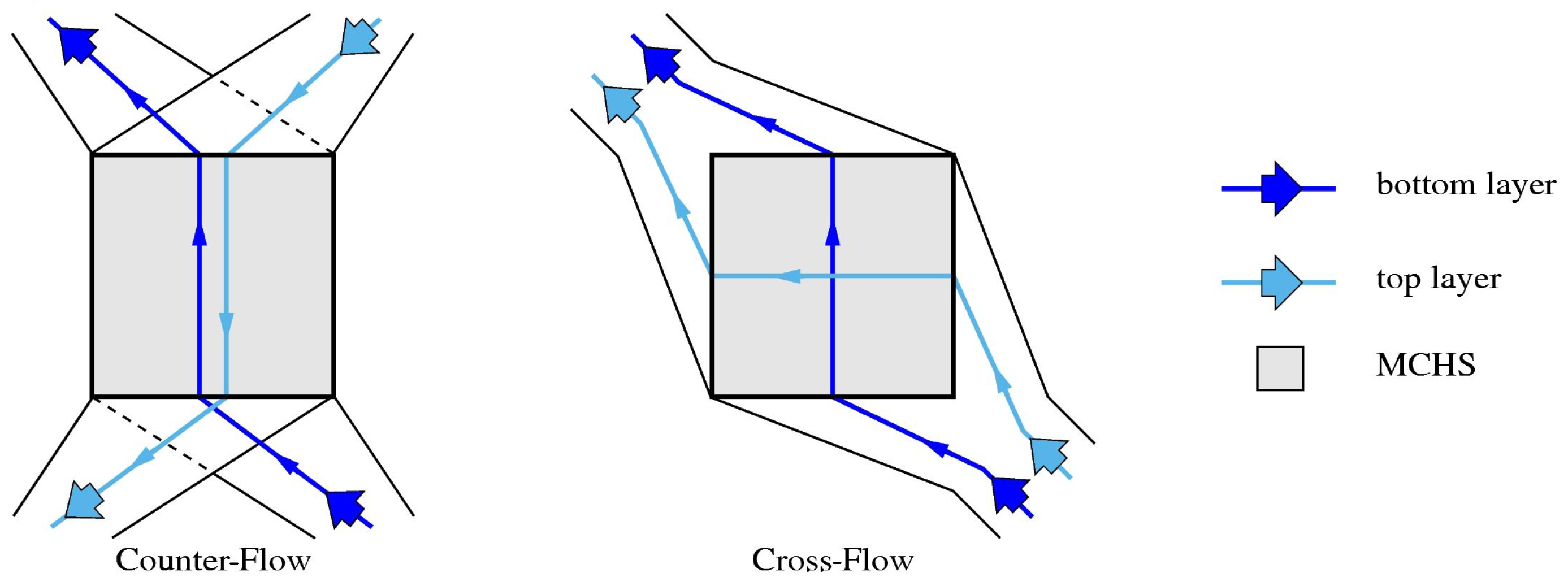
In Figure 1 the microchannels of the bottom layer are shown in dark blue, while those of the top layer appear in light blue. This color pattern is also adopted in the rest of the paper. In the cross-flow MCHSs with , the microchannels are placed closer to the side where the outlets of the microchannels of the bottom layer are located. Figure 2, where the shaded area represents the microchannel heat sinks (MCHS) and the header layouts are schematically represented together with the coolant paths for the two base flow configurations, illustrates the main advantage of adopting a cross-flow arrangement. In fact, as already mentioned, this allows the use of a piping with only one inlet and one outlet to feed both the top and the bottom layer which is less complicated than that required by the counter-flow configuration, that, obviously, can only be obtained with two separate inlets and two separate outlets.
The thermal boundary conditions are: uniform heat flux applied to the bottom (heated) wall W/cm2; adiabatic top and lateral walls; uniform fluid inlet temperature K. The MCHS material is silicon, with thermal conductivity W/(m K), while the coolant fluid is water, with density Kg/m3, dynamic viscosity kg/(m s), thermal conductivity W/(m K) and specific heat J/(kg K). Three values of the volumetric flow rate are considered: , and mL/s, yielding average microchannel velocities from m/s to m/s (depending on the total number of microchannels) and corresponding Reynolds numbers from 97 to 778 (laminar flow in all cases). The velocity distribution at the inlet of each microchannel is assumed to be uniform and equal for all the microchannels of the two layers in the MCHS. Therefore, the pressure drop will also be the same in all microchannels.
3. Numerical Procedure
The fluid flow and heat transfer in microchannel heat sinks as the ones described in the previous section are governed by the Navier-Stokes and the thermal energy equations which are solved here in the hypotheses of a constant property fluid and negligible diffusion of momentum in the axial direction. According to Shah and London the latter represents a reasonable assumption when the Reynolds number is larger than about 50 [30]. The hypothesis of a constant property fluid is justified because (i) in the test cases analyzed in the following the liquid coolant only undergoes limited temperature changes and (ii) the main purpose of this article is just to demonstrate the effectiveness of properly designed cross-flow MCHSs for microchip temperature management and not to carry out detailed calculations with reference to actual thermal devices.
A procedure, based on the standard Galerkin finite element method (FEM), was employed to solve the governing equations. The procedure consists of two in-house FEM codes. The first one is used to solve the Navier-Stokes equations in their parabolized form together with the continuity equation
in a 2-D computational domain corresponding to the cross-section of a reference microchannel. In the previous equations X, Y and Z are the axial and the transverse Cartesian coordinates in the single microchannel reference system, U, V and W represent the axial and the transverse velocity components, P is the deviation from the hydrostatic pressure and is its average value over the cross-section. Standard boundary conditions are applied consisting of a uniform inlet velocity and no-slip on the boundaries corresponding to the solid walls. The adopted solution method includes a marching technique to move forward in the axial direction, starting from inlet conditions, and the application of a projection algorithm to deal with the pressure-velocity coupling [31]. The 2-D computational domain is discretized using a very fine grid which, together with the very small axial steps adopted to march forward, can yield very accurate solutions.
The velocity field thus obtained is then appropriately scaled and mapped onto the fluid parts of the 3-D domain corresponding to the whole MCHS where the energy equation
is solved in its elliptic form using another in-house FEM code [32,33]. In the above equation u, v and w are the mapped velocity components and x, y and z are the global Cartesian coordinates in the reference system of the MCHS. Obviously, we have , and in the fluid and , , , and in the solid.
It must be pointed out that the mapping of the velocity field from the fine grid used for the solution of the parabolized Navier-Stokes equation to the coarser one employed to solve the energy equation might hinder the fulfillment of the mass conservation principle. Therefore, before solving the energy equation, it is necessary to compute appropriate velocity corrections so that the final velocity field satisfies the discrete form of the continuity equation on the new 3-D grid. The velocity corrections are obtained using a technique which can be considered to be standard in the context of projection methods and implies the FEM solution of a Poisson equation to first compute a velocity correction potential and then the required velocity corrections [32,33].
The adopted FEM procedure can also handle non-conformal grids. This feature is particularly useful when, as, for instance, in the case of DL-MCHSs, there are portions of the domain where the flow is not aligned with the one prevailing elsewhere. With reference to the problem considered here, this allows one to separately mesh the two subdomains corresponding to the solid and fluid parts that can be associated with the bottom layer and those pertaining to the top layer, with grids that do not match at a common internal boundary, assumed to coincide with the midplane between the two layers. The benefit is that hexahedral elements elongated in the flow direction can be used in both layers without the severe mesh distortion that would appear if this had to be accomplished with just a single monolithic grid. According to the adopted procedure, at the interface between the two subdomains, the conditions of temperature continuity and heat flux continuity are imposed pointwise at each mesh node laying on the interface. Symbol represents the heat flux in the direction normal to the interface, assumed positive when leaving the subdomain, while subscripts and indicate the first and the second side of the non-conformal boundary, respectively. It was shown by Nonino et al. [32] that this is equivalent to satisfying
where is an empirical dimensional weighting parameter proportional to the ratio of the thermal conductivity over a reference length. The whole procedure is described in detail and validated for the solution of microfluidics problems in previous publications [32,33].
4. Computed Results
Finite element method (FEM) meshes consisting of about 23M eight-node hexahedral elements were used for the discretization of the computational domains corresponding to the considered MCHSs. Each repetitive unit consisting of a microchannel and the pertaining portion of the solid wall is discretized with a nonuniform grid having 250 subdivisions in the axial direction and 26 and 34 subdivisions in the horizontal and vertical directions, respectively. Based on the results of previous tests, such a grid resolution is deemed to yield nearly mesh independent results [32,33].
The temperature distributions on the bottom wall, i.e., the surface in contact with the microchip, computed for different microchannel heat sinks (MCHS) configurations and volumetric flow rates are shown in Figure 3, Figure 4 and Figure 5. In particular, sample results for six of the eight flow configurations considered in this work are shown. The light blue arrows marked with counter-flow (CF) and cross-flow (XF) indicate the flow direction in the top layer. It is apparent that the CF configuration yields the best temperature uniformity for all the volumetric flow rates, while the XF and the SL configurations produce the least uniform temperature distribution at low (Figure 3) and medium-high flow rates (Figure 4 and Figure 5), respectively. It is interesting to note that the cross-flow MCHSs with allow achieving temperature uniformities that are second only to those obtained with the counter-flow MCHS, which, however, as already observed, requires a more complicated piping.
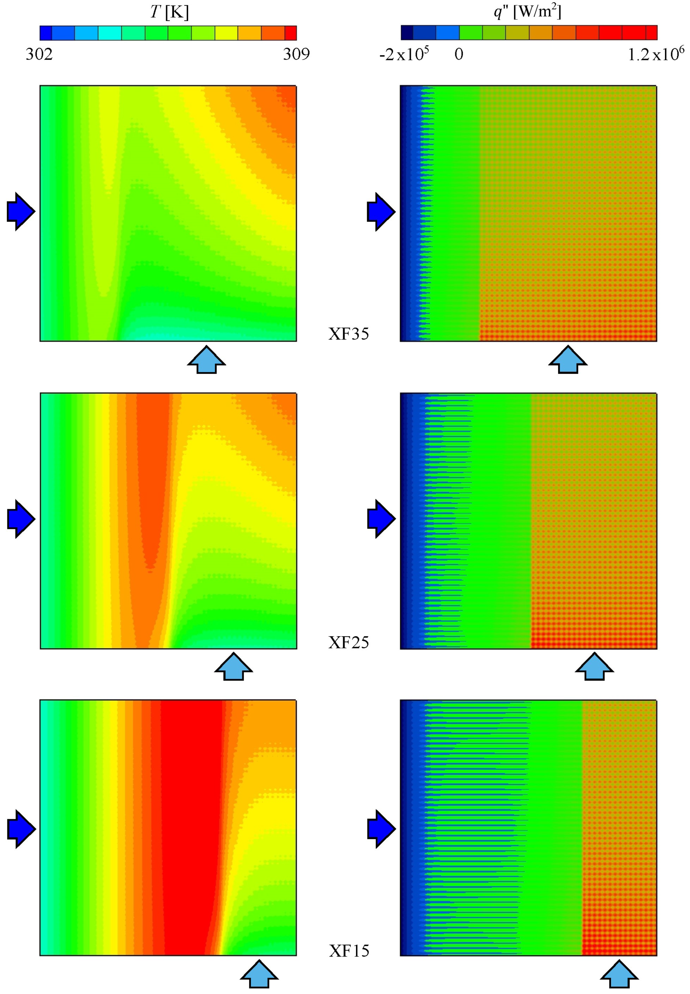
Some additional physical insight can be gained by looking at the temperature and heat flux distributions on the midplane between the bottom and the top layers that are reported in Figure 6 and Figure 7. The strong influence of the microchannel layout on the temperature field inside the DL-MCHSs is apparent. In addition, these figures clearly illustrate which parts of the DL-MCHSs are characterized by negative heat fluxes, i.e., heat fluxes from the top layer to the bottom layer. Figure 6 shows that with the XF configuration the heat flux is positive everywhere, while with the CF arrangement there is a small portion of the midplane, the one near the inlet of the microchannels of the bottom layer, where a negative heat flux occurs. Instead, Figure 7, which concerns the XF35, XF25 and XF15 configurations, i.e., those with a number of microchannels of the top layer smaller than that of the bottom layer, depicts a different scenario. In fact, there are large portions of the midplane where a negative heat flux is present. This can be correlated with the better temperature uniformity that can be achieved when compared to that yielded by the pure cross-flow with since, in the latter case the minimum temperature values of the heated base are lower. Another interesting detail that appears from Figure 6 and Figure 7 is that the positions where the heat flux reaches its highest positive values (red spots in the figures) correspond to the microchannels walls which have a fin-like behavior.
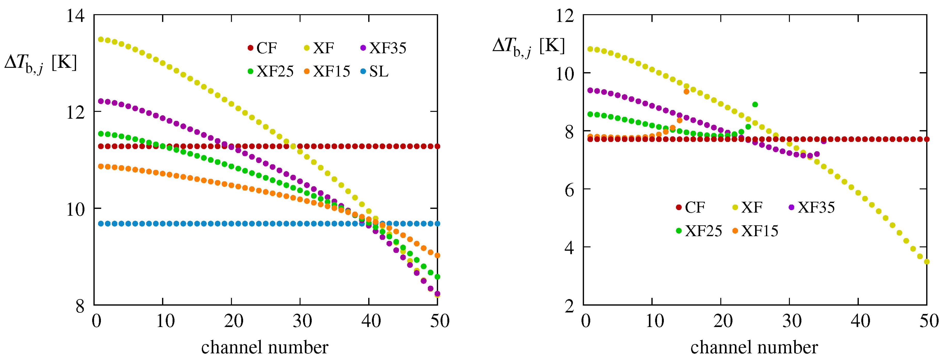
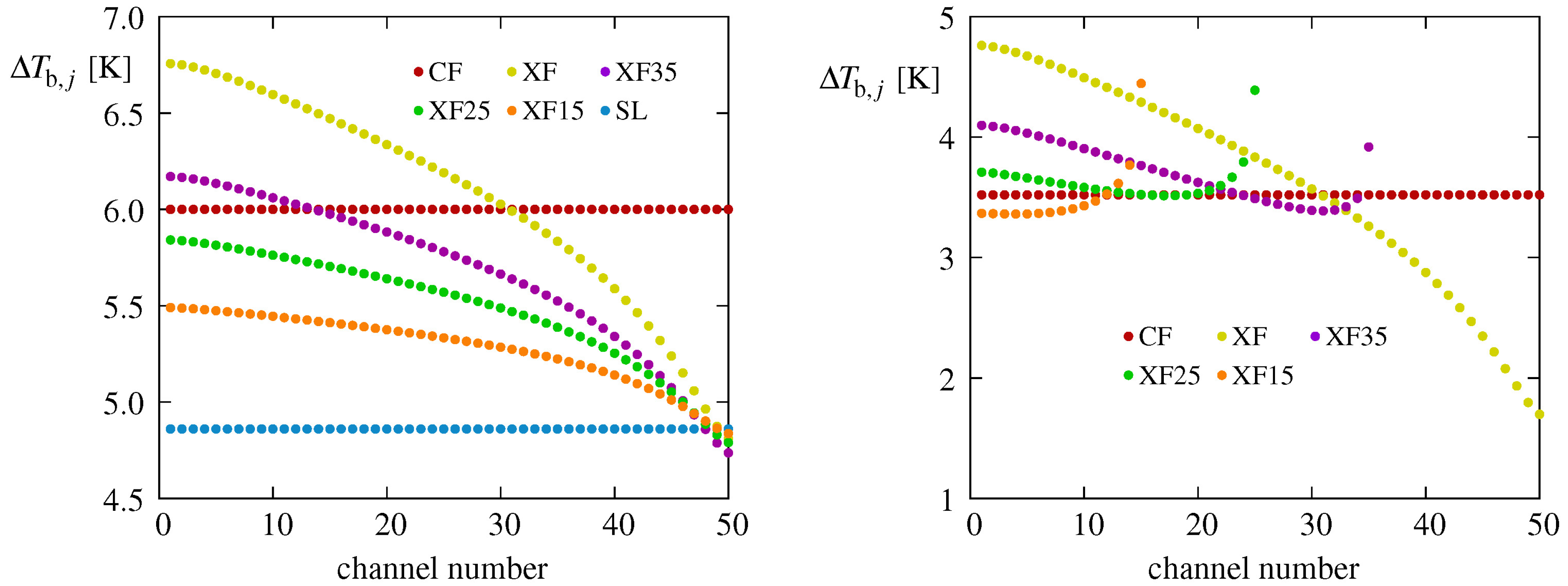
Information on how the flow configuration of a MCHS influences the heat flow rate in each microchannel of one layer can be obtained from Figure 8, Figure 9 and Figure 10, where the differences
between the generic j-th microchannel outlet bulk temperatures and the inlet bulk temperature are reported for the three volume flow rates considered and six of the eight flow arrangements. In each layer of a cross-flow DL-MCHS, the microchannels are numbered starting from the side of the MCHS where the microchannel outlets of the other layer are located. Obviously, with the SL and CF arrangements, are the same in all the microchannels of the same layer, while the maximum variations, both in the bottom and in the top layers, occur with the XF configuration. It must be noticed that the values of pertaining to different DL-MCHSs with cannot be directly compared either among them or to those associated with the configurations where because the microchannel mass flow rates are different even for the same total volume flow rate. However, for each flow arrangement, the figures clearly show which are the microchannels where the heat transfer is more active since higher values of mean more heat removed by that microchannel.
More quantitative comparisons are carried out with reference to (i) the maximum bottom wall temperature change
which is representative of the temperature uniformity of the heated surface, (ii) the total thermal resistance, defined as [15,17,19]
and (iii) the pressure drop in the microchannels. In the above equations, and are the maximum and minimum temperatures on the bottom wall. The computed values of these parameters are shown in Figure 11 for all the test cases considered. The superior thermal performance yielded by the CF configuration is confirmed also with reference to total thermal resistance and pressure drop. However, it is also apparent in Figure 11 that the cross-flow arrangements with yield acceptable temperature uniformities and total thermal resistances. They retain the advantage of the XF configuration of allowing the adoption of just a single header for inlet and a single header for outlet, with a significantly improved thermal behavior, the only downside being a moderately higher pressure drop in the microchannels. It also appears that, with , for each volume flow rate the optimal number of microchannels in the top layer is different and increases for increasing . Finally, the SL MCHS does not prove to be a good choice since it produces the largest of the pressure drops and a mediocre thermal performance.
5. Conclusions
The thermal performance of cross-flow double-layered microchannel heat sinks with an unequal number of microchannels in the two layers was numerically investigated using an in-house finite element method (FEM) procedure. Three values of the coolant volumetric flow rate were considered. The comparison of computed results with those obtained for other more conventional flow configurations shows that, if properly designed, i.e., with a number of microchannels in the top layer smaller than that in the bottom layer, cross-flow double-layered microchannel heat sinks can provide a reasonably good temperature uniformity of the heated base and an acceptable thermal resistance. For a given volume flow rate, they might produce a moderately higher pressure drop in the microchannels compared to other flow arrangements. However, they allow a header design that can be much simpler than that needed with the counter-flow configuration, which has better thermal behavior, but requires two inlets and two outlets to circulate the coolant.
Finally, the present analysis was carried out based on the simplifying assumption of a uniform microchannel inlet velocity in both layers of the microchannel heat sinks (MCHS). However, maldistribution due to poor header design often plagues actual microchannel flows. Previously published results showed that while flow maldistribution always negatively affects the performance of counter-flow double-layered microchannel heat sinks, in some cases, it may turn out to be beneficial for the thermal behavior of cross-flow double-layered microchannel, thus allowing a further reduction of the performance gap between the two flow configurations.
Author Contributions
The two authors (C.N. and S.S.) have contributed equally to this work. All authors have read and agreed to the published version of the manuscript.
Funding
The support of the MIUR through the PRIN Project 2017F7KZWS_005 on this research is gratefully acknowledged.
Conflicts of Interest
The authors declare no conflict of interest.
References
- Tuckerman, D.B.; Peas, R.F.W. High-performance heat sinking for VLSI. IEEE Electron Device Lett. 1981, 2, 126–129. [Google Scholar] [CrossRef]
- Knight, R.W.; Hall, D.J.; Goodling, J.S.; Jaeger, R.C. Heat sink optimization with application to microchannels. IEEE Trans. Compon. Hybrids Manuf. Technol. 1992, 15, 832–842. [Google Scholar] [CrossRef]
- Biswal, L.; Chakraborty, S.; Som, S.K. Design and optimization of single-phase liquid cooled microchannel heat sink. IEEE Trans. Compon. Packag. Manuf. Technol. 2009, 32, 876–886. [Google Scholar] [CrossRef]
- Li, J.; Peterson, G.P. 3-Dimensional numerical optimization of silicon-based high performance parallel microchannel heat sink with liquid flow. Int. J. Heat Mass Transf. 2007, 50, 2895–2904. [Google Scholar] [CrossRef]
- Kou, H.-S.; Lee, J.-J.; Chen, C.-W. Optimum thermal performance of microchannel heat sink by adjusting channel width and height. Int. Commun. Heat Mass Transf. 2008, 35, 577–582. [Google Scholar] [CrossRef]
- Qu, W.; Mudawar, I. Experimental and numerical study of pressure drop and heat transfer in a single-phase micro-channel heat sink. Int. J. Heat Mass Transf. 2002, 45, 2549–2565. [Google Scholar] [CrossRef]
- Chiu, H.-C.; Jang, J.-H.; Yeh, H.-W.; Wu, M.-S. The heat transfer characteristics of liquid cooling heatsink containing microchannels. Int. J. Heat Mass Transf. 2011, 54, 34–42. [Google Scholar] [CrossRef]
- Ansari, D.; Husain, A.; Kim, K.-Y. Multiobjective optimization of a grooved micro-channel heat sink. IEEE Trans. Compon. Packag. Technol. 2010, 33, 767–776. [Google Scholar] [CrossRef]
- Xia, G.; Ma, D.; Zhai, Y.; Li, Y.; Liu, R.; Du, M. Experimental and numerical study of fluid flow and heat transfer characteristics in microchannel heat sink with complex structure. Energy Convers. Manag. 2015, 105, 848–857. [Google Scholar] [CrossRef]
- Adham, A.M.; Mohd-Ghazali, N.; Ahmad, R. Thermal and hydrodynamic analysis of microchannel heat sinks: A review. Renew. Sustain. Energy Rev. 2013, 21, 614–622. [Google Scholar] [CrossRef]
- Vafai, K.; Zhu, L. Analysis of two-layered micro-channel heat sink concept in electronic cooling. Int. J. Heat Mass Transf. 1999, 42, 2287–2297. [Google Scholar] [CrossRef]
- Wei, X.; Joshi, Y.; Patterson, M.K. Experimental and numerical study of a stacked microchannel heat sink for liquid cooling of microelectronic devices. ASME J. Heat Transf. 2007, 129, 1432–1444. [Google Scholar] [CrossRef]
- Xu, S.; Wu, Y.; Cai, Q.; Yang, L.; Li, Y. Optimization of the thermal performance of multi-layer silicon microchannel heat sinks. Therm. Sci. 2016, 20, 2001–2013. [Google Scholar] [CrossRef]
- Levac, M.L.-J.; Soliman, H.M.; Ormiston, S.J. Three-dimensional analysis of fluid flow and heat transfer in single- and two-layered micro-channel heat sinks. Heat Mass Transf. 2011, 47, 1375–1383. [Google Scholar] [CrossRef]
- Xie, G.; Chen, Z.; Sunden, B.; Zhang, W. Numerical predictions of the flow and thermal performance of water-cooled single-layer and double-layer wavy microchannel heat sinks. Numer. Heat Transf. Part A 2013, 63, 201–225. [Google Scholar] [CrossRef]
- Xie, G.; Chen, Z.; Sunden, B.; Zhang, W. Comparative study of the flow and thermal performance of liquid-cooling parallel-flow and counter-flow double layer wavy microchannel heat sinks. Numer. Heat Transf. Part A 2013, 63, 30–55. [Google Scholar] [CrossRef]
- Hung, T.-C.; Yan, W.-M.; Li, W.-P. Analysis of heat transfer characteristics of double-layered microchannel heat sink. Int. J. Heat Mass Transf. 2012, 55, 3090–3099. [Google Scholar] [CrossRef]
- Hung, T.-C.; Yan, W.-M.; Wang, X.-D.; Huang, Y.-X. Optimal design of geometric parameters of double-layered microchannel heat sinks. Int. J. Heat Mass Transf. 2012, 55, 3262–3272. [Google Scholar] [CrossRef]
- Leng, C.; Wang, X.-D.; Wang, T.-H.; Yan, W.-M. Optimization of thermal resistance and bottom wall temperature uniformity for double-layered microchannel heat sink. Energy Convers. Manag. 2015, 93, 141–150. [Google Scholar] [CrossRef]
- Leng, C.; Wang, X.-D.; Wang, T.-H. An improved design of double-layered microchannel heat sink with truncated top channels. Appl. Therm. Eng. 2015, 79, 54–62. [Google Scholar] [CrossRef]
- Leng, C.; Wang, X.-D.; Wang, T.-H.; Yan, W.-M. Multi-parameter optimization of flow and heat transfer for a novel double-layered microchannel heat sink. Int. J. Heat Mass Transf. 2015, 84, 359–369. [Google Scholar] [CrossRef]
- Kulkarni, K.; Afzal, A.; Kim, K.-Y. Multi-objective optimization of a double-layered microchannel heat sink with temperature-dependent fluid properties. Appl. Therm. Eng. 2016, 99, 262–272. [Google Scholar] [CrossRef]
- Wong, K.-C.; Ang, M.-L. Thermal hydraulic performance of a double-layer microchannel heat sink with channel contraction. Int. Commun. Heat Mass Transf. 2017, 81, 269–275. [Google Scholar] [CrossRef]
- Wu, J.M.; Zhao, J.Y.; Tseng, K.J. Parametric study on the performance of double-layered microchannels heat sink. Energy Convers. Manag. 2014, 80, 550–560. [Google Scholar] [CrossRef]
- Ansari, D.; Kim, K.-Y. Double-layer microchannel heat sinks with transverse flow configurations. ASME J. Heat Transf. 2016, 138, 031005-1–031005-13. [Google Scholar] [CrossRef]
- Ansari, D.; Kim, K.-Y. Performance analysis of double-layer microchannel heat sinks under non-uniform heating conditions with random hotspots. Micromachines 2017, 8, 54. [Google Scholar] [CrossRef]
- Tang, S.; Zhao, Y.; Quan, Z. Multi-objective optimization of double-layered microchannel heat sink based on derivative-free algorithm. Numer. Heat Transf. Part A 2018, 73, 535–552. [Google Scholar] [CrossRef]
- Nonino, C.; Savino, S. Flow Maldistribution Effects on the Temperature Uniformity in Double-Layered Microchannel Heat Sinks. In Proceedings of the ASME 2019 17th International Conference on Nanochannels, Microchannels, and Minichannels, St. John’s, NL, Canada, 23–26 June 2019. [Google Scholar]
- Nonino, C.; Savino, S. Effects of Non-Uniform Flow Distribution In Double-Layered Cross-Flow Microchannel Heat Sinks. In Proceedings of the Second Pacific Rim Thermal Engineering Conference, Maui, HI, USA, 13–17 December 2019. [Google Scholar]
- Shah, R.K.; London, A.L. Laminar Flow Forced Convection in Ducts; Academic Press: New York, NY, USA, 1978. [Google Scholar]
- Nonino, C.; Del Giudice, S.; Comini, G. Laminar forced convection in three-dimensional duct flows. Numer. Heat Transf. 1988, 13, 451–466. [Google Scholar] [CrossRef]
- Nonino, C.; Savino, S.; Del Giudice, S. FEM for the 3-D analysis of conjugate conduction-convection heat transfer in cross-flow micro heat exchangers. Int. J. Numer. Methods Heat Fluid Flow 2015, 25, 1322–1339. [Google Scholar] [CrossRef]
- Nonino, C.; Savino, S. Numerical investigation on the performance of cross-flow micro heat exchangers. Int. J. Numer. Methods Heat Fluid Flow 2016, 26, 745–766. [Google Scholar] [CrossRef]
Figure 1.
Schemes illustrating the eight MCHS configurations considered (dark blue: bottom layer; light blue: top layer).
Figure 1.
Schemes illustrating the eight MCHS configurations considered (dark blue: bottom layer; light blue: top layer).

Figure 2.
Schemes illustrating possible header layouts for counter-flow and cross-flow MCHS.

Figure 3.
Bottom wall temperature distributions for six MCHS configurations and mL/s (dark blue arrow: bottom layer; light blue arrow: top layer).
Figure 3.
Bottom wall temperature distributions for six MCHS configurations and mL/s (dark blue arrow: bottom layer; light blue arrow: top layer).

Figure 4.
Bottom wall temperature distributions for six MCHS configurations and mL/s (dark blue arrow: bottom layer; light blue arrow: top layer).
Figure 4.
Bottom wall temperature distributions for six MCHS configurations and mL/s (dark blue arrow: bottom layer; light blue arrow: top layer).

Figure 5.
Bottom wall temperature distributions for six MCHS configurations and mL/s (dark blue arrow: bottom layer; light blue arrow: top layer).
Figure 5.
Bottom wall temperature distributions for six MCHS configurations and mL/s (dark blue arrow: bottom layer; light blue arrow: top layer).

Figure 6.
Temperature (left) and heat flux (right) distributions on the midplane between the bottom and the top layers in types CF and XF of DL-MCHSs for mL/s (blue: negative heat flux; dark blue arrow: bottom layer; light blue arrow: top layer).
Figure 6.
Temperature (left) and heat flux (right) distributions on the midplane between the bottom and the top layers in types CF and XF of DL-MCHSs for mL/s (blue: negative heat flux; dark blue arrow: bottom layer; light blue arrow: top layer).

Figure 7.
Temperature (left) and heat flux (right) distributions on the midplane between the bottom and the top layers in types XF15, XF25 and XF35 of DL-MCHSs for mL/s (blue: negative heat flux; dark blue arrow: bottom layer; light blue arrow: top layer).
Figure 7.
Temperature (left) and heat flux (right) distributions on the midplane between the bottom and the top layers in types XF15, XF25 and XF35 of DL-MCHSs for mL/s (blue: negative heat flux; dark blue arrow: bottom layer; light blue arrow: top layer).

Figure 8.
Microchannel outlet bulk temperatures in the bottom and top layers for mL/s (left: bottom layer; right: top layer).
Figure 8.
Microchannel outlet bulk temperatures in the bottom and top layers for mL/s (left: bottom layer; right: top layer).

Figure 9.
Microchannel outlet bulk temperatures in the bottom and top layers for mL/s (left: bottom layer; right: top layer).
Figure 9.
Microchannel outlet bulk temperatures in the bottom and top layers for mL/s (left: bottom layer; right: top layer).

Figure 10.
Microchannel outlet bulk temperatures in the bottom and top layers for mL/s (left: bottom layer; right: top layer).
Figure 10.
Microchannel outlet bulk temperatures in the bottom and top layers for mL/s (left: bottom layer; right: top layer).

Figure 11.
Quantitative results: (a) maximum bottom wall temperature change ; (b) total thermal resistance ; (c) pressure drop in the microchannels for all the test cases considered.
Figure 11.
Quantitative results: (a) maximum bottom wall temperature change ; (b) total thermal resistance ; (c) pressure drop in the microchannels for all the test cases considered.

© 2020 by the authors. Licensee MDPI, Basel, Switzerland. This article is an open access article distributed under the terms and conditions of the Creative Commons Attribution (CC BY) license (http://creativecommons.org/licenses/by/4.0/).
Share and Cite
MDPI and ACS Style
Nonino, C.; Savino, S. Temperature Uniformity in Cross-Flow Double-Layered Microchannel Heat Sinks. Fluids 2020, 5, 143. https://0-doi-org.brum.beds.ac.uk/10.3390/fluids5030143
AMA Style
Nonino C, Savino S. Temperature Uniformity in Cross-Flow Double-Layered Microchannel Heat Sinks. Fluids. 2020; 5(3):143. https://0-doi-org.brum.beds.ac.uk/10.3390/fluids5030143
Chicago/Turabian StyleNonino, Carlo, and Stefano Savino. 2020. "Temperature Uniformity in Cross-Flow Double-Layered Microchannel Heat Sinks" Fluids 5, no. 3: 143. https://0-doi-org.brum.beds.ac.uk/10.3390/fluids5030143