
Integration of Fluidic Nozzles in the New Low Emission Dual Fuel Combustion System for MGT Gas Turbines

MAN Energy Solutions SE, 46145 Oberhausen, Germany
*
Author to whom correspondence should be addressed.
Fluids 2021, 6(3), 129; https://0-doi-org.brum.beds.ac.uk/10.3390/fluids6030129
Submission received: 18 February 2021
/
Revised: 15 March 2021
/
Accepted: 18 March 2021
/
Published: 21 March 2021
(This article belongs to the Special Issue Fluidic Oscillators-Devices and Applications)
Abstract
:Fluidic oscillators have proven their capabilities and advantages in terms of the generation of oscillating jets without moving parts for many years, mainly in experimental studies. In this paper, the design, development, and integration of fluidic atomizers into the liquid-fuel system of the dual-fuel low NOX Advanced Can Combustion (ACC) system of the MAN Gas Turbines (MGT) are presented. The two-stage system comprises a pressure-swirl nozzle as a pilot stage and an assembly of four main premixed nozzles, based on fluidic technology. The design and the features of the pilot nozzle are briefly presented, whereas the focus lies on the functionality and layout of the fluidic nozzles. The complete integration, validation, and verification of this innovative liquid-fuel injection unit are presented. The final system features fast fuel-switchovers, low complexity, high reliability, and dry low emissions in liquid-fuel operation.
1. Introduction
Industrial gas turbines in the power range of 5 MW to 20 MW are often used in two settings: either as mechanical drivers of compressors and pumps in the oil and gas industry or for combined heat and power (CHP) scenarios. The main fuel type for gas turbines is natural gas. However, in many parts of the world, the natural gas supply may be interrupted several times in the year. This may disturb the production process or the supply of households with heat in the middle of the winter. Such danger can be avoided by using a backup fuel. In case of a compressor drive application, with a gas extraction site close by, a backup fuel is of crucial importance for restarting the extraction process of natural gas, once the gas exploration has been intermitted. Due to its high availability all over the world and its easy storability, liquid diesel no. 2 is a standard backup fuel for gas turbines.
Since land-based gas turbines are commonly operated with natural gas, the combustion systems are developed and optimized for this fuel in terms of emissions and flexibility. In contrast to that, liquid fuels are widely used in gas turbines for aero applications employing diffusion combustion technology [1,2,3] giving more priority to operation stability than to low emissions. Implementing dual-fuel capabilities to the sensitive dry low NOX combustion systems of land-based gas turbines is demanding in terms of development and testing efforts [4,5,6,7,8,9,10,11,12,13]. While the development of fuel-gas combustion systems benefits from the transferability of atmospheric combustion tests to high pressure conditions [14], liquid-fuel systems cannot substantially profit from comprehensive cost-effective atmospheric testing. This is caused by the pressure sensitivity of liquid fuel combustion due to the dependency of atomization and vaporization on pressure [2]. Additionally, the liquid-fuel injectors are designed for full load fuel flow. Using them at atmospheric conditions and, thus, at fuel flow rates 10 to 15 times smaller, significantly affects the atomization behavior due to the much smaller feed pressure at the nozzle. Scaling the nozzle to atmospheric conditions, on the other hand, is difficult due to the extremely small dimensions resulting from downscaling the geometries and a lack of other proper scaling rules. Moreover, numerical investigations of gas turbine burners and combustion systems by means of computational fluid dynamics (CFD) allow for quick optimization loops in the development process of fuel-gas systems. Even high fidelity simulations are more and more integrated in the design process [15]. However, the two-phase flows associated to liquid-fuel combustion make numerical simulations very expensive in terms of computational power and a lot more difficult to validate experimentally [16].
This paper describes the development and implementation process of a low emission liquid-fuel system for the MAN Energy Solutions industrial gas turbines of the modern MGT family [17,18,19] and its advanced can combustor (ACC) system in the 6–10 MW class. These high efficiency gas turbines are available for CHP and mechanical drive applications. A particular focus is given to the evaluation and characterization of the implemented fluidic nozzles within this specific liquid-combustion solution.
The MGT gas turbines are equipped with six combustor cans featuring single digit NOX emissions for various gaseous fuels. The gas turbine is also available with a dual-fuel option for gas and liquid fuels as backup or main fuel. The liquid-fuel system consists of two separate stages with the main fuel nozzles based on fluidic oscillators. Important to the durability and reliability of the system, this jet oscillation is achieved by an oscillating motion of the emanating jet without any moving parts. Instead, this oscillating motion is generated by the unsteady flow pattern inside the fluidic nozzle [20], as the liquid jet is flipping in a two-dimensional domain from one side to the other of the nozzle. Droplets are formed due to the distinct shear stresses in the moving jet. The use of fluidic oscillators in gas turbines [21] and other energy conversion machines [22] has been considered for several years due to its potential to achieve good mixing [23] and rapid atomization [24]. Additionally, fluidic nozzles have been considered for flow control [25], especially for the performance improvement of airfoils [26], and for the attenuation of acoustic tones excited by flows in cavities [27]. A recent review of studies about available fluidic technology has been published by Ghanami and Farhadi [28]. However, to the knowledge of the authors, up to now these kind of nozzles have never been integrated in an industrial gas turbine combustor.
Two features of the fluidic devices are most important for the present study. Firstly, the rapid atomization of liquid fuel at relatively low supply pressure. This allows for better economics in terms of supply pressure and enables for a good premixing of fuel and air before entering the flame zone, which is of crucial importance for low emissions. Secondly, the improved mixing of the emanating jets from fluidic oscillators and air crossflows as shown by Ostermann et al. [29]. These investigations suggest that the crossflow should have an attacking angle of 90° to the sheet formed by the fluidic oscillators. Detailed investigations of the penetration and mixing of pulsed jets in crossflow have been published by Eroglu and Breidenthal [30], claiming a higher penetration compared to steady jets.
The rest of the paper is organized as follows: first, we describe the combustor design and the design of the pressure swirl atomizer used as a pilot nozzle. Afterwards, the different variants of fluidic nozzles that have been studied and the investigated properties of the atomizers are discussed. Subsequently, the experimental test facilities are presented. Finally, we present measurement results from the high-pressure and engine tests and summarize this study.
2. Dual-Fuel Combustor Design
2.1. Overview of the Combustor Design
In this section, the operating principle and the key features of the MGT advanced can combustor (ACC) are introduced.
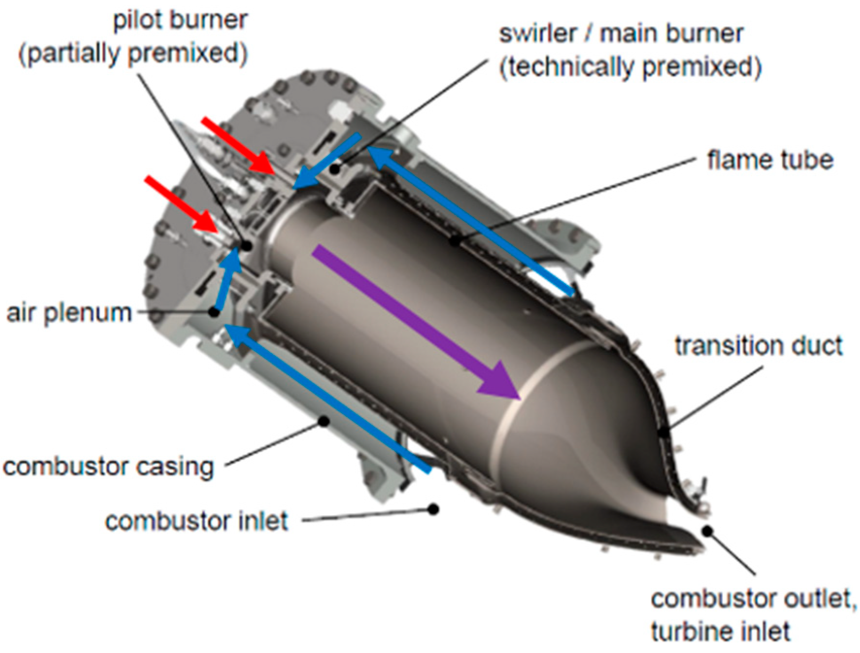
The main hardware parts of one single can are depicted in Figure 1. The blue arrows indicate the air path of the compressor air, which is guided from the compressor outlet into the combustor casing, passing the transition duct and the cylindrical flame tube from the outside. A portion of the compressor air serves as outer cooling air of the transition duct and flame tube walls in order to ensure acceptable material temperatures. High efficiency cooling with a minimum generation of pressure drop is achieved via various cooling methods such as, e.g., effusion cooling and impingement cooling.
Subsequently, the compressor air enters a plenum where it is guided from axial into radial direction and from where it finally enters the radial swirler. At the edges of the swirler vanes, the main fuel-gas injection holes are located to allow for a proper mixing of fuel-gas and air. In fuel-gas operation at baseload, the flame can be considered as almost perfectly premixed.
A gas pilot is used to stabilize the flame at low part load and start-up conditions. The pilot fuel-gas is introduced by means of a number of injection holes at the burner back plate, just upstream of the swirler center (indicated in Figure 1 by the red arrows).
The flame tube is located downstream of the radial swirler. Here, in the region of the area jump between flame tube and swirler, the main flame reaction zone is located. The flame stabilizes in the shear layers of the swirling flow that generates a large recirculation zone going up to the burner back plate. These flow features are the same for dual-fuel and fuel-gas only burners. The transition duct connects the cylindrical flame tube to the annular shape of the turbine inlet section.
In the case of the dual fuel burner, the combustor head is additionally equipped with two types of liquid fuel injectors, each representing a separate fuel stage. An explosion view of a dual-fuel burner is provided in Figure 2. Analog to the fuel gas system, the two-stage concept of the liquid fuel operation concept allows for a stable, safe, and flexible operation of the combustion system from ignition and idle up to full load. The primary stage consists of one central pilot nozzle. In case of ignition and startup, the full amount of liquid fuel is injected via this nozzle. For part load and full load conditions, the share of fuel guided through the pilot nozzle is continuously reduced. However, even at baseload, this pilot nozzle is kept in operation to provide stable operation and to make harsh load jumps to idle possible, the so-called load rejections.
The main stage of the liquid fuel design is also embedded in the swirler back plate. It comprises four decentralized fluidic liquid-fuel nozzles distributed evenly on the circumference at a defined radius. All main stage liquid-fuel nozzles are connected to an X-type fuel divider and thus are collectively controlled.
The liquid-fuel stages are described and discussed in more detail in the following subsections.
2.2. Design of the Pilot Stage
A liquid pilot injector is installed at the centerline of the combustor, flush mounted with the inner combustor wall (swirler back plate); upstream of the flame and downstream of the combustion air swirler. The assembly situation is illustrated in Figure 3a in a schematic cross-sectional view. It is a pressure swirl atomizer with two lines sharing one spill chamber.
In Figure 3b, the two fuel-lines are marked as ‘C’ and ‘D’, respectively. Channel ‘C’ has a central axial swirler and line ‘D’ is equipped with a radial swirler. The radial swirler is formed by tangential drills to the spill chamber. Both swirlers connect the two lines to the same spill chamber. The joint swirling oil flow emanates into the combustion chamber and forms one single conical spray of liquid fuel inside the central recirculation region of the combustor.
The two liquid lines are needed to provide two different spray angles and flow numbers. One is needed for ignition conditions and the other one for normal gas turbine operation. The spray resulting from the first one is qualitatively shown in the picture of Figure 4a and is obtained by operating with line ‘D’ only. Here, a larger cone angle β of approximately 70° with a very fine spray is achieved at relatively low flow rates, representing ignition flow conditions. During ramp up of the gas turbine, the second line ‘C’ is switched on in addition to line ‘D’. This decreases the spray angle β to approximately 44° and increases the flow number significantly. A qualitative picture of the spray angle is given in the picture of Figure 4b. The increased flow number would allow for pilot only operation at maximum pressure conditions of 65 bar(g) up to a certain load level. However, usually the gas turbine is operated at maximum liquid pilot ratios (LPR) of 30–50% even at low part load conditions because this is beneficial in terms of soot emissions. At high load conditions, the pilot fuel flow is minimized in order to optimize NOX emissions. The joint operation mode provides stability to the flame at low part load conditions and avoids any risk of wetting the wall of the combustion chamber thanks to the smaller spray angle.
The mounting position of the central pilot lance is particularly challenging in terms of thermal loading. This is because of the hot combustion products that are forced by the central recirculation zone of the combustor directly towards the nozzle position. This challenge is addressed with special cooling measures. Therefore, compressor air is extracted directly upstream of the main swirler at the burner plenum ‘A’. It is supplied to plenum ‘B’ where it is used to cool the central nozzle and the surrounding plate. This cooling air feeds a small radial air swirler that is illustrated in Figure 3b. Subsequently, the air cools the cap of the nozzle from the inside and emanates from the nozzle with a swirling angle of γ. This angle helps to shield the cap from the hot flow inside the combustor.
Additionally, the cooling air of the cap supports the atomization of the liquid fuel at very small mass flows. This is illustrated in Figure 5, which shows a case without cooling air (Figure 5a) and a case with cooling air (Figure 5b) for very low liquid-fuel mass flows representing the low pilot mass flow at base load conditions. Without cooling air, the small supply pressure is not sufficient for good atomization because velocities in the spill chamber are too small to form a proper cone at the exit. Due to the additional cooling air that interacts with the liquid fuel at the exit of the lance (see Figure 3b), a sufficient atomization and the formation of a proper cone is established. This is qualitatively shown in the picture of Figure 5b.
Prior to full gas turbine testing, the ignition window of the pilot lance has been assessed by means of atmospheric combustion tests. The cone angle and flow number of line ‘D’ has been optimized to achieve a sufficient large ignition window. Additionally, the nozzle has been thermally analyzed and the analytic thermal model has been validated with extensive thermocouple measurements. The temperatures are low enough to ensure high component lifetimes. Moreover, the temperatures in the liquid-fuel channels are sufficiently low to avoid coking of remnants of liquid fuel in the channels when the liquid-fuel supply is stopped and the combustor is operated in fuel-gas mode.
3. Main Stage Injectors Design
3.1. Requirements for the Main Liquid-Fuel Stage
The pilot stage described so far has been designed to enable ignition on liquid fuels, and is very effective in stabilizing the flame from idle up to any load. This very robust combustion behavior originates from the direct injection of the pilot fuel into the reaction zone, creating a very hot diffusion flame at the center of the combustion chamber. This robustness comes at the price of a NOX penalty associated with locally high temperatures.
To enable the overall liquid-fuel system to operate at a globally low emission level, a main liquid stage is integrated into the burner. From idle load of the gas turbine onwards, the majority of the liquid-fuel flow is injected from there. The primary function of the main liquid fuel stage is to provide an injection strategy that will lead to an effective fuel–air mixing at the global and local scales prior to the flame front.
Good mixing quality of the liquid fuel with the incoming air requires a good penetration of the liquid into the air stream to ensure a rather uniform fuel–air ratio at the large scales. Liquid jets, often in the form of plain jets, are thus often employed in liquid fuel systems, due to their high-momentum, penetration capacity and ease of implementation (e.g., [9]). Excessive penetration should, however, be avoided to prevent the risk of burner walls wetting, which could lead to local thermal stresses, or localized reactions, as well as material overheating. To achieve mixing at the small scales, atomization of the liquid stream is required. The generation and distribution of droplets enhances the local fuel placement and further fuel–air uniformity prior to the heat release zone. Additionally, the formation of smaller droplets leads to an increased surface to volume ratio of the liquid, thereby improving the heat transfer to the liquid and its subsequent evaporation. In the case of a liquid jet, the process of atomization is triggered by the shear exerted at the interface between the liquid column and the surrounding airflow. Therefore, high fuel jet velocities and crossflow intensity promote the break-up process and the generation of smaller droplets. The proper design and placement of the main stage injectors is therefore critical to the performance of the liquid fuel combustion system.
3.2. Investigations of Fluidic Oscillators
In order to tackle the requirements presented in the previous section, fluidic oscillators have been adopted to serve as main fuel nozzles. This development has been a joint project by MAN and FDX. FDX conducted the measurements presented in this Section 3.2 about the investigations of fluidic oscillators.
The working principle of these injectors relies on the generation of a two-dimensional, high-frequency oscillating jet as the liquid stream passes through the nozzle, forming a thin liquid sheet as it is discharged in the combustor. Figure 6 visualizes the droplet generation in the spray sheet of the fluidic with an instantaneous high-speed photo in the vicinity of the nozzle exit. The photo reveals that the jet break up happens extremely close to the nozzle exit. This is a consequence of the shear forces introduced by the flipping motion of the jet.
An exemplary mean liquid sheet formed by the oscillating jet is illustrated in Figure 7. There, the intensity of the spray is visualized by post-processing and analyzing the brightness of spray images, indicating the distribution of the density downstream of an injector. In the present case, diesel is used as working medium and injected into a quiescent environment. For the injector analyzed in Figure 7, the liquid jet forms a sheet with an opening angle between approximately 30° and 40°. The fuel dispersion is not perfectly homogeneous across the spray angle, as indicated by the red color in Figure 7. This is particularly observed in the close proximity of the injector nozzle. Ten nozzle diameters downstream of the injector, however, the mass flow in the liquid sheet is more evenly distributed. This initial inhomogeneous distribution can be beneficial for the penetration of the liquid jet into the swirling air. Further downstream, a small deficit of flow in the center is observed due to the turning points of the oscillating jet at the edge of the sheet that feature more flow due to the extended residence time.
The oscillating jet generated at the exit of the nozzle finds its origins in the flow dynamics inside the fluidic oscillators [20]. The internal design promotes a natural and controlled flow instability, which forces the liquid jet to flip between two symmetric states within a two-dimensional plane. This upstream periodic motion translates into a controlled downstream oscillation of the jet. The internal fluid flow instability is promoted by two feedback channels and the Coandă effect. Thus, the unsteadiness does not require moving parts to achieve this downstream flow behavior. The liquid jet emanating from the injector leads to a good penetration of the liquid flow into the airflow while the periodic oscillations of the jet provide a spatial distribution of the fuel over a cycle and an early jet break-up.
The injection velocity, increased by the lateral motion induced by this unsteady motion, leads to high levels of shear stress along the interface of the liquid stream, thereby leading to the rapid formation of small liquid fuel droplets. Exemplary size assessments from a fluidic oscillator tested during the development of the main injectors is provided in Figure 8. The measurement position with respect to the nozzle exit is indicated in Figure 8a. The analyses were conducted 5 cm downstream of the nozzle exit at the center of the diesel spray sheet. The distance has been chosen with respect to the swirler height of the combustor. Since the mass flow rate density differs in flow oscillation direction (see Figure 7) the measurement results depend on the measurement position. However, we expect qualitatively similar results for the center and edge of the spray. A far field microscope has been used for the measurement, covering an area of 4.3 mm times 3.3 mm. Figure 8b illustrates the droplet size distribution in terms of a probability density function (PDF) for a feed pressure of 5 bar(g). The mean droplet size is 102 µm, while the Sauter mean diameter (D32 or SMD) is at 185 µm. The PDF is distributed broadly and the droplets sizes are in the range of 40 µm to 200 µm. Figure 8c shows the PDF for a feed pressure of 10 bar(g) at the center of the spray sheet. Here, the droplets are smaller with a mean droplet size of 92 µm, and a Sauter mean diameter of 148 µm. With increasing pressure, the PDF becomes sharper. This is also valid for a pressure of 15 bar(g) that is depicted in Figure 8d. Here, the mean diameter is almost unchanged with 91 µm compared to 10 bar(g). However, the Sauter mean diameter is significantly smaller with 134 µm.
As mentioned earlier, the atomization quality depends strongly on the momentum of the liquid jet as it is injected, and depends therefore on the fuel mass flow and, at a system level, on the gas turbine relative load. At higher loads, where the fuel flow and the combustor firing temperature are higher, the quality of the droplets becomes more critical to the performance of the combustor. Here, NOx emissions rise exponentially with the flame temperature, which increases the importance of the mixing quality of fuel and air. However, it is not clear whether achieving extremely small droplets is beneficial, since the spray needs to penetrate sufficiently into the air flow to achieve an efficient large-scale spatial mixing. Besides penetration, it is more important for gas turbine combustor applications that a significant atomization is achieved at lower operating pressures already. Figure 9 shows the evolution of the Sauter mean diameter (SMD) of the droplets downstream of the injector as a function of the required feed pressure. The SMD is defined as the diameter of a droplet having the same volume to surface ratio as the entire spray [1], it is commonly used in combustion investigations for the characterization of sprays. The markers in Figure 9 represent the single measurement points obtained at measurement position ‘m’ (see, Figure 8a) and the curve shows a simple correlation based on the square root of the feed pressure of the form
where δ and c denote constants and p the feed pressure of the nozzle, respectively. In this case, δ is 272 µm (bar)−0.5 and c is 63 µm. As expected, the atomization quality increases with increasing nozzle pressure, likely saturating at a SMD level of approximately 100 µm. However, it should be emphasized that these data give only a qualitative insight to the spray characteristics of fluidic atomizers because of the limitation of the conducted droplet measurement study. Nevertheless, it is clear that, as the gas turbine operating load increases and thereby the fuel flow and feed pressure, the atomization quality of the main stage increases, too.
Fluidic oscillators are thus very robust approaches to generating high-velocity liquid fuel sheets, and therefore feature efficient liquid-fuel atomizers. Their use in liquid-fuel combustion systems has long been considered. The actual integration into the MGT liquid fuel combustion hardware is, to the best of the authors’ knowledge, the first actual implementation of fluidic nozzles in the combustion chamber of an industrial product.
Practically, four single nozzles are used for the main stage of the current liquid-fuel combustion system. In order to maximize the evaporation and mixing time of the main liquid-fuel, these injectors are located in the burner just downstream of the vanes of the radial swirler, as depicted in Figure 3a. An X-type fuel divider is used to distribute the fuel to the four injectors. In this way, a minimal number of screw connections are required for the assembly of the main stage parts, therefore reducing the risk of fuel leakage.
3.3. Integration of the Fluidic Injectors in the Main Stage of the Combustor
The integration of the fluidic nozzles into the combustion chamber brings additional complexity on the design and utilization of the injectors: The impact of the surrounding airflow on the injection characteristics and the influence of the spray-to-spray proximity needs to be assessed.
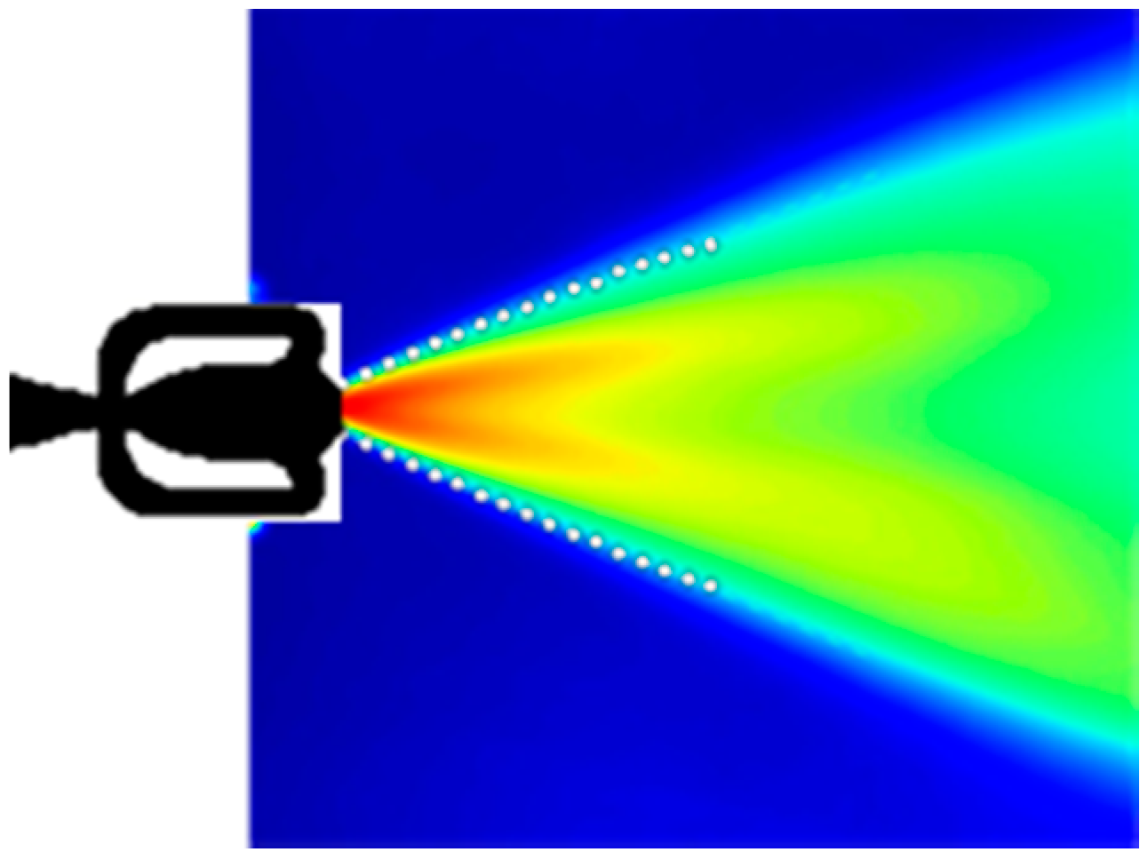
As already indicated in Figure 3a, Figure 6 and Figure 7, a single fluidic injector generates a sheet of liquid spray forming an opening angle Ψ. Since the injectors are flush mounted, directly downstream of the vanes, the airflow, emanating from the swirler vanes, directly affect the liquid-fuel spray as it is discharged in the burner. The interaction between a gaseous jet emanating from a fluidic injector and air crossflows has been investigated, for instance, by Ostermann et al. [31]. In their study, the oscillation plane is oriented perpendicularly to the crossflow, and they showed that the coherent structures generated by the interaction of the crossflow and the fluidic sheet is significantly different from that of a steady jet. In another recent study of the same researchers [29], the effects of the orientation of the fluidic relative to the crossflow has been investigated for a specific fluidic operating with gaseous fluids. Ostermann et al. claim that the fluidic jet exhibits flow structures similar to a steady jet if the fluidic is oscillating in line with the crossflow direction. During the development of the combustion system presented here, two different orientations of the nozzle sheets were tested in the high-pressure tests. Figure 10 illustrates the two different orientations of the spray sheet with respect to the swirling crossflow. This figure shows the CFD calculated steady flow field in the main air swirler. Additionally, a sheet that is perpendicular to the crossflow emanating from the swirler vanes is indicated with the letter ξ1. Moreover, an oscillation that happens in line with the local flow path is marked with the letter ξ2. In the latter case, the nozzle was tangentially aligned to the specific circle at the mounting position, while in the former case, the oscillation sheet was oriented perpendicularly to the jet emanating from the swirler channel. As described in a later section in detail, a perpendicular orientation is found to be significantly more advantageous to the combustor performance in terms of NOX emissions. This is attributed to the improved mixing of spray and combustion air.
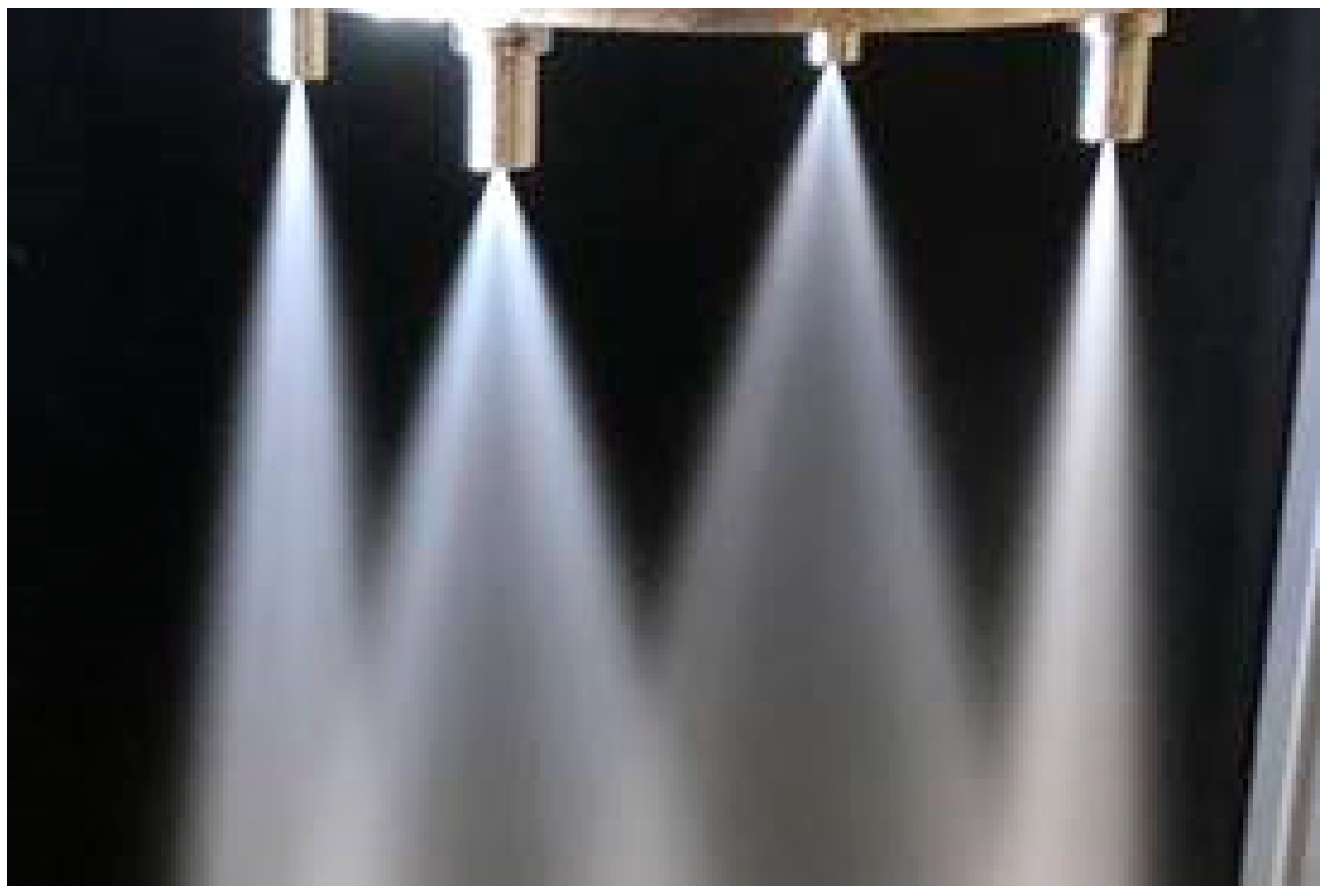
The integration of the four nozzles in the single main stage also carries the uncertainty of the potential interaction between neighboring sprays and the fuel distribution across injectors from the X-divider. An imaging of the very fine spray obtained with water flowing of the complete main stage assembly into quiescent air is provided in Figure 11. The water flow rate is representative of base load operation of the gas turbine. Each nozzle forms a thin sheet of fine spray, exhibiting a homogeneity and spray characteristics similar to those observed during single nozzle flow tests. Furthermore, it can be seen from the flow test of the assembly in quiescent air that, over a distance larger than the swirler height, there is no spatial spray-to-spray interaction between the four single spray sheets.
3.4. Main Stages Nozzles without Liquid Fuel Flow
Most dual-fuel gas turbines are mainly operated on gaseous fuels and switchover to a backup liquid fuel operation is seldom performed. One of the major challenges in the design and operation of a dual-fuel system for gas turbine combustors is to prevent coking of the nozzles while those are not in liquid fuel operation. Coke deposits can obstruct partially or completely the passages for the oil flow, leading to a fuel flow imbalance across the injectors of a can and between the different cans of the turbine. Consequently, an increase in pollutant formation, an increase in fuel oil pressure requirements beyond the oil pump capacity, and an overall lack of reliability and performance of the turbine can be expected. Coking can be attributed to different formation mechanisms, as described for instance in Brandauer et al. [32] as well as Chin and Lefebvre [33]. The coking risk particularly relevant to gas turbine conditions manifests itself after switch-off of the liquid fuel flow. Residual films of liquid fuel remain within the passages and channels of the liquid fuel system. The injectors, integrated within the burner, reach temperatures approaching the compressor exit temperature. Furthermore, after shutting down the liquid fuel flow, hot air encounters the liquid films, leading to the quick coke formation reaction between the liquid fuel and the oxygen of the air.
As a part of the design and integration of the nozzles in the dual-fuel system, a nozzle purging and cooling strategy is required to avoid coking risks. Several such strategies were tested during simplified, atmospheric lab tests. To carry the tests, each test nozzle was flowed with diesel no.2 and the corresponding flow capacity was recorded. Following this first step, a specific purge strategy was conducted, followed by the placement of the test nozzle in an oven running at temperatures simulating the compressor exit conditions. The flow number was measured again at the end of these steps, to assess any decrease in flow capacity, which would reveal internal coking. These cycles were repeated several times for each purge strategy, and the main outcome is provided in Table 1. Five-second pulses of air or water, intended to flush out any residual oil from the main stage, did not eliminate the coking risk of the nozzles. Even complex transient purging strategies were unsuccessful, and coking occurred after 30 to 40 test cycles. It was found, however, that a continuous purge of cooled compressor air in the fuel lines could successfully eliminate the coking risk. This approach was thus adopted for the engine operation, and its functionality was verified during extensive full engine tests.
4. Validation
4.1. Experimental Facilities
It has many advantages to conduct single can high-pressure tests at full power before using components at full engine tests. Components can be extensively tested without compromising effects from other gas turbine components. The impact of different environmental boundary conditions like ambient temperature and altitude on the compressor exit conditions and, thus, the combustor inlet conditions can be conveniently simulated. The tests were conducted at the facilities of the DLR Institute of Propulsion Technology in Cologne where inlet air mass flow, temperature, and pressure can be adjusted separately in wide ranges without significant restrictions. The serial gas turbine combustor components can be tested without special adaption. Custom MAN designs are used for the connection of the single can to the DLR inlet and exhaust interfaces.
The test-rig setup is illustrated in Figure 12. The flow enters the test rig through a circular uncooled inlet connector (1). Subsequently, the flow enters a simulation of the compressor plenum (2) that features one sixth of the volume of the compressor discharge plenum of the gas turbine and is connected to the combustor casing (3). During high-pressure testing, multiple Kistler 6021 high temperature dynamic pressure sensors were mounted at the combustor monitoring possible pressure fluctuations in the combustor. A reduced number of the same sensor-type are applied for full engine testing and continuous monitoring in customer installations. However, no pressure pulsations or thermoacoustic instabilities have been observed for the final dual-fuel combustion system neither in the high-pressure tests nor in the final engine tests.
The inlet guide vanes of the turbine are simulated with a so-called vane simulation (4). This water-cooled part is located downstream of the transition duct (see Figure 1). Removable circular blockages are located in the hot-gas path to accelerate the flow similarly to the real turbine. The exhaust pipe (5) at the end of the test rig conditions the exhaust flow to accurately measure emissions with emission probes (6). The length of the tube is designed to achieve almost perfectly mixed exhaust gases at the probe position. During the tests, the exhaust gas has been analyzed for NOX, CO, O2, UHC emissions, as well as soot particles. Several valves have been used to switch separately on and off primary 1 and 2, as well as secondary flow, and purging. The valves are mounted to a valve terminal (7). Real engine purging conditions have been simulated in the test-rig.
Recently, a new gas turbine test-bed for full engine tests has been installed at the MAN gas turbine center in Oberhausen. The main challenge is the integration of cold-end-drive and hot-end-drive units, and different power ratings, into one test-bed. The test bed is designed to serve for high frequency full engine acceptance tests caused by serial production and detailed development engine tests.
Depending on the type of gas turbine, a generator is coupled to the gas turbine using one of three different load gears. The gas turbines generate electrical power that is dissipated to heat, which is currently dumped in cooling towers. In a planned extension of the test stand, the heat will be fed into the district heating network of Oberhausen. Figure 13 shows a photograph of an MGT6000 installed at the described new test stand. Flexible ducts are used to connect the exhaust and intake of the gas turbine.
For the presented study, an especially equipped prototype gas turbine for testing purposes has been used. This gas turbine is heavily instrumented and can deliver many supplementary data, like additional thermocouples and differential pressure measurements. However, for the sake of robustness and comparability between the tests, the gas turbine is operated without the newest efficiency upgrades. Due to the efficiency penalty of the validation unit, slightly higher NOX emissions are generated due to the higher turbine inlet temperature compared to customer engines. Hence, the engine emissions presented in this study show a worst-case scenario while the high-pressure tests correspond to a customer engine behavior.
4.2. High Pressure Tests of Different Fluidic Nozzles as Main Stage
High pressure tests were conducted to optimize the spray angle, flow number and injection position of the fluidic nozzles in terms of emissions and flame stability. Fluidic nozzles with three different opening angles have been designed, manufactured, and tested: 30° (in the following named variant V30), 50° (V50), and 60° (V60). In addition, a variant V50* of the 50° spray angle nozzle has been tested, which features a larger flow number and, thus, effective area Aeff (Aeff(V50*) = 1.36Aeff(V50)). The motivation for the larger spray angles was the hypothesis that a better fuel distribution in the flow could be achieved, whereas the variation of the flow number could influence the penetration of the droplets into the flow. Each of these hardware variants has been tested at the same simulated engine conditions at the high-pressure test rig at the DLR in Cologne.
A comparison between the four different main liquid-fuel nozzle designs in terms of NOX emissions is depicted in Figure 14. NOX emissions are normalized by the NOX emission of the variant V30 at baseload. The tests were conducted without any additional pilot flow, in order to evaluate and quantify the degree of mixing quality achieved by each decentralized fluidics injector design, independently of the central injector. From part load up to 90% relative engine power, a larger spray angle has a clear beneficial impact on the NOX emissions. However, the benefit is decreasing with increasing power and, thus, fuel mass flow and injection pressure. Additionally, the compressor air pressure, air temperature, and firing temperature increases with relative load. Due to the limited available information, only a hypothesis can be presented as reasoning. At lower loads, the flame is operated at significantly lower flame temperatures, which causes the flame to stabilize further downstream compared to baseload conditions. This increases the mixing time of the liquid fuel. Thus, a better distribution of the relatively large droplets is beneficial at part load. While the V30 exhibits a steady exponential increase of the NOX emissions with respect to the relative power, the larger spray angle variants show an excessive rise of NOX emissions for relative powers larger than 90%. It is assumed that the fuel penetration of all variants but V30 is not sufficient at higher loads. This causes locally fuel-rich areas and helps to stabilize the flame upstream, thereby shortening the mixing time significantly. As a result, the NOX emissions rise disproportionately to the increase of the global flame temperature. This reasoning is further supported by the following observations.
Two phenomena have been recorded, which underline this finding: A significantly increased dynamic pressure amplitude and a large fluctuation of the NOX emissions. Figure 15a shows the normalized acoustic pressure amplitude. Up to a relative load of 70%, the acoustic pressure fluctuations are mostly independent of the spray-opening angle. For an increasing engine power, the amplitude significantly rises for larger spray angles compared to the 30° variant, leading to a threefold increase of the 60° variant at baseload. Note that these amplitudes refer to the low frequency regime and are associated to broadband fluctuation. The time traces of the NOX emission probe are shown in Figure 15a. Under steady operation conditions at base load, the NOx emissions fluctuate by about +/−50% for the 60° spray opening angle, whereas the variation of the NOX emissions at baseload for the 30° variant lower than <5%. For injector V60, the general level of the NOX emissions points to a diffusion combustion regime (Figure 14), while the broadband dynamic pressure fluctuations and the large scale NOX emissions fluctuations indicate an unsteady switch between the premixed and diffusion combustion regime. It is not uncommon for liquid fuel flames to exhibit different stabilization modes and regimes for the same operating conditions [34]. This is triggered by the position of the vaporization of the liquid droplets.
The change in the mean flame position is tracked by thermocouples installed along the circumference at various axial positions along the hot-gas path. Figure 16 depicts for each of the main liquid-fuel nozzle variants the normalized average value of circumferentially distributed thermocouple measurements at two axial locations: TA at the mixing tube just upstream of the flame tube inlet (Figure 16a) and TB further downstream at about two thirds of the length of the flame tube (Figure 16b). The temperatures are normalized by the value of V30 at baseload conditions. On the upstream side of the flame tube, the temperature for wider spray opening angles increases significantly for relative engine loads higher than 90% compared to an opening angle of 30°. The opposite is found further downstream in the flame tube. Here, the flame does not penetrate as deep into the flame tube for larger spray opening angles.
In the last three figures, we also showed the respective results for a liquid-fuel main nozzle variant V50* which has an opening angle of 50° but an effective area that is 36% larger compared to the V50 variant. The performance of this nozzle in terms of NOX emissions is apparently in between the V50 variant and the V60 variant. The reduced pressure drop across the nozzle seems to cause a lower penetration depth of the injected liquid-fuel (see Figure 16) and thus has a similar effect as the widening of the spray-opening angle at constant pressure drop. The SMD of the V50* at baseload is comparable to the SMD of the other variants. At high pressures, the SMD is already in the saturation zone depicted in Figure 9. Consequently, the V50* does not strongly affect vaporization time of the liquid-fuel droplets; however, its smaller penetration depth due to the lower momentum of the liquid-fuel leads especially at baseload to a less stable combustion behavior and a tendency towards higher NOx emissions compared to V50.
The fluidic atomizer V30, with 30° spray angle, is used for the investigations presented hereafter. Even though it leads to higher NOX emissions at part load than the other injector variants (V50, V50*, and V60), these emissions are still well within the intended emission guarantees of the engine. Furthermore, integrating the V30 injectors for the main injection ensures a very stable combustor operation with the best emissions at baseload.
Another parameter that has been varied and tested in the high-pressure campaign is the orientation of the spray sheet with respect to the airflow (see Section 3.3, Figure 10). The orientation ξ1, where the spray sheet is perpendicularly aligned with respect to the exit velocity vector of the swirler, provides clearly better NOX emissions compared to a tangential arrangement (orientation ξ2). This is shown in Figure 17 by means of the normalized NOX emissions with respect to the relative engine power. The advantageous behavior is based on a significantly better mixing of the liquid-fuel with the air emanating from the swirler. Here, the air hits the spray with a maximum area of attack, which causes the droplets to be surrounded by air with a minimized risk of an accumulation of droplets. The latter would lead to locally rich streaks in the reaction zone causing higher overall NOX emissions. The small level dynamic pressure amplitudes are not affected by the spray sheet orientation.
An additional design parameter that has been evaluated in the high-pressure tests is the radial position of the four fluidic atomizers with respect to the combustor axis. This diameter is limited with its maximum by the inner diameter of the swirler and with its minimum by the space required for the incorporation of the central liquid-fuel nozzle and the fuel-gas pilot. Furthermore, a too large diameter boosts the risk of wetting the inner walls of the mixing section and a small diameter restricts the premixing time. Two variants have been tested, one radial position r1 and a radial position r2, with r1 < r2. Neither positions caused any wetting of the wall with liquid-fuel. Figure 18 reveals that the larger radial position has two advantageous effects. First, the NOX emissions are considerably reduced especially at high load levels. Second, there is also a clear reduction in the broadband dynamic pressure fluctuations observed for higher loads. The main advantage of position r2 is the increased mixing and vaporization time with, at the same time, a comparable penetration into the airflow.
4.3. Performance of Serial Liquid-Fuel System at Engine Test
In the previous section, we discussed selected design variations of fluidic nozzles that have been experimentally evaluated in single can full load test. This section presents the performance of the complete system in the full engine gas turbine test.
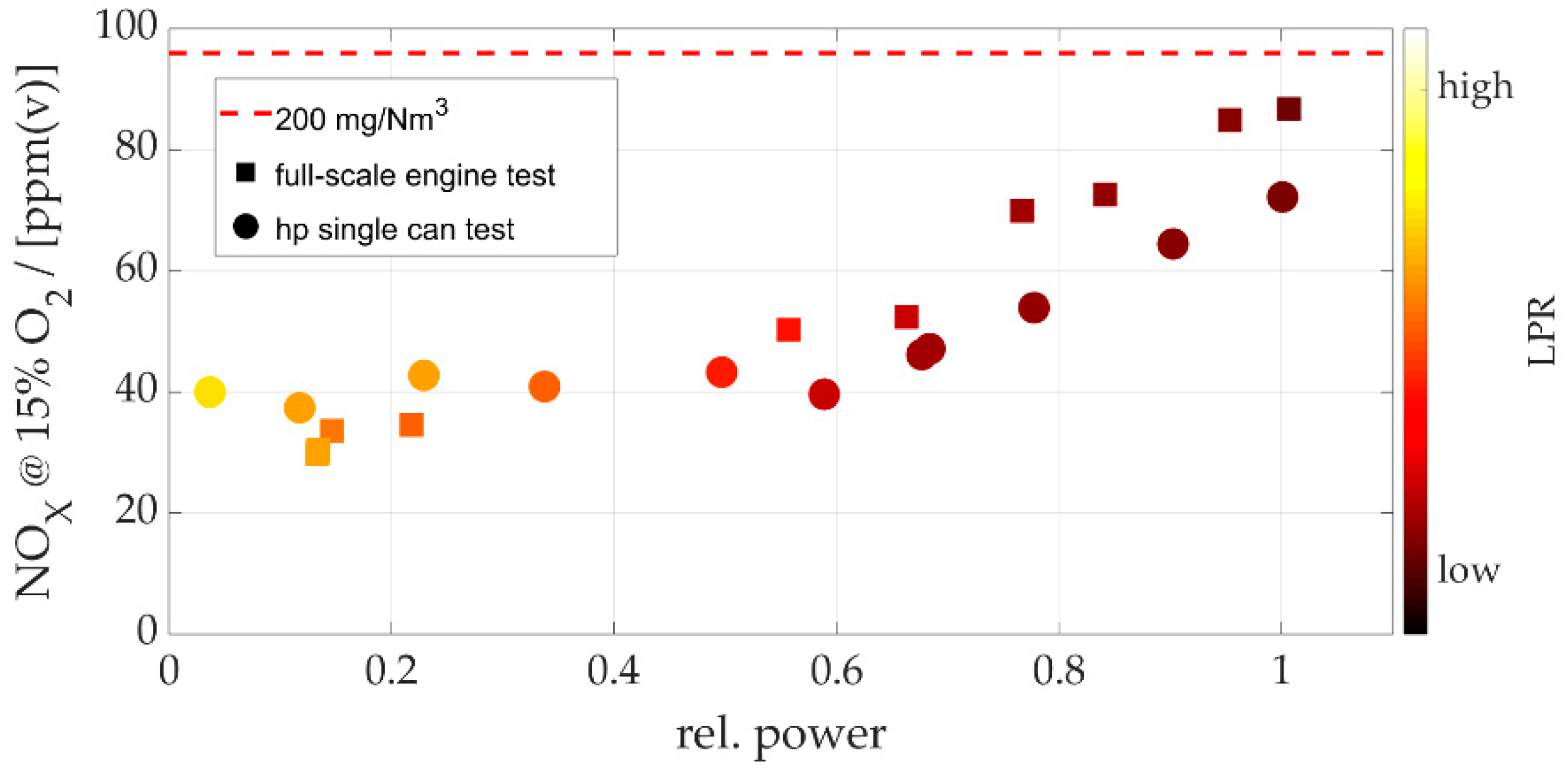
The NOX emissions of the final variant, normalized to 15% O2, are depicted in of Figure 19 with respect to the relative engine power. Here, the high-pressure single-can test results are compared to full-scale engine test data obtained at the test bed in Oberhausen. From part load conditions of 50% up to baseload, the constant offset between the full-scale validation test and the high-pressure single-can test is due to the different turbine inlet temperatures reached in each test. The fully instrumented test engine is a prototype rating, which does not deliver optimal performances in terms of efficiency, and runs at relatively high turbine inlet temperatures. Gas turbines of the MGT family from serial production do not show significant variations in turbine inlet temperatures at given power outputs, in all cases lower than that of the prototype test engine. Therefore, the high-pressure combustion tests have always been very representative of the operating conditions at the customer’s sites. Against this background, the agreement of the different test results in Figure 19 is very good. Due to operational considerations, the main stage is never operated without pilot fuel. This is indicated by the coloring in Figure 19, which denotes the liquid pilot ratio. This is the share of pilot liquid-fuel with respect to the overall fuel-mass flow. The liquid pilot ratio is decreased as the load is increased to achieve better emissions. From idle to 50% load, the NOX emissions are at an almost constant level of 40 ppm and increase continuously up to baseload (Figure 19). Emissions of less than 75 ppm are representative of a serial MGT engine operated at baseload conditions, as simulated in the high-pressure tests. The emissions of the full-scale prototype engine shown here can be considered as a worst case scenario of a degenerated and less efficient engine; however, even in this case, the NOX emission remain well below 90 ppm.
In addition to NOx, also CO emissions, UHC emissions, as well as soot particle densities have been assessed. However, they are only of concern at part load conditions and further down to idle. There, the LPR is relatively high, which means that the liquid-fuel mass flow through the main stage nozzles is comparably low. Hence, these conditions are rather beyond the most interesting design optimum of the fluidics injectors and consequently the results are not shown in this study. Overall, the CO and UHC emissions correspond to a typical partially premixed gas turbine flame and, in particular, the soot emission levels are well within legal restrictions. The stable behavior of the fluidics oscillators also at low mass flows contributes to these good results.
In addition to the combustor and gas turbine performance implications, the impact of the integration of the dual fuel combustion system on the combustor parts and downstream components has been examined during the validation process. Extensive thermocouple instrumentation of the combustor parts for high-pressure and full engine testing. We did not detect any significant difference in axial or azimuthal temperature distribution between fuel-gas and liquid fuel operation.
A highly important feature of a dual-fuel gas turbine is the fast switch from fuel-gas to liquid fuel (and vice versa) during operation at any load. In order to achieve a smooth and fast switchover between fuel-gas and liquid-fuel, the combustion system, and its periphery have to interact in an accurately and well-defined sequence. Such a transient event like a fuel switchover benefits strongly from a key feature of fluidic nozzles: a good atomization even at relatively low fuel mass flows. Fluidic atomizers only need little assistance of the pilot stage to maintain a stable.
Fuel switchovers have been tested, evaluated, and optimized extensively at the MAN full-scale gas turbine test-bed in Oberhausen. Such a switchover can be conducted at any load less than <90% and within a time span of <60 s. Since the realization of such a complex procedure depends much on the fuel skid and the corresponding fuel pumps, for proper validation purposes, the hardware employed at the test bed is identical to what can be found within a customer gas turbine package.
When the purging of the liquid-fuel lines is operated, the gas turbine is in normal fuel-gas mode and delivers the same performance as a MGT gas turbine with a single fuel-gas combustion system. It has been verified that the emissions, as well as the dynamic pressure amplitudes, are not affected by the dual-fuel equipment.
5. Summary and Conclusions
For islands without natural gas supply and for industrial applications with stringent requirements for uninterrupted power and heat supply, gas turbines with liquid-fuel as backup or primary fuel are a viable option. Integrating a low emission liquid fuel system into an existing dry low NOX fuel-gas combustion system is challenging. This paper presents our efforts for the design and integration of the liquid fuel system with a special focus on the development of fluidic atomizers.
We gave a brief overview of the liquid pilot system that has two liquid stages and one stage of swirling shielding air. The centrally placed nozzle features different flow numbers and spray angles, which can be controlled with the two liquid feed lines. The focus of this study is the integration of four fluidic nozzles in the main liquid stage. We presented our approach for the design and integration of the fluidic nozzles and discussed data representing mass flow distribution, orientation of the nozzle, and droplet size distribution. Subsequently, we analyzed high-pressure results for different spray sheet angles and flow numbers. It was found that larger spray angles have some benefits at lower loads, however, at higher air and fuel mass flows smaller angles show much better results in terms of flame stabilization and NOX emissions. The data indicate that the flame stabilization is altered for higher angles at base load conditions. Additionally, our data indicates that, for the specific system investigated, a perpendicular orientation of the spray sheet to the crossflow improves fuel–air mixing. Finally, emission measurements of the high-pressure tests and the full engine validation tests were compared and showed very good agreement.
The final industrialized design of the dual-fuel combustor has proven to be very robust, stable, with competitive dry-low NOX emissions and very fast fuel switchover times. Moreover, with the current central liquid pilot nozzle design, the gas turbine features a start-up on liquid fuel.
To the knowledge of the authors, fluidic nozzles are integrated for the first time in an industrial gas turbine combustor. They have shown great potential for robust and fine atomization starting at low supply pressures. The formation of a fine sheet and the interaction with the swirling crossflow air has great potential for further improved premixing and good flexibility in terms of flame stabilization. Still, work will be conducted to improve the combustion performance further.
Author Contributions
Conceptualization, B.Ć.; methodology, B.Ć.; validation, D.W. and F.G.; investigation, B.Ć. and D.W.; data curation, D.W.; writing—original draft preparation, B.Ć., D.W., and F.G.; writing—review and editing, B.Ć., D.W., and F.G.; visualization, B.Ć., D.W., and F.G.; project administration, B.Ć.; All authors have read and agreed to the published version of the manuscript.
Funding
The work has been supported by the German ministry of economy and technology under grant number 03ET7070L.
Acknowledgments
This work has been conducted as a part of the joint research program COOREFLEX-turbo in the frame of AG Turbo. We thank FDX Fluid Dynamix for the joint development of the OsciJet fluidic nozzles. We thank Roman Proebster for his great personal dedication to the presented development.
Conflicts of Interest
The authors are employed by MAN Energy Solutions SE. The presented study has been funded by MAN Energy Solutions SE.
References
- Lefebvre, A.H.; Ballal, D.R. Gas Turbine Combustion; CRC Press: Boca Raton, FL, USA, 2010. [Google Scholar]
- Lefebvre, A.H.; McDonell, V.G. Atomization and Sprays; CRC Press: Boca Raton, FL, USA, 2017; ISBN 9781498736268. [Google Scholar]
- Liu, Y.; Sun, X.; Sethi, V.; Nalianda, D.; Li, Y.G.; Wang, L. Review of modern low emissions combustion technologies for aero gas turbine engines. Prog. Aerosp. Sci. 2017, 94, 12–45. [Google Scholar] [CrossRef] [Green Version]
- Lindman, O.; Andersson, M.; Persson, M.; Munktell, E. Development of a liquid fuel combustion system for SGT-750. In Proceedings of the ASME Turbo Expo, Düsseldorf, Germany, 16–20 June 2014; Volume 4A. [Google Scholar]
- Zucca, A.; Khayrulin, S.; Vyazemskaya, N.; Shershnyov, B.; Myers, G. Development of a liquid fuel system for GE MS5002E gas turbine: Rig test validation of the combustor performance. In Proceedings of the ASME Turbo Expo, Düsseldorf, Germany, 16–20 June 2014. [Google Scholar]
- Zucca, A.; Asti, A.; Evulet, A.; Khayrulin, S.; Shershnyov, B.; Myers, G. Development of a simplified back-up liquid fuel system for a heavy duty industrial gas turbine. In Proceedings of the ASME Turbo Expo, Copenhagen, Denmark, 11–15 June 2012. [Google Scholar]
- Taylor, P.; McMILLAN, R.; Baker, D. Dual fuel DLE typhoon commercial operating experience and improvement upgrades. In Proceedings of the ASME Turbo Expo, Munich, Germany, 8–11 May 2000; Volume 2. [Google Scholar]
- Algner, M.; Engelbrecht, E.G.; Eroglu, A.; Hellat, J.; Syed, K.J. Development of an oil injection system optimised to the abb double cone burner. In Proceedings of the ASME Turbo Expo, Indianapolis, IN, USA, 7–10 June 1999. [Google Scholar]
- Steinbach, C.; Ruck, T.; Lloyd, J.; Jansohn, P.; Döbbeling, K.; Sattelmayer, T.; Strand, T. ABB’s advanced EV burner-A dual fuel dry low NOx burner for stationary gas turbines. In Proceedings of the ASME Turbo Expo, Stockholm, Sweden, 2–5 June 1998; Volume 3. [Google Scholar]
- Alkabie, H.; McMillan, R.; Noden, R.; Morris, C. Dual fuel dry low emissions (DLE) combustion system for the ABB ALSTOM POWER 13,4 MW cyclone gas turbine. In Proceedings of the ASME Turbo Expo, Munich, Germany, 8–11 May 2000; Volume 2. [Google Scholar]
- Røkke, P.E.; Hustad, J.E.; Røkke, N.A.; Svendsgaard, O.B. Technology update on gas turbine dual fuel, dry low emission combustion systems. In Turbo Expo: Power for Land, Sea, and Air; International Gas Turbine Institute, Turbo Expo (Publication) IGTI: Prague, Czech Republic, 2003. [Google Scholar]
- Lauer, G.; Meisl, J.; Belting, C.; Hoffmann, S. Further development of low-emissions oil combustion in the Vx4.3A hybrid burner. VGB PowerTech 2002, 82, 51–55. [Google Scholar]
- Cramb, D.J.; McMillan, R. Tempest dual fuel DLE development and commercial operating experience and ultra low NOx gas operation. In Proceedings of the ASME Turbo Expo, New Orleans, LA, USA, 4–7 June 2001; Volume 2, pp. 1–7. [Google Scholar]
- Ciani, A.; Eroglu, A.; Güthe, F.; Paikert, B. Full-scale atmospheric tests of sequential combustion. In Proceedings of the ASME Turbo Expo, Glasgow, UK, 14–18 June 2010; Volume 2, pp. 759–768. [Google Scholar]
- Gicquel, L.Y.M.; Staffelbach, G.; Poinsot, T. Large Eddy Simulations of gaseous flames in gas turbine combustion chambers. Prog. Energy Combust. Sci. 2012, 38, 782–817. [Google Scholar] [CrossRef] [Green Version]
- Westbrook, C.K.; Mizobuchi, Y.; Poinsot, T.J.; Smith, P.J.; Warnatz, J. Computational combustion. Proc. Combust. Inst. 2005, 30, 125–157. [Google Scholar] [CrossRef] [Green Version]
- Reiss, F.; Wiers, S.H.; Orth, U.; Aschenbruck, E.; Lauer, M.; Masalme, J. El Combustion system development and testing for MAN’s new industrial gas turbines MGT 6100 and MGT 6200. In Proceedings of the ASME Turbo Expo, Düsseldorf, Germany, 16–20 June 2014; Volume 4A. [Google Scholar]
- Aschenbruck, E.; Cagna, M.; Langusch, V.; Orth, U.; Spiegel, A.; Wiedermann, A.; Wiers, S.H. MAN’s new gas turbines for mechanical drive and power generation applications. In Proceedings of the ASME Turbo Expo, San Antonio, TX, USA, 3–7 June 2013; Volume 5B. [Google Scholar]
- Saidi, K.; Orth, U.; Boje, S.; Frekers, C. A comparative study of combined heat and power systems for a typical food industry application. In Proceedings of the ASME Turbo Expo, Düsseldorf, Germany, 16–20 June 2014; Volume 3A. [Google Scholar]
- Bobusch, B.C.; Woszidlo, R.; Bergada, J.M.; Nayeri, C.N.; Paschereit, C.O. Experimental study of the internal flow structures inside a fluidic oscillator. Exp. Fluids 2013, 54. [Google Scholar] [CrossRef]
- Yoshida, S.; Hassa, C.; Yamamoto, T.; Heinze, J.; Schroll, M. Influence of Fluidic Control in a Staged Lean Jet Engine Burner on Combustor Performance. Fluids 2019, 4, 188. [Google Scholar] [CrossRef]
- Bobusch, B.C.; Berndt, P.; Paschereit, C.O.; Klein, R. Investigation of fluidic devices for mixing enhancement for the shockless explosion combustion process. Notes Numer. Fluid Mech. Multidiscip. Des. 2014, 127, 281–297. [Google Scholar] [CrossRef] [Green Version]
- Lacarelle, A.; Paschereit, C.O. Increasing the passive scalar mixing quality of jets in crossflow with fluidics actuators. J. Eng. Gas Turbines Power 2012, 134. [Google Scholar] [CrossRef]
- Tomac, M.N. Novel jet impingement atomization by synchronizing the sweeping motion of the fluidic oscillators. J. Vis. 2020, 23, 373–375. [Google Scholar] [CrossRef]
- Raghu, S. Fluidic oscillators for flow control. Exp. Fluids 2013, 54, 1455. [Google Scholar] [CrossRef]
- Seele, R.; Tewes, P.; Woszidlo, R.; McVeigh, M.A.; Lucas, N.J.; Wygnanski, I.J. Discrete Sweeping Jets as Tools for Improving the Performance of the V-22. J. Aircr. 2009, 46, 2098–2106. [Google Scholar] [CrossRef]
- Raman, G.; Raghu, S. Cavity Resonance Suppression Using Miniature Fluidic Oscillators. AIAA J. 2004, 42, 2608–2612. [Google Scholar] [CrossRef]
- Ghanami, S.; Farhadi, M. Fluidic Oscillators’ Applications, Structures and Mechanisms-A review. Nano Micro Scales 2019, 7, 9–27. [Google Scholar] [CrossRef]
- Ostermann, F.; Woszidlo, R.; Nayeri, C.N.; Paschereit, C.O. Interaction Between a Crossflow and a Spatially Oscillating Jet at Various Angles. AIAA J. 2020, 58, 2450–2461. [Google Scholar] [CrossRef]
- Eroglu, A.; Breidenthal, R.E. Structure, Penetration, and Mixing of Pulsed Jets in Crossflow. AIAA J. 2001, 39, 417–423. [Google Scholar] [CrossRef]
- Ostermann, F.; Woszidlo, R.; Nayeri, C.N.; Paschereit, C.O. The interaction between a spatially oscillating jet emitted by a fluidic oscillator and a cross-flow. J. Fluid Mech. 2019, 863, 215–241. [Google Scholar] [CrossRef] [Green Version]
- Brandauer, M.; Schulz, A.; Wittig, S. Mechanisms of Coke Formation in Gas Turbine Combustion Chambers. In Proceedings of the ASME Turbo Expo, Houston, TX, USA, 5–8 June 1995; Volume 3, p. V003T06A005. [Google Scholar]
- Chin, J.S.; Lefebvre, A.H. Experimental study on hydrocarbon fuel thermal stability. J. Therm. Sci. 1992, 1, 70–74. [Google Scholar] [CrossRef]
- Bobusch, B.C.; Moeck, J.P.; Paschereit, C.O.; Sadig, S. Thermoacoustic stability analysis of a kerosene-fueled lean direct injection combustor employing acoustically and optically measured transfer matrices. In Proceedings of the ASME Turbo Expo, Copenhagen, Denmark, 11–15 June 2012; American Society of Mechanical Engineers Digital Collection: New York, NY, USA, 2012; Volume 2, pp. 781–794. [Google Scholar]
Figure 1.
3D cross-sectional view of the can combustor assembly of the MGT ACC system. Main parts, as well as important positions, are named in the figure. Blue arrows indicate compressor airflow, red arrows show gaseous fuel flow, and the purple arrow indicates exhaust air after combustion. Fuel-gas and liquid-fuel flames are usually stabilized in the region of the area jump between swirler and flame tube.

Figure 2.
Explosion view of the dual-fuel burner. View on the outside of the can cap. Four main nozzles are connected by a fuel divider and one pilot nozzle with two connectors is plugged in the center.
Figure 2.
Explosion view of the dual-fuel burner. View on the outside of the can cap. Four main nozzles are connected by a fuel divider and one pilot nozzle with two connectors is plugged in the center.

Figure 3.
(a) Schematic cross-sectional view of dual-fuel combustor, central pilot and one out of four main nozzles are in the cutting layer; β denotes the total characteristic spray angle of the pilot fuel and ψ denotes the total characteristic spray angle of the pilot fuel. (b) Detailed view of central pilot nozzle; symbols ‘A’ denote pre-swirler plenum, ‘B’ plate cooling air plenum, ‘C’ primary 2 liquid line, ‘D’ primary 1 liquid line, and γ denotes the swirling angle of the cap cooling air, respectively.

Figure 4.
Spray cone angle β for (a) liquid fuel operation on primary 1 only at gas turbine ignition flow conditions and (b) liquid fuel operation on primary 1 and 2 at high pilot fuel flow rate in quiescent air.
Figure 4.
Spray cone angle β for (a) liquid fuel operation on primary 1 only at gas turbine ignition flow conditions and (b) liquid fuel operation on primary 1 and 2 at high pilot fuel flow rate in quiescent air.

Figure 5.
Spray cone angle β for liquid fuel operation on primary 1 and 2, without (a) and with (b) co-flowing of shielding air at very low pilot fuel flow rate in quiescent air.
Figure 5.
Spray cone angle β for liquid fuel operation on primary 1 and 2, without (a) and with (b) co-flowing of shielding air at very low pilot fuel flow rate in quiescent air.

Figure 6.
Instantaneous high-speed photo of fluidic atomizer spray. Photo indicates flapping motion of the fluid generated by unsteady oscillation induced by the fluidic inner geometry.
Figure 6.
Instantaneous high-speed photo of fluidic atomizer spray. Photo indicates flapping motion of the fluid generated by unsteady oscillation induced by the fluidic inner geometry.

Figure 7.
Spray image analysis, highlighting the angle of the spray (dotted lines) and the fuel flow density (brightness is connected to local mass flow rate intensity—red = high; yellow = medium; green = low). Mass flow distribution is retrieved from spray photo light intensity.
Figure 7.
Spray image analysis, highlighting the angle of the spray (dotted lines) and the fuel flow density (brightness is connected to local mass flow rate intensity—red = high; yellow = medium; green = low). Mass flow distribution is retrieved from spray photo light intensity.

Figure 8.
Droplet sizing of a prototype pre-design fluidic injector operated with Diesel No.2 at (b) 5 bar(g), (c) 10 bar(g), and (d) 15 bar(g) feed pressure in quiescent air, (a) gives an overview of the measurement position indicated with letter m with respect to the nozzle exit, (b -d) show droplet diameter distribution at measurement position m in terms of a probability density function (PDF).

Figure 9.
Dependency of the Sauter mean diameter (SMD) particle size on the fuel pressure drop for the fluidic injector. Measurement position is indicated in Figure 8a with ‘m’.
Figure 9.
Dependency of the Sauter mean diameter (SMD) particle size on the fuel pressure drop for the fluidic injector. Measurement position is indicated in Figure 8a with ‘m’.

Figure 10.
Mean flow field of combustion air in swirler at medium height of the swirler channel. Position ξ1 marks a perpendicular orientation of the spray sheet to the airflow and position ξ2 indicates an oscillation inline to the crossflow. Radii r1 and r2 indicate two different radial positions investigated.

Figure 11.
Photo of base load fuel flow for four main nozzles operated in parallel in one combustor. Water is used as medium in quiescent air.
Figure 11.
Photo of base load fuel flow for four main nozzles operated in parallel in one combustor. Water is used as medium in quiescent air.

Figure 12.
3D model of the high-pressure test rig with the ACC can combustor. Numbers 1–7 are explained in the section describing the experimental facilities.
Figure 12.
3D model of the high-pressure test rig with the ACC can combustor. Numbers 1–7 are explained in the section describing the experimental facilities.

Figure 13.
An MGT gas turbine installed at the MAN Oberhausen industrial gas turbine test facility.

Figure 14.
Comparison of the normalized NOX emissions (in logarithmic scale) of main liquid-fuel nozzles with different spray opening angles (V30, V50, and V60) and flow number (V50 and V50*) with respect to the relative engine power.
Figure 14.
Comparison of the normalized NOX emissions (in logarithmic scale) of main liquid-fuel nozzles with different spray opening angles (V30, V50, and V60) and flow number (V50 and V50*) with respect to the relative engine power.

Figure 15.
(a) Normalized acoustic pressure amplitudes with respect to the relative engine power for fluidic liquid-fuel nozzles of different spray opening angles (V30, V50, and V60) and flow numbers (V50 and V50*). (b) Fluctuation of the NOX emissions over time at stationary baseload conditions for nozzle variants V30 and V60 normalized with their respective mean value.

Figure 16.
Normalized average temperature of four circumferentially distributed thermocouples with respect to the relative engine power; measured for four fluidic nozzle variants with different spray opening angles (V30, V50, and V60) and flow numbers (V50 and V50*), respectively. Thermocouples located (a) at the mixing tube exit (flame tube inlet) and (b) at an axial position further downstream at two-thirds of the flame tube length.

Figure 17.
Normalized NOx emissions with respect to the relative engine power obtained at the high-pressure test rig; two variants ξ1 and ξ2 of liquid-fuel main nozzle orientations as introduced in Figure 10; NOx emissions normalized with baseload value of burner variant with orientation ξ1.
Figure 17.
Normalized NOx emissions with respect to the relative engine power obtained at the high-pressure test rig; two variants ξ1 and ξ2 of liquid-fuel main nozzle orientations as introduced in Figure 10; NOx emissions normalized with baseload value of burner variant with orientation ξ1.

Figure 18.
(a) Normalized NOX emissions and (b) normalized dynamic pressure amplitude with respect to the relative engine power obtained at the high-pressure test rig; two variants with different radial positions of the liquid-fuel main nozzles, with r1 < r2.
Figure 18.
(a) Normalized NOX emissions and (b) normalized dynamic pressure amplitude with respect to the relative engine power obtained at the high-pressure test rig; two variants with different radial positions of the liquid-fuel main nozzles, with r1 < r2.

Figure 19.
NOX emissions with respect to relative power; color represents the Liquid-Pilot Ratio (LPR); circles denote high-pressure test results and squares full engine tests, respectively.
Figure 19.
NOX emissions with respect to relative power; color represents the Liquid-Pilot Ratio (LPR); circles denote high-pressure test results and squares full engine tests, respectively.


Table 1.
Results of coking and purge strategy tests.
| Purge Medium | Purge Scheme | Result |
|---|---|---|
| Water | 2 bar pressure pulse for 5 s | First coking after 40 runs |
| Air | 2 bar pressure pulse for 5 s | First coking after 30 runs |
| Air | Continuous | No coking, test aborted after 80 runs |
Publisher’s Note: MDPI stays neutral with regard to jurisdictional claims in published maps and institutional affiliations. |
© 2021 by the authors. Licensee MDPI, Basel, Switzerland. This article is an open access article distributed under the terms and conditions of the Creative Commons Attribution (CC BY) license (http://creativecommons.org/licenses/by/4.0/).
Share and Cite
MDPI and ACS Style
Ćosić, B.; Waßmer, D.; Genin, F. Integration of Fluidic Nozzles in the New Low Emission Dual Fuel Combustion System for MGT Gas Turbines. Fluids 2021, 6, 129. https://0-doi-org.brum.beds.ac.uk/10.3390/fluids6030129
AMA Style
Ćosić B, Waßmer D, Genin F. Integration of Fluidic Nozzles in the New Low Emission Dual Fuel Combustion System for MGT Gas Turbines. Fluids. 2021; 6(3):129. https://0-doi-org.brum.beds.ac.uk/10.3390/fluids6030129
Chicago/Turabian StyleĆosić, Bernhard, Dominik Waßmer, and Franklin Genin. 2021. "Integration of Fluidic Nozzles in the New Low Emission Dual Fuel Combustion System for MGT Gas Turbines" Fluids 6, no. 3: 129. https://0-doi-org.brum.beds.ac.uk/10.3390/fluids6030129