
Assessing IDDES-Based Wall-Modeled Large-Eddy Simulation (WMLES) for Separated Flows with Heat Transfer

Department of Mechanical, Industrial and Robotics Engineering, Lawrence Technological University, Southfield, MI 48032, USA
Fluids 2021, 6(7), 246; https://0-doi-org.brum.beds.ac.uk/10.3390/fluids6070246
Submission received: 6 June 2021
/
Revised: 29 June 2021
/
Accepted: 2 July 2021
/
Published: 5 July 2021
(This article belongs to the Special Issue Turbulent Flow)
Abstract
:The Wall-modeled Large-eddy Simulation (WMLES) methods are commonly accompanied with an underprediction of the skin friction and a deviation of the velocity profile. The widely-used Improved Delayed Detached Eddy Simulation (IDDES) method is suggested to improve the prediction of the mean skin friction when it acts as WMLES, as claimed by the original authors. However, the model tested only on flow configurations with no heat transfer. This study takes a systematic approach to assess the performance of the IDDES model for separated flows with heat transfer. Separated flows on an isothermal wall and walls with mild and intense heat fluxes are considered. For the case of the wall with heat flux, the skin friction and Stanton number are underpredicted by the IDDES model however, the underprediction is less significant for the isothermal wall case. The simulations of the cases with intense wall heat transfer reveal an interesting dependence on the heat flux level supplied; as the heat flux increases, the IDDES model declines to predict the accurate skin friction.
1. Introduction
Wall-bounded turbulent flows play a key role in industrial applications in addition to their importance in relatively simple configurations for academic research. The main feature of wall-bounded turbulent flows is the existence of the turbulent boundary layer with the multi-scale nature throughout, which becomes gradually distinct with increasing Reynolds number [1,2]. Consequently, with increasing Reynolds number, several constraints on the grid resolution are imposed on the simulation domain if using Large-Eddy Simulation (LES), in which all of the large energetic scales throughout the boundary layer need to be resolved. This could lead to serious challenges of modeling when flow separation, drag, or heat transfer are of interest [3]. In recent years, wall-modeled LES has gained momentum as a high fidelity tool for industrial designs [4]. In WMLES, the large-scale unsteady, energetic turbulent configurations in the outer region of the boundary layer are resolved, meaning structures with low energy and universal behavior to be modeled. This enables a competitive computational cost compared with other high fidelity approaches. These WMLES approaches generally fall into one of two categories: (i) Methods that model the wall shear stress directly, and (ii) methods that switch to a Reynolds-Averaged Navier–Stokes (RANS) model in the inner layer [5]. The second category includes hybrid LES/RANS and Detached Eddy Simulation (DES). The hybrid LES/RANS and DES methods are popular in both academic and industrial applications. However, hybrid LES/RANS and DES accompanied with a deviation of the velocity profile named “Log-Layer Mismatch” (LLM), resulting in the inaccurate prediction of skin friction that is on the order of , which is too low [6]. It was reported that in the switching location, the amount of turbulent viscosity contribution to the shear stress is too small, while energetic eddies have not yet been developed [7]. This could lead to challenges of modeling when flow separation, drag, or heat transfer are of interest [3]. This problem was first reported by Nikitin et al. [6] who used the standard DES as a wall model in which the switching point from RANS to LES is located in the logarithmic region.
The Improved Delayed DES (IDDES), which is a widely-used DES-like method pioneered by Shur et al. [8], to improve the deficiency of the hybrid RANS/LES model. In subsonic wall-bounded turbulent flows, the good performance of IDDES acting as WMLES has been validated (e.g., see Shur et al. [8,9]). However, some studies [10,11,12,13] showed that the IDDES model does not thoroughly resolve the deficiency. When using IDDES as a WMLES in supersonic boundary layer flows, Peterson and Candler [10] reported that the IDDES model did not resolve LLM. Gieseking et al. [11] reported a severe underprediction of skin friction at about . Peterson and Candler [10] concluded that the reason attributed to the fact that the IDDES model was calibrated using low-speed canonical flows. However, Mockett et al. [10] showed that LLM could occur even in IDDES of a low-speed channel flow. The deficiency of the IDDES model in low-speed channel flows was also reported by Saini et al. [13]. Mockett et al. [10] argued that the problem might be due to the numerical sensitivity of the IDDES model. Guseva et al. [14] assessed the IDDES model combined with the shear-layer adapted subgrid model in separated flows and observed that it considerably mitigates the delay of transition from fully-modeled to partially-resolved turbulence in the separated shear layers compared to the standard DES.
As mentioned earlier, LLM could be a critical issue when flow separation, drag, or heat transfer are of interest. Xu et al. [15] reported WMLES results of low-speed turbulent flows in a plane channel with heat transfer and compared the results with Direct Numerical Simulations (DNSs) of low-speed plane channel flow. Jakirlic et al. [16] assessed a zonal hybrid LES/RANS method in backward-facing steps with heat transfer. To the authors’ knowledge, the evaluation of WMLES performance on flows with heat transfer is limited to a few investigations only. Thereby, it is of interest to develop an assessment of the IDDES model acting as WMLES in the simulation of separated flows with heat transfer. This paper aims to systematically assess the IDDES model in terms of its ability to predict heat transfer. We limit our discussion to low-speed flows, i.e., flows with Mach numbers well below one. For these flows, the momentum equation and the energy equation are only weakly coupled. Two configurations of backward facing steps with an isothermal wall and walls with heat fluxes are considered, and the results are compared to previously-published LES and experimental data.
2. Methodology
2.1. IDDES-Based WMLES
A hybrid RANS/LES model solves unsteady 3D Navier–Stokes equations on an embedded near-wall mesh with a RANS-type closure. Recently, significant progress has been reached in building-hybrid RANS/LES models for high Reynolds number massively separated flows and more general cases that include attached and mildly separated regions [17]. For the former, one of the widely-used approaches is DES and its modification, Delayed DES (DDES) [18]. A general feature of these two methods is that the major part of the attached boundary layer is treated by RANS, while LES is applied only in the separated flow regions. In contrast, in the second group of RANS/LES hybrids, which offers wall-modeling in LES of high Reynolds number flows, RANS is used only in a much thinner near-wall region, in which the wall distance is much smaller than the boundary layer thickness but is still potentially very large in the wall unit. Shur et al. [8] pioneered the IDDES model, which builds a single set of formulas both for natural DDES and WMLES applications so that different regions inside a single simulation over a complex geometry can each be treated by a very effective model. They concluded that IDDES significantly extends the application area of DDES by allowing the activation of RANS and LES in different flow regions, giving an admittedly intricate but well-balanced and strong numerical approach to complicated turbulent flows at high Reynolds numbers. The concept of the IDDES model couples RANS and LES approaches via the introduction of the following blended RANS-LES length-scale:
where and are the RANS and LES length scales, respectively. The non-zero function corrects the RANS behavior, and empirical blending-function varies from 0 to 1 to provide rapid switching of the model from RANS mode within the wall distance. More details about this model can be found in Shur et al. [8].
2.2. Governing Equations
The following filtered compressible Navier–Stokes equations are solved that is designed to resolve the outer layer scales in WMLES [19]:
where , the subgrid-scale stress tensor, and , the subgrid-scale heat flux, representing the effect of the small scales of turbulence on the large ones. The set of equations is closed by setting and where and by the modified averaged Equation of State, . Note that and are the turbulent eddy viscosity and turbulent Prandtl number, respectively.
Here the SST-based IDDES model is used to model the eddy viscosity. The governing equations of the SST IDDES model are based on solving transport equations for a specific turbulent dissipation rate () and turbulent kinetic energy, which read as follows [20]:
where is presented in Equation (1). Therefore, the eddy viscosity can be calculated as:
The details of coefficients are used in Equations (5)–(7) and the IDDES length scales can be found in Reference [20].
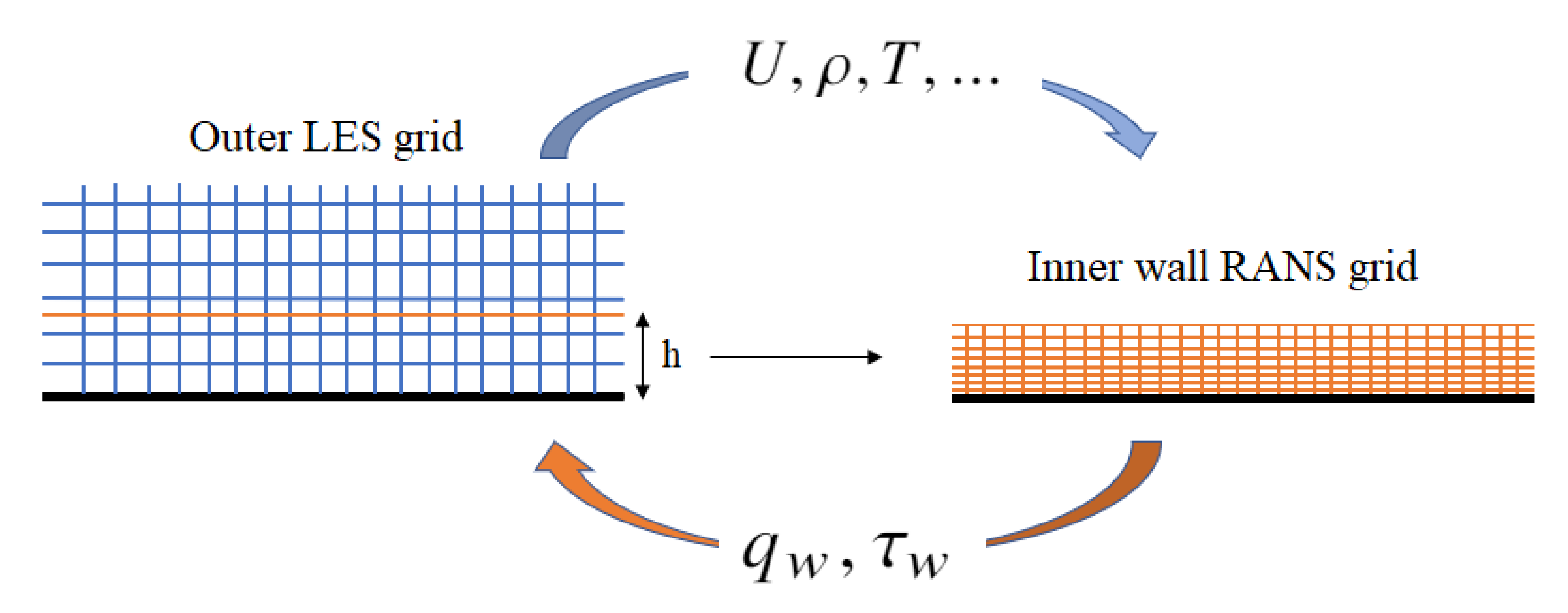
A WMLES that solves the fully-coupled RANS equations requires an auxiliary wall-layer grid to be provided (Figure 1). The inner layer RANS is solved in a grid that is refined in the wall-normal direction (in RANS context) and is embedded in the outer layer (wall-modeled) coarse LES mesh. At each time step, the wall-shear stress and wall-heat flux calculated from the wall-model solution are used as Neumann boundary conditions for the LES. The solutions from the LES are transferred to the inner-layer RANS model at the corresponding point. The matching point in the LES mesh where the RANS top boundary meets the LES mesh is not necessarily at the first off-wall LES nodes where subgrid modeling and numerical errors are large because of the poor near-wall grid resolution in the LES mesh [3].
2.3. Errors in Wall Modeling
Next, we discuss the numerical and subgrid-modeling errors in the first few grids off the wall. Since the wall model takes as input the solution from the LES at the first grid point, it means that the wall model is fed by inaccurate information. Therefore even a perfect wall model would not be able to accurately predict skin friction. The second error is the well-known LLM. The inner log-layer, provided by the RANS model and the outer log layer computed by LES are mismatched. It is reported that the total shear stress and heat flux between the LES and RANS has discrepancies at the matching location.
2.4. Flow Solver
An in-house finite-volume code is used to carry out WMLES. The code can capture discontinuities such as shockwaves while preserving the energy in turbulent regions [21]. Therefore, it is appropriate for the LES type of turbulent flow simulations. A skew-symmetric form of a collocated second order scheme with low numerical dispersion and dissipation is implemented to model the turbulent region in the combination of a semi-discrete, central difference scheme to capture discontinuities, with a switch based on the Ducros sensor [22]. This sensor allows the hybrid scheme to capture the discontinuity and predict the accurate decay of turbulent kinetic energy in turbulent regions, making the model suitable for the LES of compressible turbulent flows. The governing equations are integrated in time using the original implicit Euler scheme. The code was validated for numerous cases of compressible and incompressible flows [23,24,25,26]. The IDDES model is implemented in the solver to study the boundary layer separation and reattachment in transonic airfoils [27]. In addition, the IDDES-based WMLES approach is used to assess the WMLES performance in hypersonic flows with heat transfer [28].
2.5. Flow Configuration
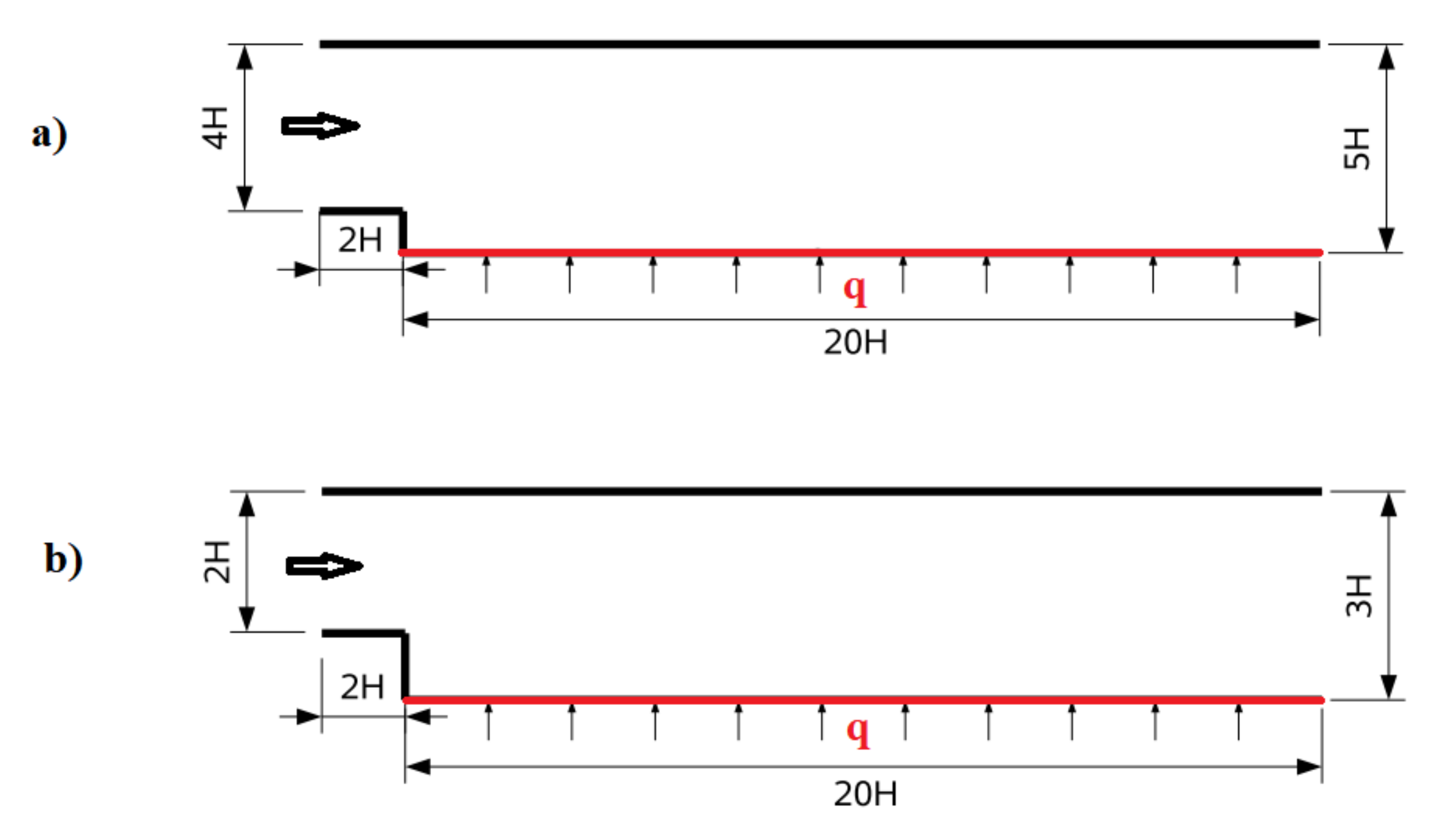
Two different flow configurations over backward-facing steps are considered. Figure 2a shows the first configuration in which the turbulent boundary layer at the edge of the step separates (fixed separation point) and reattaches at the bottom wall forming the recirculation region behind the step. The flow Reynolds number based on the step height ( m) is 28,000. The upstream flow conditions correspond to a developing channel flow of height 4H. The boundary layer developing at the lower wall separates at the step edge transforming into the free shear layer within the expanded channel section of height . The boundary layer thickness at the step edge is approximately equal to . This configuration is similar to the experimental database is provided by Vogel and Eaton et al. [29]. The lower wall in the channel after the expansion is heated by the heat flux W/m. In the spanwise direction and the wall normal direction . The streamwise spacing is set to reach . This domain was meshed with grid cells, resulting in about 3 million cells in total. For sufficient confidence in the computational results, the number of the girds is determined by a mesh convergence study.
Figure 2b shows the second configuration. The flow Reynolds number based on the step height ( m) is 5540. The upstream conditions correspond to fully-developed flow in a channel of height (inflow was generated by performing precursor channel flow calculations). An isothermal wall and two strong wall heat fluxes ( kW/m, 3 kW/m) are considered for the second configuration. All other walls are treated as adiabatic. Digital filter-based inlet boundary condition is used to generate synthetic turbulence-alike time series [30]. A non-reflecting boundary condition is imposed to attempts to reconstruct this kind of non-reflective scheme allows the sound wave flow smoothly out of the domain through the outlet. Two LES simulations serving as a computational reference in the present work have been performed by Akselvoll and Moin [31] and Keating et al. [32]. In the spanwise direction and in the wall normal direction . The streamwise spacing is set to reach .
3. Results and Discussion
Some selected results obtained by the IDDES model for both configurations are shown and discussed in this section. The reference experimental database (Kasagi and Matsunaga [33]; Vogel and Eaton [29]) are used for comparisons.
3.1. First Configuration
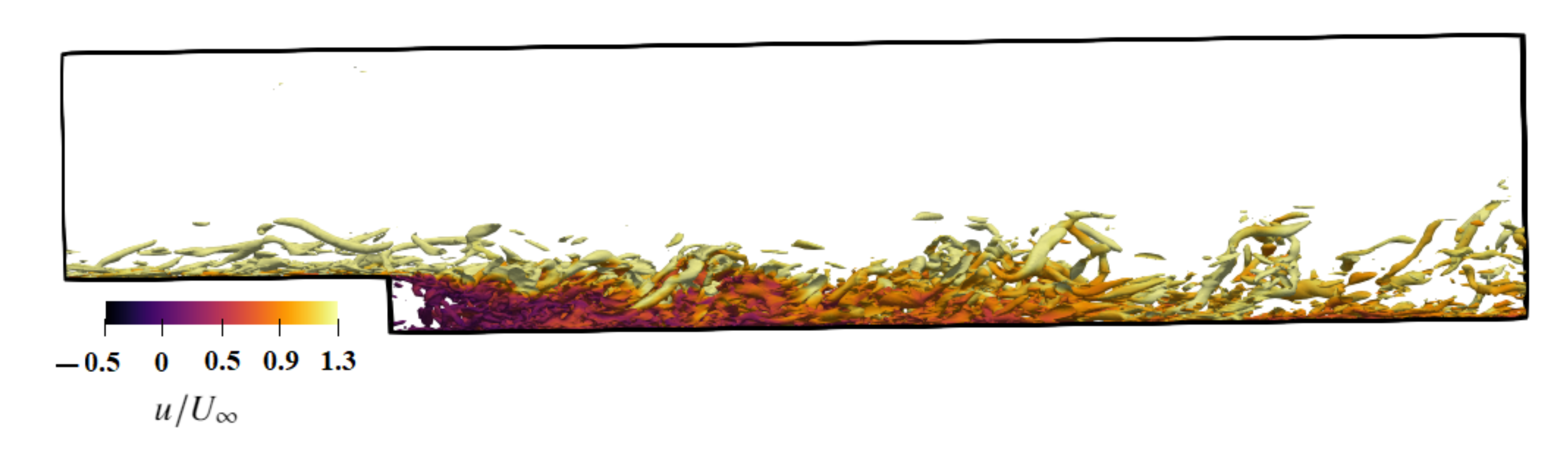
The results of the reattachment length obtained by several computational methods and experiment are summarized in Table 1. The IDDES model slightly overpredicts the mean reattachment point compared to the experimental and LES results. The iso-surface of Q colored with the instantaneous x-velocity is shown in Figure 3. The turbulence coherent Q-criterion, was originally introduced by Jeong and Hussain [34] to visualize a vortex, and it is defined as where and S are rotation and strain rate tensors, respectively. The coherent structures in the undisturbed boundary layer present classic streamwise elongated hairpin vortices. The Kelvin–Helmholtz instability at the edge of the step breaks the upcoming longitudinal structures. Near the reattachment line, some large-scale coherent structures in the boundary layer can be identified. In the recovery region, detached structures from the mixing layer are observed.
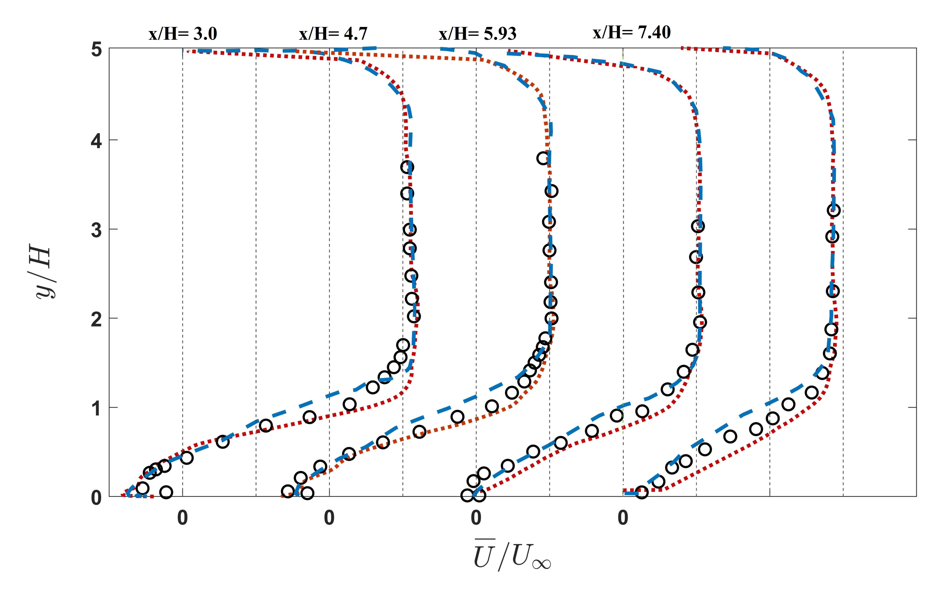
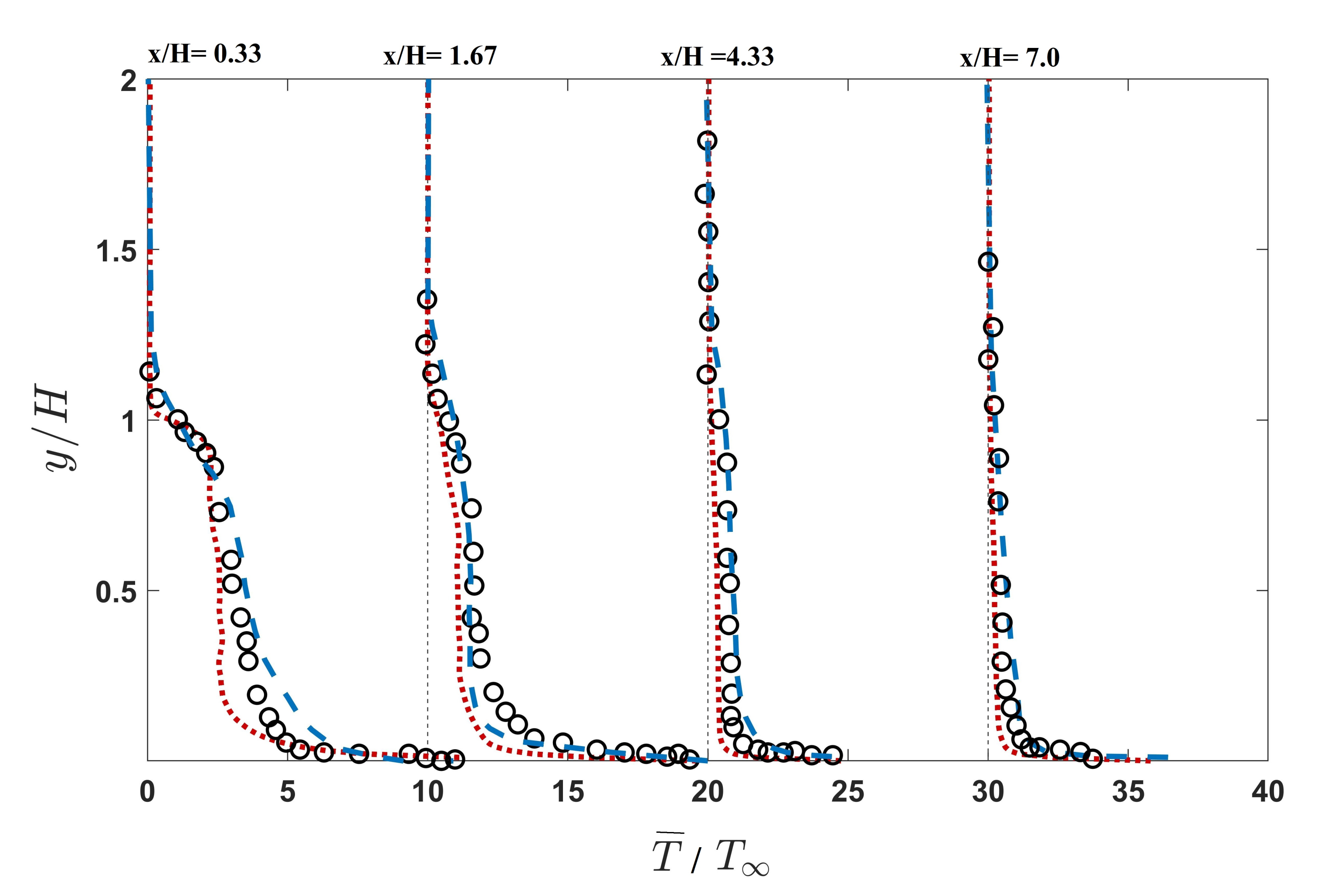
Figure 4 shows the evolution of the mean axial velocity profiles at selected streamwise locations. After the step, in the recirculation zone, the inner velocity is reduced with the thickening of the low-speed inner layer. At , 4.7, and 5.93, the negative value of velocity can be observed, indicating the appearance of the reverse flow. After the reattachment, the boundary layer redevelops and finally recovers close to an equilibrium state near the exit of the computational domain. It can be seen that IDDES profiles go under faster development compared to LES results however, they exhibit good agreement with the experimental results. Figure 5 depicts the development of the profiles of the mean temperature at several streamwise locations. Some deviations of the computed temperature field from the reference experiment are noticeable only immediately behind the step in the separation zone (locations and 1.67).
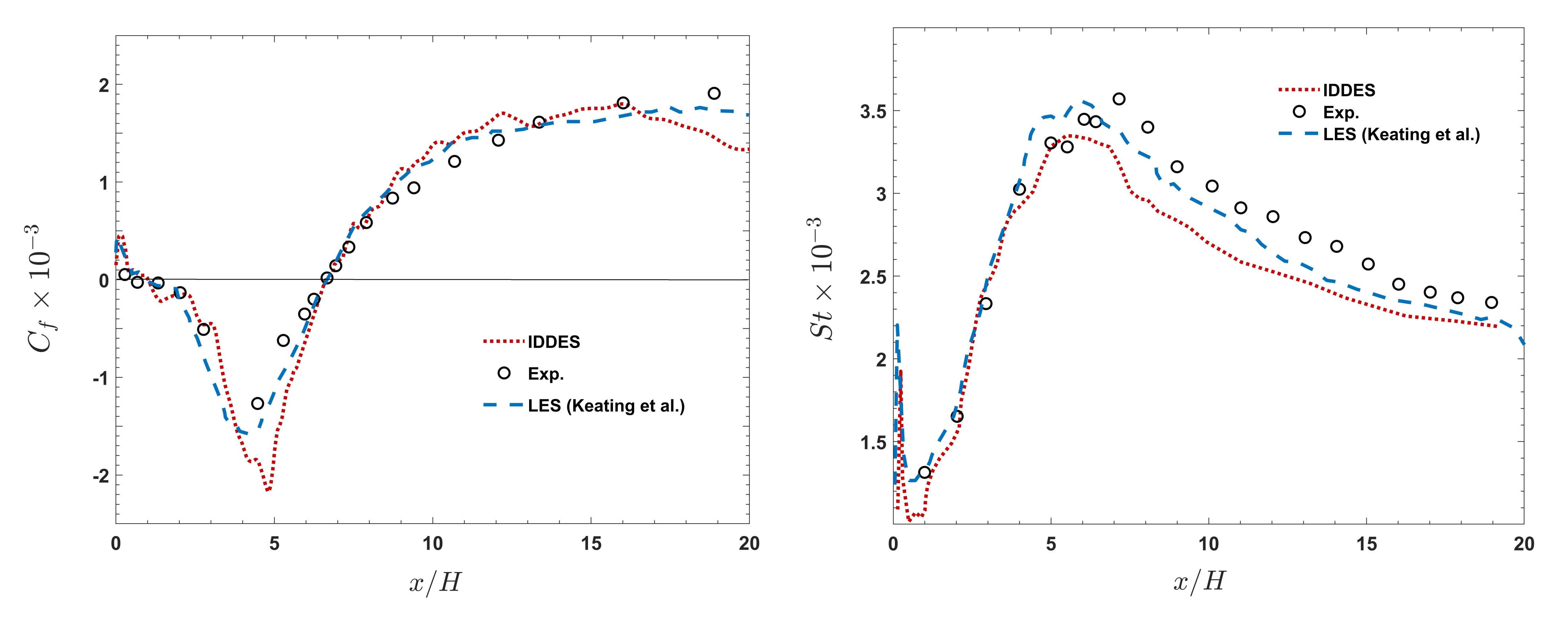
The evolution of the spatial distribution of the friction coefficient, and Stanton number, are shown Figure 6. The skin friction exhibits a clear plateau region with negative values, which indicates the existence of the separation bubble with reverse flows. The skin friction decreases with increasing the adverse pressure gradient and reaches the minimum value. After reaching the minimum value, begins to increase, and the reattachment point can also be identified by . Further downstream, the increase of slows down, which indicates the recovery of the turbulent boundary layer towards another equilibrium state. The IDDES predicted follows the LES and experimental results closely. However, the underprediction of is apparent for the wall with heat flux, especially in the separation region. The underprediction is more noticeable compared to LES-predicated . This underprediction which is reported in many cases of using the IDDES model is due to the the log-layer mismatch at the switching location. The St values show good agreements with LES and experimental results with an underprediction both in the recirculating and recovery regions. The reason can be attributed to the mean temperature profiles are shown in Figure 5. Since IDDES goes under a faster temperature recovery, the value of the IDDES-predicted St number is lower in this region.
3.2. Second Configuration
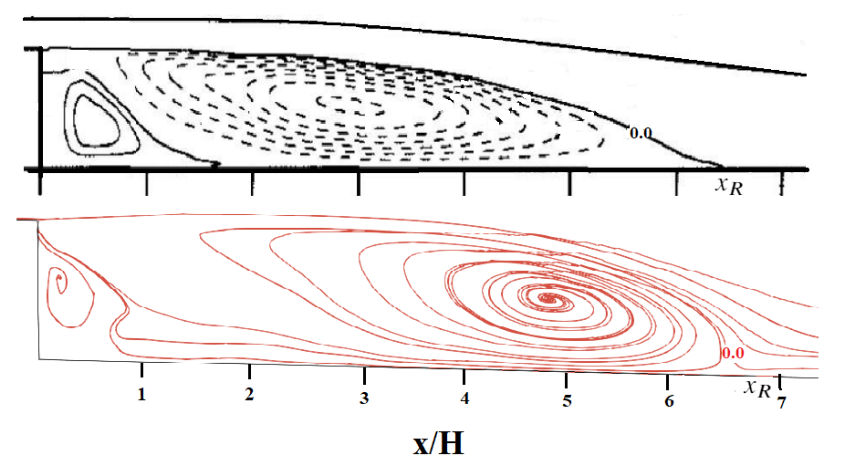
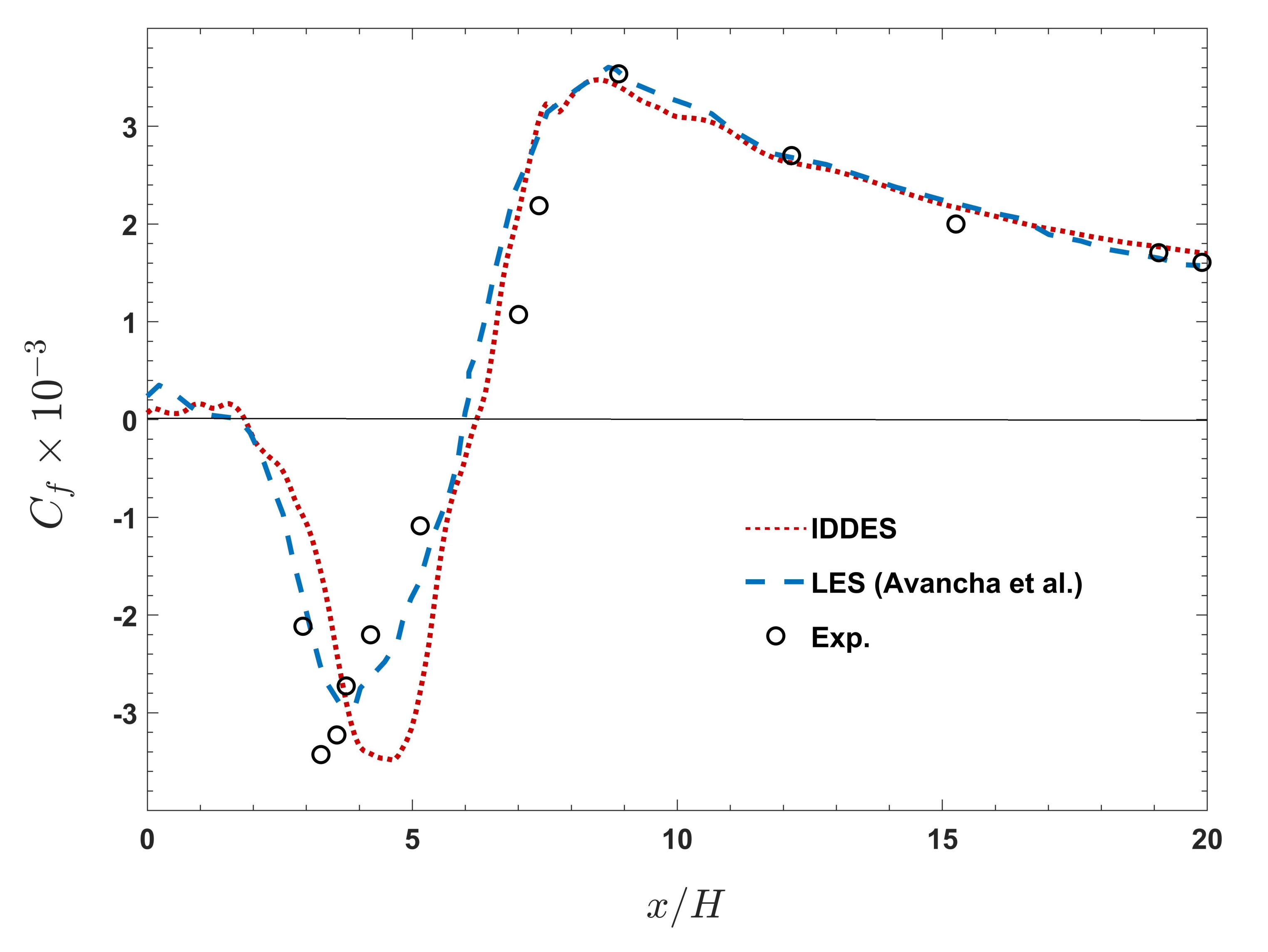
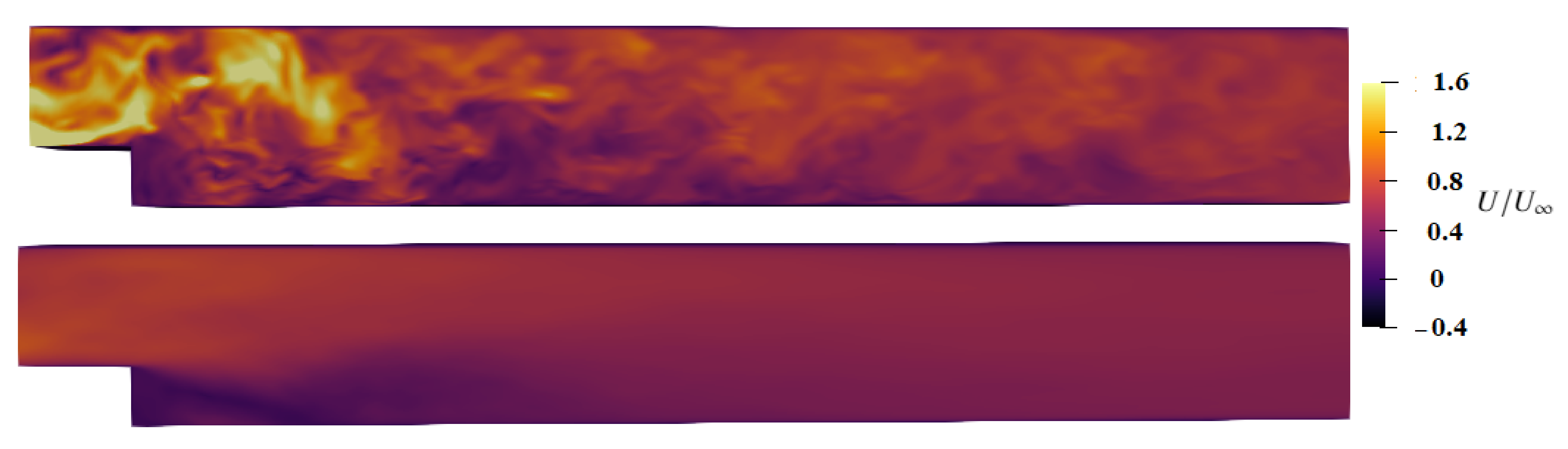
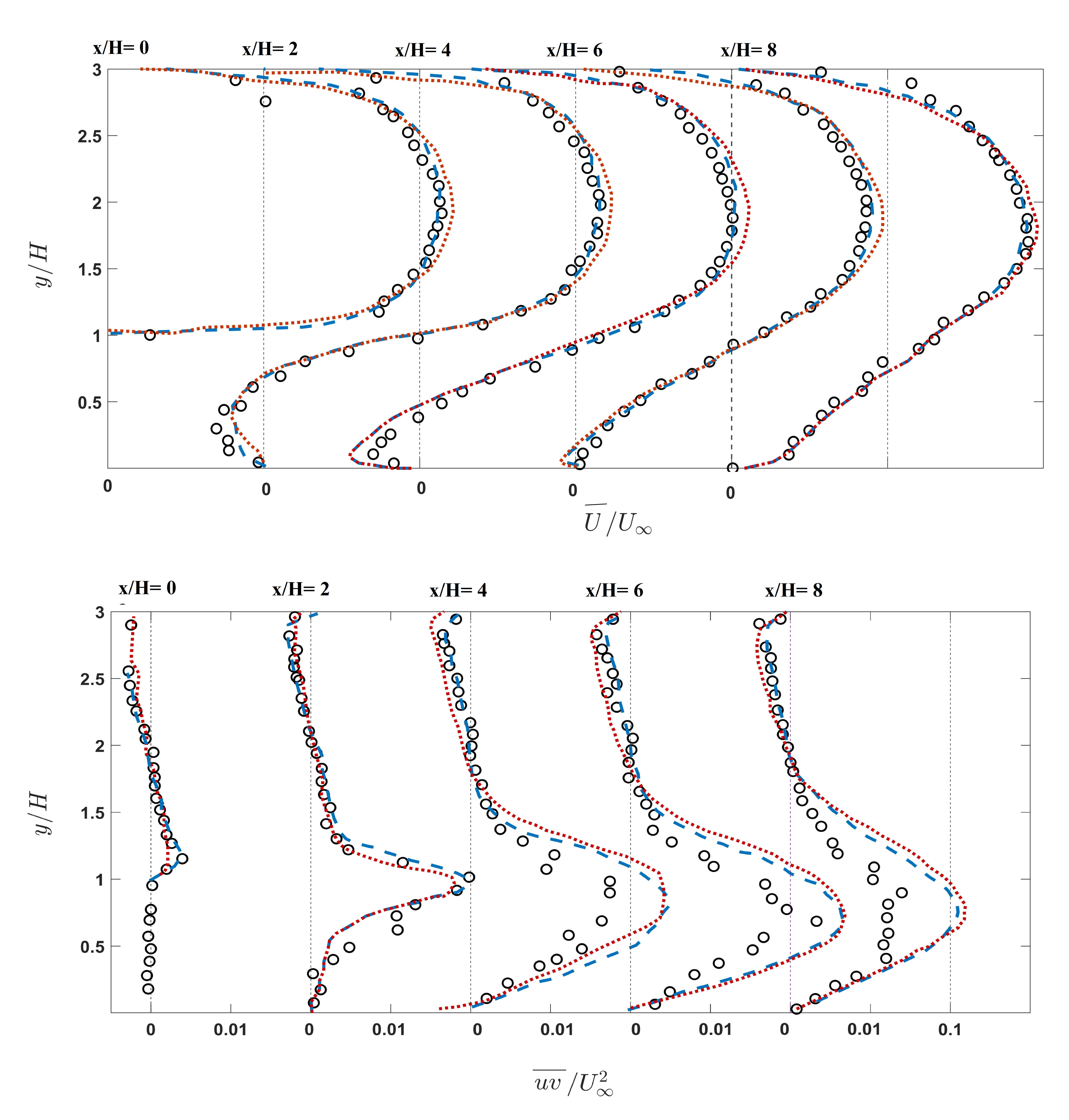
The second configuration represents the isothermal wall and also the strong heat flux of the wall, which can affect the fluid properties. The comparison of the mean streamline patterns in the recirculation region for the isothermal case, Figure 7, shows that the IDDES model yields the reattachment length of , which is slightly larger compared to the experimental one . A discrepancy also is apparent in the corner bubble. The core of the recilculation region moved forward for the IDDES model compared to the analogous experiment, and it resides near the reattachment point. The discrepancy is seen between the IDDES and the experiment in the scale and location of the vortex structures for the recirculation zone can be attributed to the predicted properties of the boundary layer in the vicinity of the reattachment location. The evolution obtained by the IDDES model agrees reasonably with experimental results with respect to the reattachment length as shown in Figure 8. In contrast, the LES result reports the reattachment length to be slightly shorter. Furthermore, the negative peak value does not suffer from the significant underprediction for the isothermal wall case. The instantaneous and mean velocity for the isothermal wall are shown in Figure 9. Figure 10 shows the mean velocity and Reynolds shear stress in various streamwise locations. It can be seen that the results from the IDDES model and experimental data have very good agreement in all distinct regions of the backward-facing step with an isothermal wall.
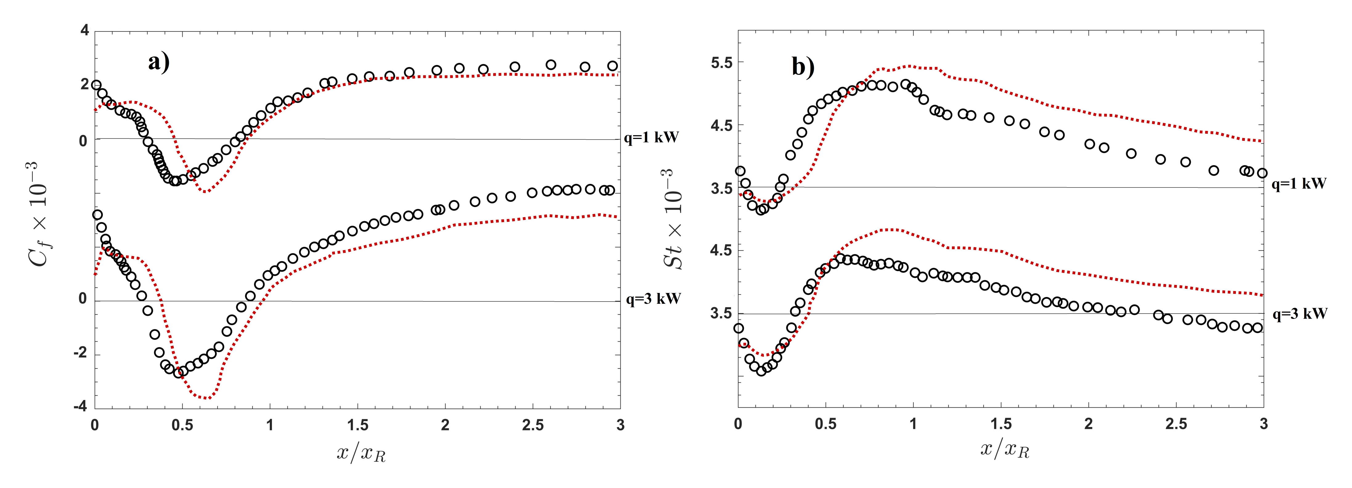
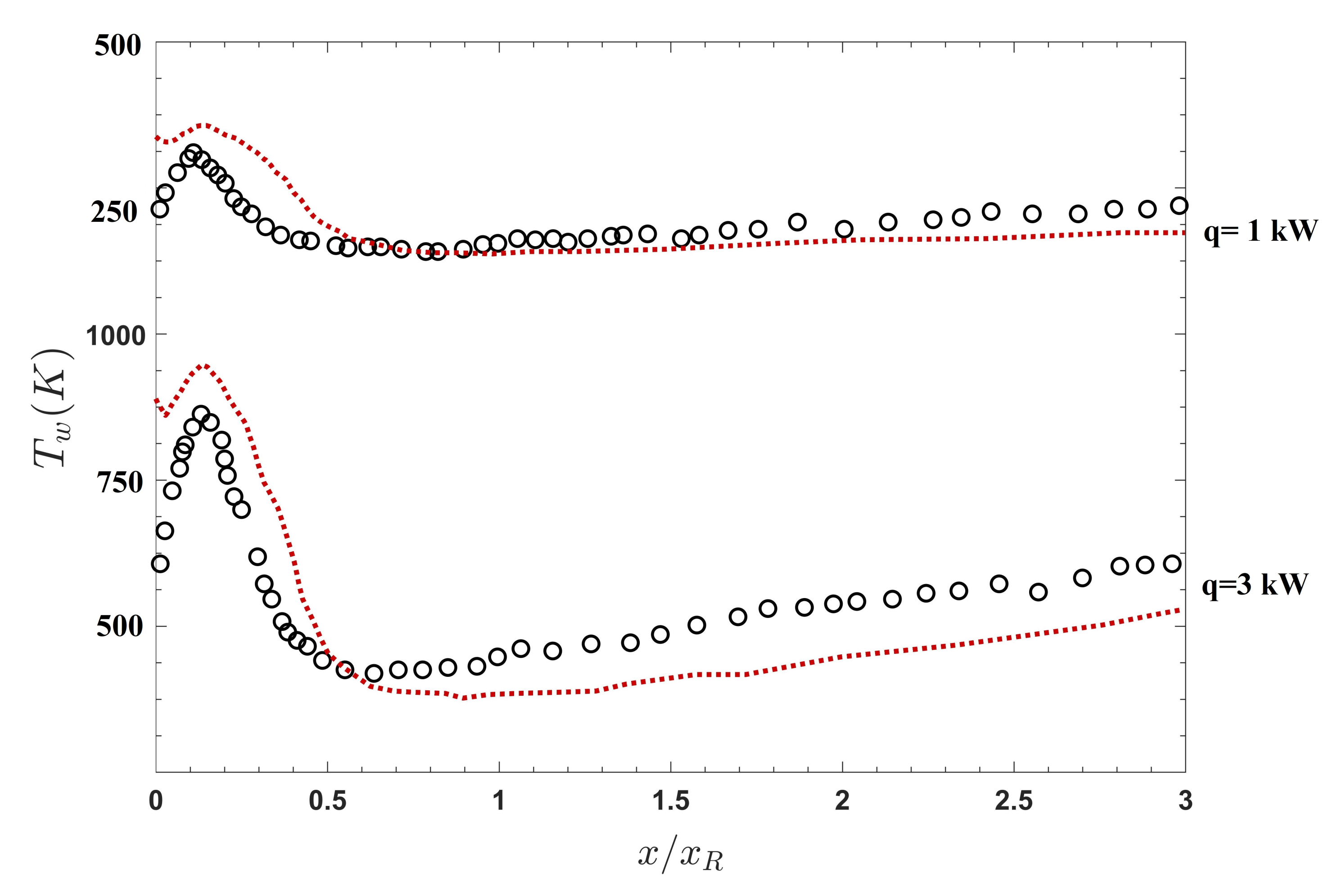
It was discussed that the IDDES model suffers from the underprediction of the skin friction for the case of the wall with a mild heat transfer rate (first configuration). The simulations of the cases with an intense wall heat transfer are performed for two different wall heat fluxes, and 3 kW/m. The evolution in the streamwise direction displayed in Figure 11a reveals a very interesting dependence on the heat flux level supplied. Directly comparing the mean and St (Figure 11b) with the experimental data reveals that as the heat flux increases, the IDDES model declines to predict the accurate . The St prediction also follows the same trend. However, it is apparent that the strong temperature variation does not significantly influence the reattachment length. Figure 12 shows that the trend of the wall temperature variations agree very well with the experimental reference data. The position of the peaks of the temperature is well predicted by the IDDES model. It can be seen that the temperature is overpredicted by the computational results in the separation zone for both cases; however, it suffers from an underprediction in the recovery region. The overall prediction is quite acceptable for the case of the wall with the lower heat transfer rate ( kW/m).
4. Conclusions
This study is conducted to assess the performance of the IDDES model acting as a WMLES in separated flows with heat transfer. Two configurations of backward-facing steps with an isothermal wall and walls with heat transfer are considered, and the results are compared to previously-published LES and experimental data. Qualitatively, the results obtained by the IDDES model with respect to the reattachment lengths, and Stanton number distributions, fluid flow, and thermal fields follow the reference experiment and reference LES results closely. For the case of the wall with heat flux, the skin friction and Stanton number are underpredicted by the IDDES model however, the underprediction is less significant for the isothermal wall case. The simulations of the cases with intense wall heat transfers reveal an interesting dependence on the heat flux level supplied, as the heat flux increases, the IDDES model declines to predict the accurate . A possibility for future work is to examine the IDDES model for a broader range of Reynolds numbers, including high speed flows, to assess the performance of the IDDES model in high Reynolds number flows with various heat transfer configurations. A possibility for future work is improving the error of the wall modeling by investigating the blending function between RANS and LES to find the optimal switching location for the IDDES model.
Funding
This research received no external funding.
Acknowledgments
This work used the Extreme Science and Engineering Discovery Environment (XSEDE), which is supported by National Science Foundation, grant number ACI-1548562.
Conflicts of Interest
The author declares no conflict of interest.
References
- Yang, X.; Zafar, S.; Wang, J.X.; Xiao, H. Predictive large-eddy-simulation wall modeling via physics-informed neural networks. Phys. Rev. Fluids 2019, 4. [Google Scholar] [CrossRef]
- Larsson, J.; Kawai, S.; Bodart, J.; Bermejo-Moreno, I. Large eddy simulation with modeled wall-stress: Recent progress and future directions. Mech. Eng. Rev. 2016, 3, 15-00418. [Google Scholar] [CrossRef] [Green Version]
- Soshi, K.; Johan, L. Wall modeling in large-eddy simulation: Predicting accurate skin friction at very high Reynolds number. In Proceedings of the 49th AIAA Aerospace Sciences Meeting including the New Horizons Forum and Aerospace Exposition, Orlando, FL, USA, 4–7 January 2011. [Google Scholar] [CrossRef]
- Lozano-Durán, A.; Bae, H.J. Self-critical machine-learning wall-modeled LES for external aerodynamics. arXiv 2020, arXiv:2012.10005. [Google Scholar]
- Park, G.I.; Moin, P. Space-time characteristics of wall-pressure and wall shear-stress fluctuations in wall-modeled large eddy simulation. Phys. Rev. Fluids 2016, 1, 024404. [Google Scholar] [CrossRef] [PubMed]
- Nikitin, N.V.; Nicoud, F.; Wasistho, B.; Squires, K.D.; Spalart, P.R. An approach to wall modeling in large-eddy simulations. Phys. Fluids 2000, 12, 1629–1632. [Google Scholar] [CrossRef]
- Piomelli, U.; Balaras, E.; Pasinato, H.; Squires, K.D.; Spalart, P.R. The inner–outer layer interface in large-eddy simulations with wall-layer models. Int. J. Heat Fluid Flow 2003, 24, 538–550. [Google Scholar] [CrossRef] [Green Version]
- Shur, M.L.; Spalart, P.R.; Strelets, M.K.; Travin, A.K. A hybrid RANS-LES approach with delayed-DES and wall-modelled LES capabilities. Int. J. Heat Fluid Flow 2008, 29, 1638–1649. [Google Scholar] [CrossRef]
- Shur, M.; Spalart, P.; Strelets, M.; Travin, A. Synthetic Turbulence Generators for RANS-LES Interfaces in Zonal Simulations of Aerodynamic and Aeroacoustic Problems. Flow Turbul. Combust. 2014, 93, 63–92. [Google Scholar] [CrossRef]
- Mockett, C.; Fuchs, M.; Thiele, F. Progress in DES for wall-modelled LES of complex internal flows. Comput. Fluids 2012, 65, 44–55. [Google Scholar] [CrossRef]
- Gieseking, D.A.; Choi, J.I.; Edwards, J.R.; Hassan, H.A. Compressible-Flow Simulations Using a New Large-Eddy Simulation/Reynolds-Averaged Navier-Stokes Model. AIAA J. 2011, 49, 2194–2209. [Google Scholar] [CrossRef]
- Peterson, D.M.; Candler, G.V. Simulations of Mixing for Normal and Low-Angled Injection into a Supersonic Crossflow. AIAA J. 2011, 49, 2792–2804. [Google Scholar] [CrossRef]
- Saini, R.; Karimi, N.; Duan, L.; Sadiki, A.; Mehdizadeh, A. Effects of Near Wall Modeling in the Improved-Delayed-Detached-Eddy-Simulation (IDDES) Methodology. Entropy 2018, 20, 771. [Google Scholar] [CrossRef] [Green Version]
- Guseva, E.; Garbaruk, A.; Strelets, M. Assessment of Delayed DES and Improved Delayed DES Combined with a Shear-Layer-Adapted Subgrid Length-Scale in Separated Flows. Flow Turbul. Combust. 2017, 98. [Google Scholar] [CrossRef]
- Xu, H.H.A.; Yang, X.I.A.; Milani, P.M. Assessing Wall-Modeled Large-Eddy Simulation for Low-Speed Flows with Heat Transfer. AIAA J. 2021, 59, 2060–2069. [Google Scholar] [CrossRef]
- Jakirlić, S.; Kniesner, B. Near-Wall RANS Modelling in LES of Heat Transfer in Backward-Facing Step Flows Under Conditions of Constant and Variable Fluid Properties. In American Society of Mechanical Engineers, Fluids Engineering Division; FEDSM: Montreal, QC, Canada, 2010; Volume 1, pp. 2489–2502. [Google Scholar] [CrossRef]
- Spalart, P.R.; Jou, W.-H.; Strelets, M.; Allmaras, S.R. Comments on the Feasibility of LES for Wings, and on a Hybrid RANS/LES Approach. In Proceedings of the First AFOSR International Conference on DNS/LES, Ruston, LA, USA, 4–8 August 1997. [Google Scholar]
- Spalart, P.R.; Deck, S.; Shur, M.L.; Squires, K.D.; Strelets, M.K.; Travin, A. A New Version of Detached-eddy Simulation, Resistant to Ambiguous Grid Densities. Theor. Comput. Fluid Dyn. 2006, 20, 181–195. [Google Scholar] [CrossRef]
- Hirsch, C. Numerical Computation of Internal and External Flows, 2nd ed.; Elsevier: Amsterdam, The Nederlands, 2007. [Google Scholar] [CrossRef]
- Gritskevich, M.S.; Garbaruk, A.V.; Menter, F.R. Development of DDES and IDDES formulations to the k-ω shear stress transport model. Flow Turbul. Combust. 2011, 5, 23–42. [Google Scholar] [CrossRef]
- Zangeneh, R. A New Framework for Modeling Shock-Turbulence Interactions. SAE Int. J. Aerospace 2020. [Google Scholar] [CrossRef]
- Ducros, F.; Ferrand, V.; Nicoud, F.; Weber, C.; Darracq, D.; Gacherieu, C.; Poinsot, T. Large-Eddy Simulation of the Shock/Turbulence Interaction. J. Comput. Phys. 1999, 152, 517–549. [Google Scholar] [CrossRef]
- Zangeneh, R. Development of a New Algorithm for Modeling Viscous Transonic Flow on Unstructured Grids at High Reynolds-Numbers. J. Fluids Eng. 2020. [Google Scholar] [CrossRef]
- Zangeneh, R. Evaluation of reattaching Shear-layer in Compressible Turbulent Flows; A Large-Eddy Simulation Approach. In Fluid Engineering Division; ASME: New York, NY, USA, 2020. [Google Scholar] [CrossRef]
- Zangeneh, R. Numerical Analysis of Transonic Flow around Cones. Open J. Fluid Dyn. 2020, 10, 279–290. [Google Scholar] [CrossRef]
- Zangeneh, R. Development of a deep-learning model to improve large eddy simulations of turbulent flows. In Proceedings of the 5th Thermal and Fluids Engineering Conference (TFEC), New Orleans, LA, USA, 5–8 April 2020. [Google Scholar] [CrossRef]
- Zangeneh, R. Parametric Study of Separation and Reattachment in Transonic Airfoil Flows. AIAA J. 2021, 18, 1–10. [Google Scholar] [CrossRef]
- Zangeneh, R. Wall-modeled Large-eddy Simulation of Hypersonic Turbulent Boundary-layers. In AIAA Scitech 2021 Forum; American Institute of Aeronautics and Astronautics: New Reston, VA, USA, 2021. [Google Scholar]
- Vogel, J.; Eaton, J. Combined Heat Transfer and Fluid Dynamic Measurements Downstream of a Backward-Facing Step. J. Heat Transf. Trans. ASME 1985, 107, 922–929. [Google Scholar] [CrossRef]
- Klein, M.; Sadiki, A. A digital filter based generation of inflow data for spatially developing direct numerical or large eddy simulations. J. Comput. Phys. 2003, 166, 652–665. [Google Scholar] [CrossRef]
- Akselvoll, K.; Moin, P. Large-eddy simulation of turbulent confined coannular jets. J. Fluid Mech. 1996, 315, 387–411. [Google Scholar] [CrossRef]
- Keating, A.; Piomelli, U.; Bremhorst, K.; Nešić, S. Large-eddy simulation of heat transfer downstream of a backward-facing step. J. Turbul. 2004, 5, 20. [Google Scholar] [CrossRef] [Green Version]
- Kasagi, N.; Matsunaga, A. Three-dimensional particle-tracking velocimetry measurement of turbulence statistics and energy budget in a backward-facing step flow. Int. J. Heat Fluid Flow 1995, 16, 477–485. [Google Scholar] [CrossRef]
- Jeong, J.; Hussain, F. On the identification of a vortex. J. Fluid Mech. 2000, 285, 69–94. [Google Scholar] [CrossRef]
Figure 1.
Schematic of the mesh setup for wall-modeled large-eddy simulations.

Figure 2.
Computational domain for (a) first configuration and (b) second configuration.

Figure 3.
Iso-surface of Q-criterion colored by the instantaneous streamwise velocity.

Figure 4.
Mean axial velocity profiles in various streamwise locations. IDDES (red dotted line), LES (blue dashed line), and corresponding experiment (circles).
Figure 4.
Mean axial velocity profiles in various streamwise locations. IDDES (red dotted line), LES (blue dashed line), and corresponding experiment (circles).

Figure 5.
Mean temperature profiles in various streamwise locations. IDDES (red dotted line), LES (blue dashed line), and corresponding experiment (circles).
Figure 5.
Mean temperature profiles in various streamwise locations. IDDES (red dotted line), LES (blue dashed line), and corresponding experiment (circles).

Figure 6.
The distribution of the mean skin friction and Stanton number.

Figure 7.
Mean streamlines obtained experimentally, recreated from [29] (upper) and applying the IDDES model (lower) for the isothermal wall. (Upper figure reproduced with permission from [16], published by American Society of Mechanical Engineers 2010).

Figure 8.
The distribution of the mean skin friction for the isothermal wall case.

Figure 9.
The instantaneous (upper) and mean velocity (lower) in the isothermal wall configuration.

Figure 10.
The mean velocity and Reynolds shear stress in various streamwise location for the isothermal wall case. IDDES (red dotted line), LES (blue dashed line), and corresponding experiment (circles).
Figure 10.
The mean velocity and Reynolds shear stress in various streamwise location for the isothermal wall case. IDDES (red dotted line), LES (blue dashed line), and corresponding experiment (circles).

Figure 11.
The distribution of (a) the mean skin friction and (b) Stanton number for the cases with intense wall heat transfer. IDDES (red dotted line), corresponding experiment (circles).
Figure 11.
The distribution of (a) the mean skin friction and (b) Stanton number for the cases with intense wall heat transfer. IDDES (red dotted line), corresponding experiment (circles).

Figure 12.
The mean temperature variation for the cases with intense wall heat transfer. IDDES (red dotted line), corresponding experiment (circles).
Figure 12.
The mean temperature variation for the cases with intense wall heat transfer. IDDES (red dotted line), corresponding experiment (circles).


Table 1.
Comparison of reattachment lengths obtained by the IDDES model and available experimental and LES data.
Publisher’s Note: MDPI stays neutral with regard to jurisdictional claims in published maps and institutional affiliations. |
© 2021 by the author. Licensee MDPI, Basel, Switzerland. This article is an open access article distributed under the terms and conditions of the Creative Commons Attribution (CC BY) license (https://creativecommons.org/licenses/by/4.0/).
Share and Cite
MDPI and ACS Style
Zangeneh, R. Assessing IDDES-Based Wall-Modeled Large-Eddy Simulation (WMLES) for Separated Flows with Heat Transfer. Fluids 2021, 6, 246. https://0-doi-org.brum.beds.ac.uk/10.3390/fluids6070246
AMA Style
Zangeneh R. Assessing IDDES-Based Wall-Modeled Large-Eddy Simulation (WMLES) for Separated Flows with Heat Transfer. Fluids. 2021; 6(7):246. https://0-doi-org.brum.beds.ac.uk/10.3390/fluids6070246
Chicago/Turabian StyleZangeneh, Rozie. 2021. "Assessing IDDES-Based Wall-Modeled Large-Eddy Simulation (WMLES) for Separated Flows with Heat Transfer" Fluids 6, no. 7: 246. https://0-doi-org.brum.beds.ac.uk/10.3390/fluids6070246