1. Introduction
Currently under development are various liquid metal cooled nuclear reactor projects related to Generation IV reactors. Improving the calculation accuracy when justifying the thermohydraulic characteristics of a fast reactor is an important applied problem, since this can affect its reliability and operational safety. On the other hand, the refinement of the calculation makes it possible to reduce the degree of conservatism in the design. One of the design features of a typical fast reactor with fuel assemblies of cassette type in the core is the presence of an inter-wrapper space (IWS) in the core. This actually means the presence of, simultaneously, two coolant flows in the reactor core: one of them is the main one, passing inside the fuel assembly and responsible for heat removal from the fuel rods, and the other, passing through the IWS and usually making up a few percent of the total flow through the reactor. Both streams, in the course of their movement, exchange heat through the fuel assembly. The degree of influence of the processes in the IWS on the parameters of the reactor and the core as a whole depends on the design features of the reactor and the investigated mode of its operation. This influence was considered in [
1].
The fraction of heat removed from the core through the IWS in the rated power mode of the reactor is usually small, but even in this case, the spatial non-uniformity of the velocity field in the IWS can noticeably affect the temperatures in some fuel sub-assembles of the core. The influence of processes in the inter-wrapper space on heat transfer in the core increases with primary flow rate decrease in the reactor. The need to take into account the influence of IWS arises when studying transient modes and some beyond design basis accidents. For example, the key point in the study of a beyond design basis accident caused by the loss of flow in the primary and secondary circuits of the reactor with a simultaneous failure of the emergency protection system is the possibility of more accurate modeling of the effects of reactivity, and, in particular, the effect associated with the shape change of the core during heating. In this case, the picture of the bends of the fuel assemblies largely depends on the azimuthal temperature gradients over the cross section of the fuel assembly wrapper, which, in turn, depend on variation of the spatial temperature distribution of sodium that washes the outer surface of the wrapper. Adequate modeling of the thermo-hydrodynamic processes in the IWS is also important when investigating the ULOF accident. The sodium boiling in the IWS can make a significant contribution to the reactivity, and seriously affect the course of the accident and its consequences.
The influence of processes in the inter-wrapper space on heat transfer in the core is most clearly manifested in the emergency heat removal mode, when there is no forced circulation along the circuits, and a significant fraction of the heat of the decay heat released in the fuel elements is removed due to the circulation of sodium in the IWS. This effect becomes especially significant in the design version of a fast reactor equipped with decay heat exchangers immersed in the upper reactor plenum. In this case, the “cold” coolant from the outlet windows of the decay heat exchanger is discharged first into the upper plenum of the reactor, and then into the peripheral part of the inter-wrapper space, where it first moves in a radial direction to the center of the core, where it then heats up and forms an ascending flow. As a result, the efficiency of heat removal from the core and the prevention of emergency overheating of fuel elements is largely determined by the resistance to the flow during its horizontal movement towards the center in the IWS.
Justification of nuclear reactors is currently carried out mainly using computational codes of varying degrees of detail. Full CFD modeling of a nuclear reactor, taking into account all the features of its flow path, requires unrealistically large expenditures of computer resources, therefore, in practice, the porous medium approximation is often used to describe heat transfer in separate parts of the reactor. At the same time, detailed modeling of the flow and heat exchange in such small structures as the inter-pin or inter-wrapper space is abandoned, and the interaction with the “framework” of the porous medium is described integrally by introducing mass friction forces into the momentum equations. These friction forces in pin-bundle structures depend on the flow direction; therefore, the corresponding friction coefficients have anisotropy. Additionally, if the empirical correlations for determining the friction coefficients for rod bundles, both in the longitudinal and transverse directions are available, for example [
2], then there are no such correlations for calculating of friction coefficients for the transverse flow of liquid in rod bundles formed by hexagonal cylinders.
Currently, the idea of replacing full-scale experiments by calculations using precision codes is actively developing, The use of such codes makes it possible to check the possible flow modes in various equipment of the reactor plant in a wide range of parameters, without resorting to the need to construct experimental facility. The obtained results can be used to develop correlations describing various processes of heat and mass transfer in the core and circuit elements. The correlations can later be used in engineer codes that use the subchannel technique or the porous medium approximation.
It is proposed to implement this approach and to use the precision scalable eddy-resolving CFD code CONV-3D [
3,
4]. The code is developed at the Nuclear Safety Institute of the Russian Academy of Sciences (IBRAE) and based on the DNS approximation. CONV-3D code was validated against the wide set of thermal-hydraulic experiments [
5,
6]. The code is intended for performing precision thermo-hydrodynamic calculations in fuel assemblies, core, and other sections of fast reactor circuits. The computational core of the program is based on the finite volume method (FVM) and is used to solve the Navier–Stokes equation with both constant and variable coefficients. The program allows us to carry out calculations on Cartesian and IBM grids.
Thermo-hydrodynamic processes in the CONV-3D are modeled using nonstationary Navier–Stokes equations in natural variables together with the energy equation [
3,
4,
5]:
where
is the density;
u, v and
w are the components of the velocity vector;
p is the pressure;
are the symmetric components of the symmetric viscous-stress tensor;
are the components of the gravitational force vector;
t is the time;
v = (
u, v, w) is the velocity vector;
is the enthalpy;
is the thermal conductivity;
T is the temperature;
is the initial temperature;
c is the specific heat;
The numerical implementation of splitting schemes for the Navier-Stokes equations in the CONV-3D is performed in the operator-difference formulation as a two-step procedure with pressure adjustment. To obtain a time-integrated scheme for the energy equation, the operators of the equation are split into two parts associated with the enthalpy and temperature, which gives a two-step procedure. The operators in the equation of motion are also split into two parts: the transfer of velocity by convection/diffusion, a pressure gradient. More details about the numerical algorithm implemented in the CONV-3D are outlined in [
4].
3. Computational Mesh and Boundary Conditions
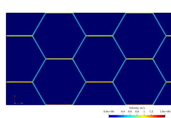
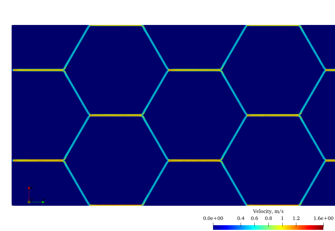
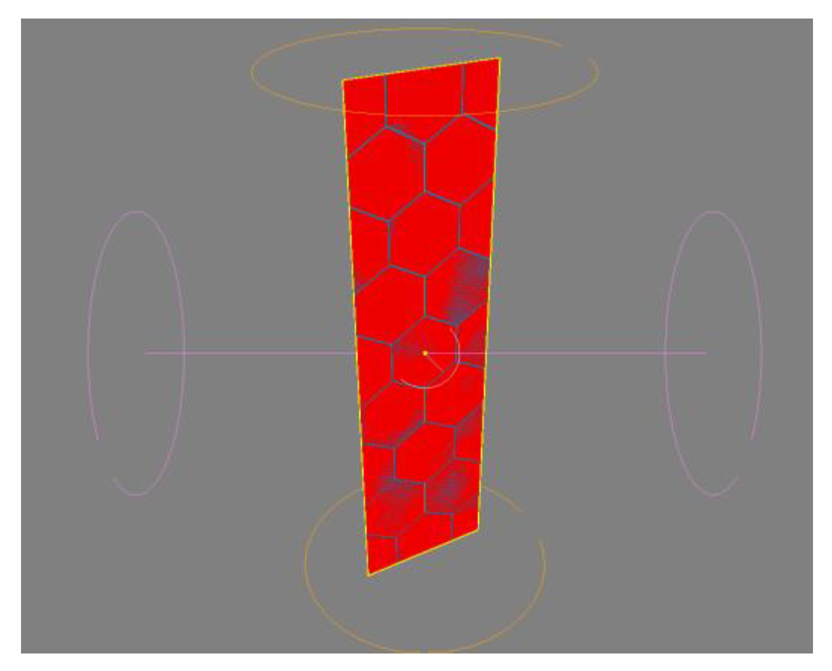
The geometry of the computational domain (
Figure 2) was constructed using the Geometry Editor embedded in the code. As boundary conditions, slip conditions were set on the lateral, lower and upper surfaces of a rectangular prism, and “pumps” with positive and negative flow rates were set at the inlet and outlet of the design area, which provided a constant flow simulation. The meshing of the computational domain consisted of 4099 cells in the longitudinal direction, 1025 cells in the transverse direction and 9 cells in the vertical direction. All calculations were carried out on a SENPAI computing cluster, (4 nodes, 160 cores, 1.5 TB RAM, 8 TB HDD, 10 TFLOPS, Intel
® Xeon
® Gold 6230 CPU 2.1 GHz) with parallelization into 32 physical cores. The time spent on one iteration was approximately 10 s.
The calculation began with an initial approach and continued until the stationary regime was reached. The solution was considered as steady after calculation, during a time interval that was equal to double transport time of passing the domain by coolant. Then, one more transport interval was calculated for the control of stability and calculations of time-averaged parameters of the flow.
4. Calculation Results
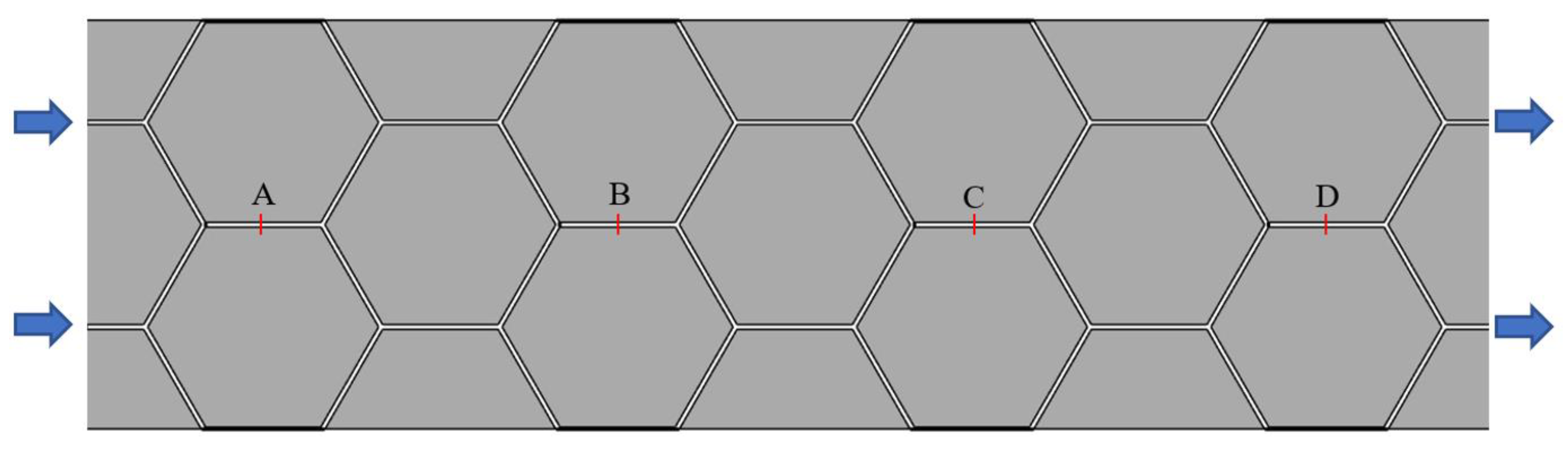
Eight calculations were performed with different values of the coolant velocity at the entrance to the computational domain. For each series of calculations, the pressure drop was determined between sections A and B, B and C, C and D, as shown on
Figure 1.
The calculated pressure drops for various values of the flow rate at the entrance are presented in the
Table 1.
The influence of the boundary conditions can be seen from the results, since the pressure drop in sections A–B and C–D differs from the difference between sections B and C. However, the deviation in the entire investigated range of Reynolds numbers is less than 3%.
The coefficient of anisotropy of friction in the bundles is usually defined as the ratio of pressure drops:
where ∆
pr and ∆
pz indicate the pressure drops per unit length in the transverse and longitudinal directions, respectively.
Calculated with CONV-3D, the pressure drops ∆p
r were compared with the pressure losses ∆
pz, calculated using the known empirical relationship [
2] to determine the hydraulic resistance of a flat channel:
where
ξ = 0.3164
/Re0.25 and hydraulic diameter
dH is equal to double width of inter cassette gap.
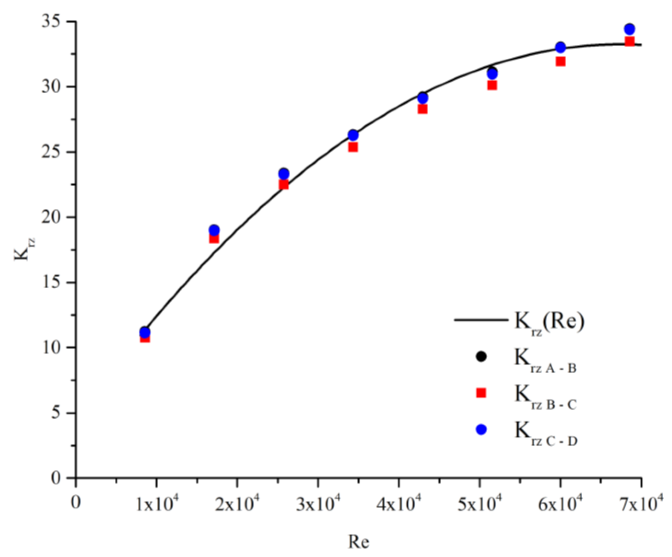
The results of calculating the coefficient of friction anisotropy from the Reynolds number are presented in
Table 2.
The results of calculating of the friction anisotropy coefficient versus Re number are approximated by a polynomial of the 2nd degree:
and are shown on
Figure 3. The maximum deviation of the approximating curve from the calculated values is less than 6%.


