

Modeling and Experimental Characterization of a Clutch Control Strategy Using a Magnetorheological Fluid

1
Department of Mechatronics, Silesian University of Technology, Akademicka 2A, 44-100 Gliwice, Poland
2
Department of Electrical, Electronics and Informatics Engineering, University of Catania, Viale Andrea Doria, 6, 95125 Catania, Italy
3
Department of Mathematics Applications and Methods for Artificial Intelligence, Faculty of Applied Mathematics, Silesian University of Technology, 44-100 Gliwice, Poland
*
Author to whom correspondence should be addressed.
Fluids 2023, 8(5), 145; https://0-doi-org.brum.beds.ac.uk/10.3390/fluids8050145
Submission received: 13 March 2023
/
Revised: 8 April 2023
/
Accepted: 26 April 2023
/
Published: 29 April 2023
(This article belongs to the Special Issue The Recent Advances in Magnetorheological Fluids)
Abstract
:In this paper, the characterization of a new clutch control strategy by means of a magnetorheological fluid (MR) has been investigated. The clutch system was designed and manufactured in the laboratory in order to determine its static and dynamic characteristics. As a result of experimental measurements, the torque control of the developed MR clutch was determined in the frequency and time domains, as were the analytical relationships describing the connection between the control and controlled variables. The obtained results demonstrate that the analytical models are in good agreement with the experimental data, with an overall error of about 7%.
1. Introduction
Nowadays, magnetorheological fluids (MR) are applied in many torque transmission devices mainly used in low power conditions, such as brakes, clutches and mechanical equipment such as hydraulic valves, dampers and robotic arms [1,2]. The clutch is used to connect shafts and transfer torque, and consists of a driven element and a coupling connector [3,4]. In new MR clutches, the coupling connector is an MR fluid. These clutches have a series of advantages, including a rapid response to the control voltage, more precision and a simple structure without mechanical parts, in comparison to the conventional vehicle clutch [5,6,7]. A kind of clutch whose magnetic circuit contains a combination of a permanent magnet and an electromagnet is described in [8].
For electric vehicle transmission by means of a magnetorheological fluid dual clutch, a high control accuracy and a fast response can be achieved [9].
Torque variation mechanisms for a magnetorheological fluid clutch use a permanent magnet and a field-blocking mechanism. Different mathematical models have been used to estimate the transmitted torque for several clutch configurations [10,11]. The transmission components use multi-plate friction clutches to provide high performance and smooth transmission characteristics. However, the friction between the clutch discs and plates can create noise and vibration that can reduce ride comfort. To ensure comfortable driving, the clutch must be controlled in various stages to resist the external perturbations and variations in model parameters. Fluctuations in vehicle speed and engine torque during the connecting and disconnecting of the clutch are analyzed as an objective of the control process in order to minimize the friction work loss generated by the clutch. A model-based coordinated control strategy has been developed for hybrid clutches during the driving mode transition and has been validated through simulations [12]. An accurate electric motor torque as well as the motor currents imposed in the nonlinear system were calculated through the nonlinear feedback control law in electric vehicles equipped with dry dual-clutch transmissions [13]. A fuzzy controller has been designed to identify the starting intention and determine the target torque under different working conditions [14]. In [15], a clutch control strategy was based on different fuzzy models under different starting conditions. This paper provides the characterization of a new clutch control strategy by means of a magnetorheological fluid. By comparing to previous studies, the novelty of this work is presented in the experimental characterization of a real clutch operated in static and dynamic modes in a laboratory. The performance measurements have been validated by the proposed mathematical model and algorithms. To determine the static and dynamic properties of this new clutch, experimental investigations were carried out in a testing laboratory system specially created for this purpose. An input voltage and current were applied to the MR clutch and the clutch torque was measured. Thereby, the torque dependence of the voltage and current in the steady state and frequency domain were established. As result of experimental measurements, the control torques of the developed MR clutch in the frequency and time domain, including the analytical relationships describing the connection between control and controlled variables, have been determined.
The clutch control system was designed and realized at the Department of Mechatronics laboratories of the Silesian University of Technology in Gliwice, Poland. This paper is structured as follows: Section 3 describes how the MR clutch controls the entire system by means of an MR fluid and the experimental set-up for its characterization performed in the laboratory. Section 4 describes the laboratory experiments that were carried out, the results and the proposed clutch control model. Finally, in Section 5, the conclusions are reported.
2. Magnetorheological Clutch Design
In the devices that use MR fluids (magnetorheological devices), the fluid is introduced into the space between the housing and the moving element of the device. A magnetic field, which changes the viscosity of the MR fluid, can be generated by a coil carrying current I, by a permanent magnet (PM) or by both (hybrid excitation system). A magnetic circuit in the device, located between the housing and the moving element, ensures that magnetic flux passes through the MR fluid layer. The viscosity of the MR fluid increases under the influence of the magnetic field. The change in MR fluid viscosity causes an increase in the braking torque T.
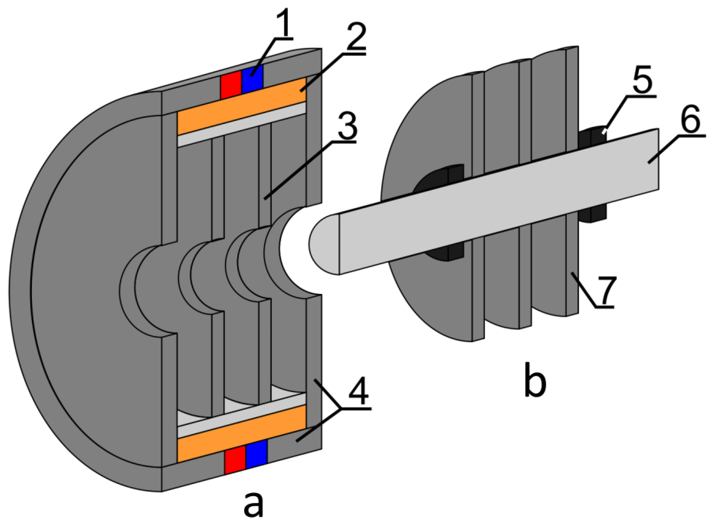
An MR clutch is a device that transmits torque by the shear stress of MR fluids from the driving shaft to driven shell; the MR fluid is located between the discs and the driven members [16,17]. In Figure 1, a schematic representation of an MR multidisc clutch is shown.
This article describes an MR multidisc clutch. The number of clutch discs N is connected to the discs of the internal member (driven (moving) member) (Figure 2). The total number of discs in the clutch is a sum of the number of discs of both members (driven and driving members), equal to:
Thereafter, the MR clutch is a mechanical device whose main element is the fluid, and the clutch torque is controlled by a magnetic field, so the MR design process is complex.
The design process considers the following calculations: magnetic field calculations, mechanical calculations and fluid dynamics calculations. The main parameter of the MR clutch is the clutching torque, , which is the maximum value of the torque which can be transmitted by the clutch. The clutching torque, , results from shear stress, , in the MR fluid and the active surface S, which depends on the geometric parameters of the clutch (Figure 2). The shear stress, , depends on the magnetic field and this relation is described by the Bingham model:
where is the shear stress, is the stress caused by the applied magnetic field B, is the plastic viscosity and is the shear strain. Equation (2) is of fundamental importance since one of the addends links the mechanical yield strength to the magnetic induction field which, in turn, is closely linked to the electric current necessary to generate the magnetic field [18,19,20].
The first stage of design calculations is the magnetic field calculations. These calculations are necessary for the design process. The magnetic field distribution in the clutch and the geometrical parameters of the clutch can also be obtained as a result of the magnetic field calculations.
2.1. The Multi Disch MR Clutch Finite Element Model (FEM) for Magnetic Field Calculations
The magnetic field calculations play a specific role in the modeling and construction of an MR clutch, providing information about the magnetic field B in an MR fluid and determining the dominant component of the clutching torque, . The simulations were carried out with the Finite Element Method Magnetics (FEMM) calculation code, which is a finite element package for solving 2D planar and axisymmetric problems in low-frequency magnetics and electrostatics. For the simulation model, two different approximations were taken into consideration:
- Nonlinear BH characteristic of the magnetic materials forming the magnetic core.
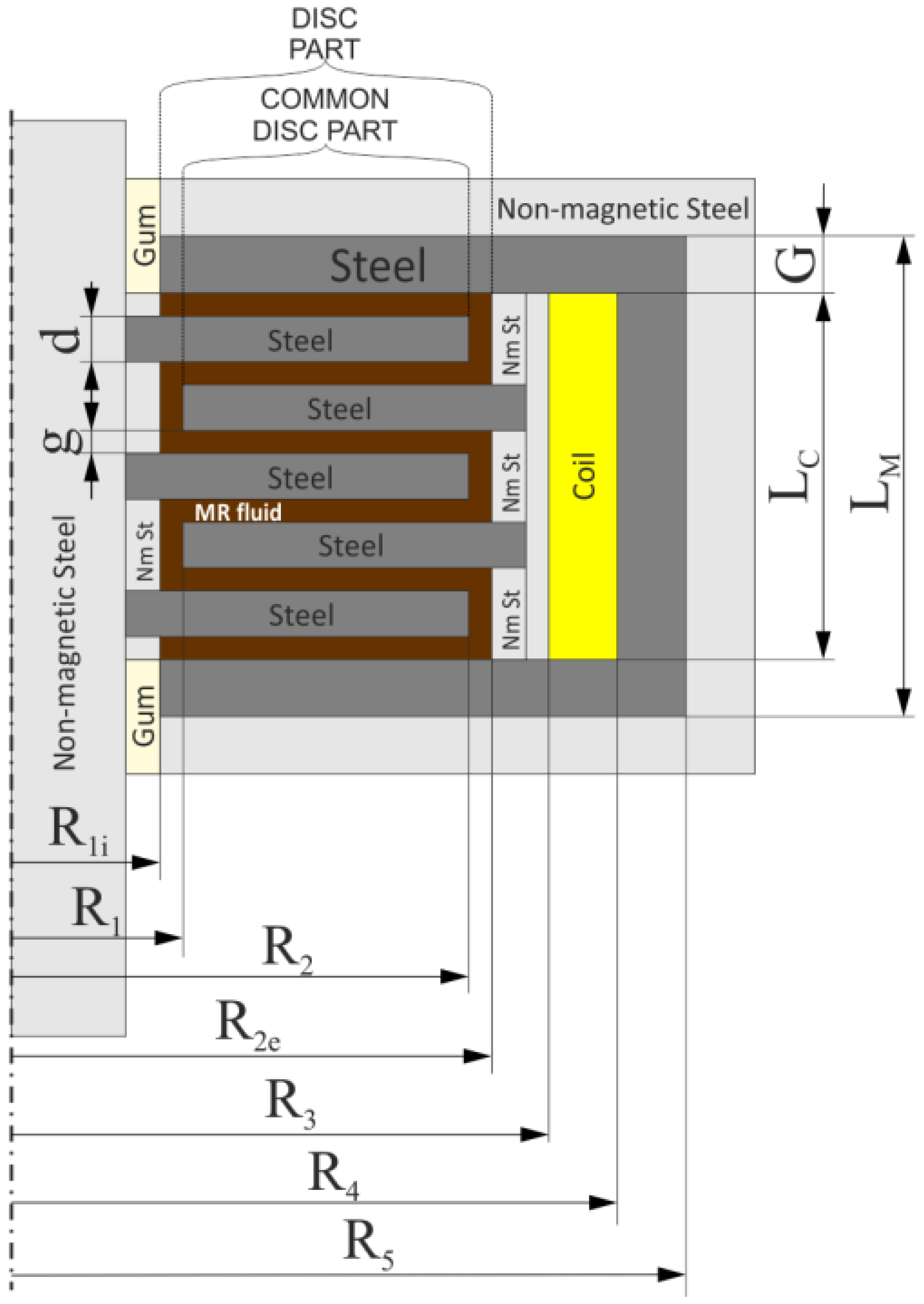
Since the MR clutch has an axial symmetry, a 2D FEM model can be used and half of the MR clutch cross-section is considered to be sufficient, as depicted in Figure 2.
Referring to Figure 2, is the average value of the inner discs radii, is the internal radius of the outer disc, is the external radius of the inner disc, is the external radius of the outer disc, is the internal radius of the coil, is the external radius of the coil, is the external radius of the magnetic circuit, d is the disc width, g is the MR fluid gap width and G is the yoke width.
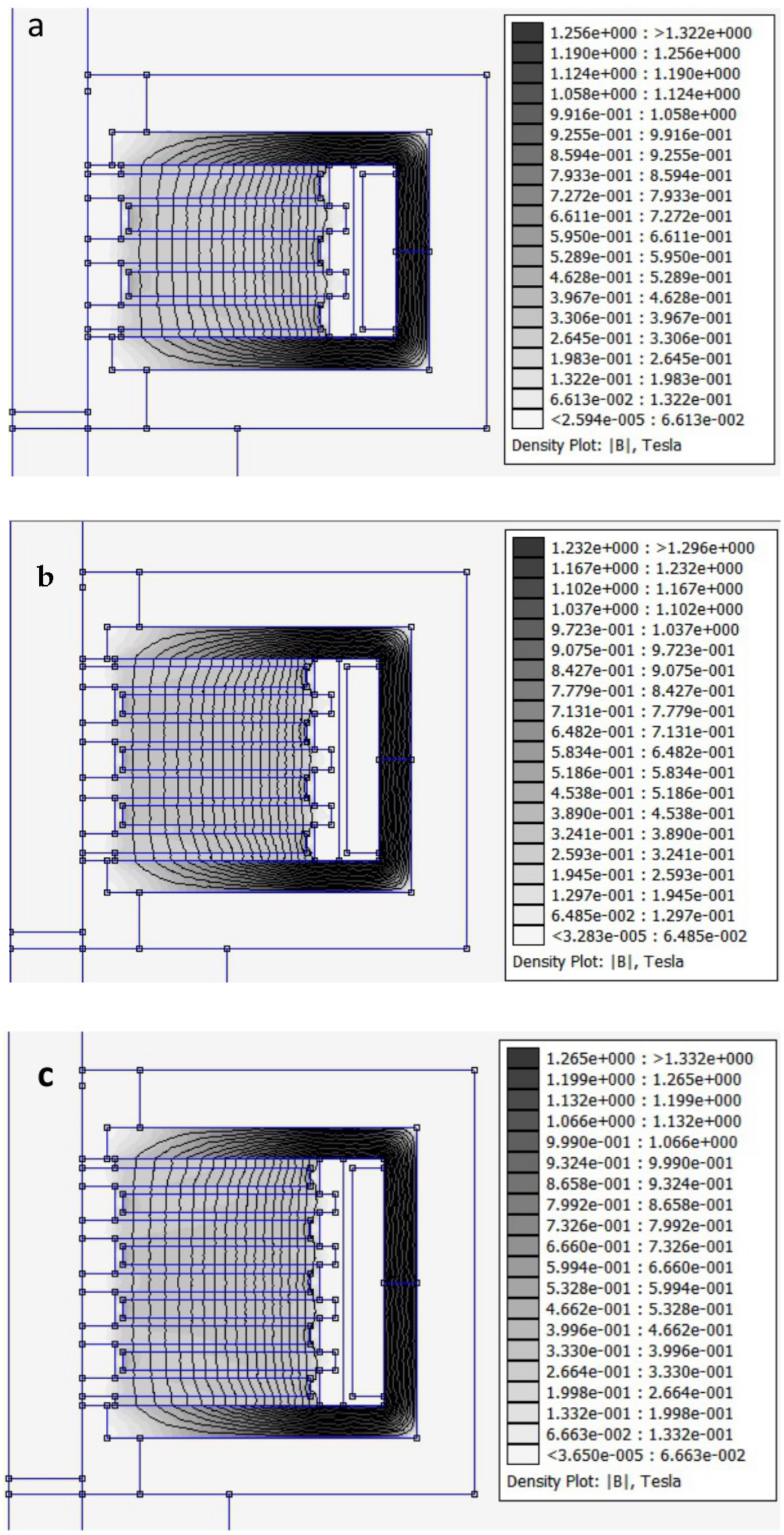
The simulations were carried out by varying the number of discs, N, in the range from 2 to 7 and, consequently, with d values varying from 2 mm to 5 mm.
In the FEM analysis of an MR clutch with linear BH characteristics for relative magnetic permittivity, values of and were used, respectively, for the MR fluid and steel.
The magnetic field distributions in the MR clutch for three different geometric configurations are reported in Figure 3.
2.2. Clutch Torque Calculation
In magnetic field control mode, starting from the magnetic field distribution and the MR clutch geometric parameters, the clutching torque is calculated according to the equation [7] given by:
where is the given torque, is the radial distribution of the normal component of the magnetic field, N is the number of primary member discs and is the yield shear stress caused by the magnetic field distribution (these data can be found in the MR fluid datasheets that describe their properties). In the next stage of the design, is calculated as a function of current, I, using Equation (3).
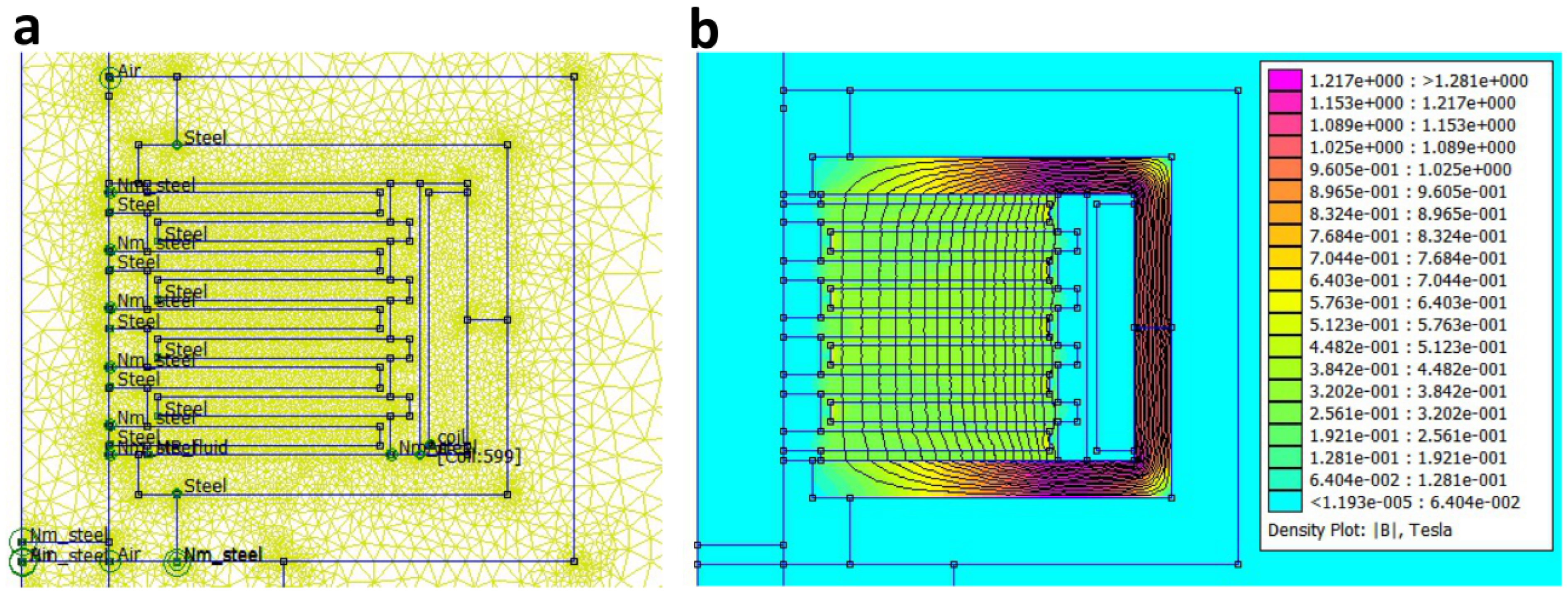
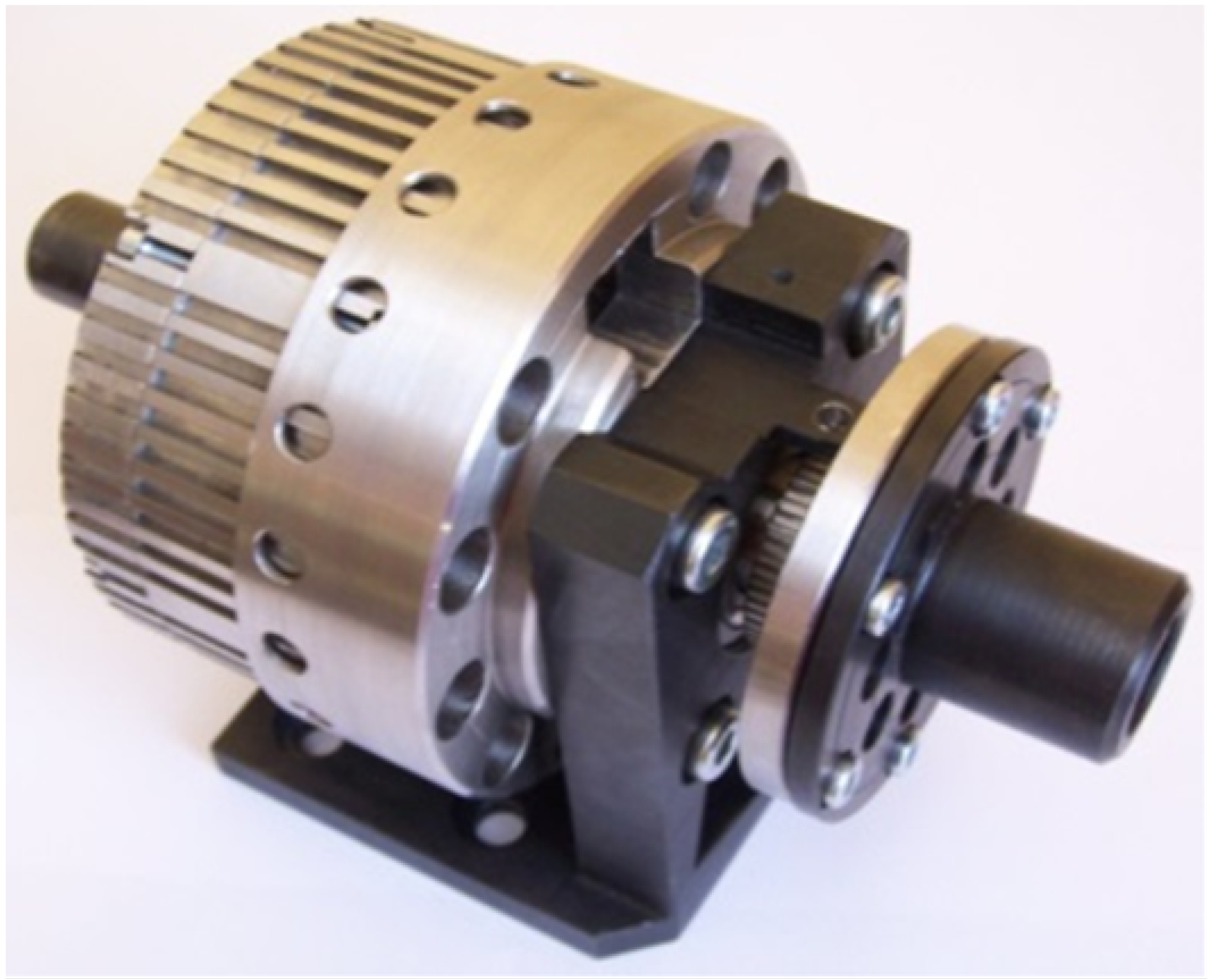
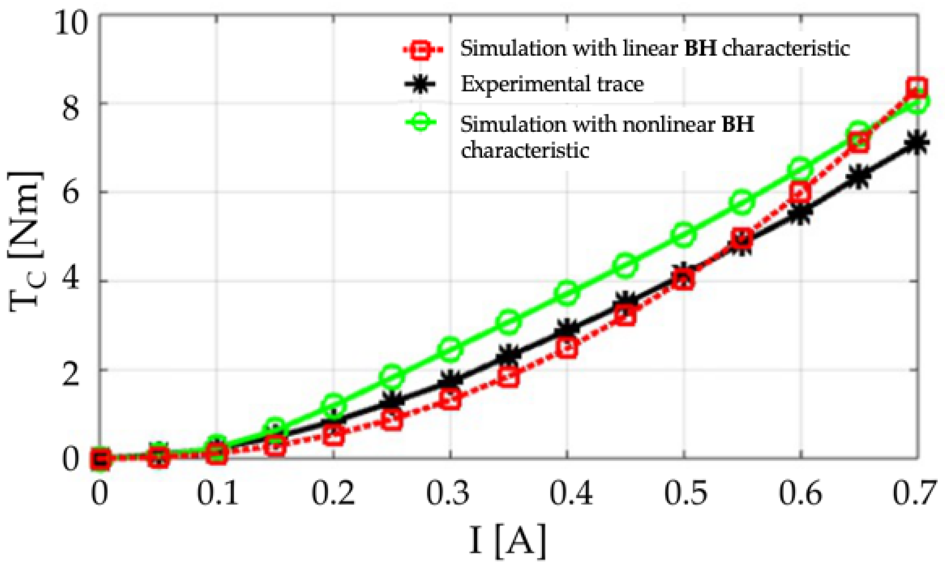
To obtain the torque transmission of the designed multi-plate MR clutch, the torque generated by the mechanical friction in the clutch was calculated using the torque modeling Equation (3). To obtain the exact value of the clutching torque determined on the basis of the real spatial distribution of the magnetic flux density, the FEM model was used. The simulation of the magnetic field inside the MR clutch with five discs using nonlinear BH characteristics is shown in Figure 4. The optimal configuration obtained by simulations is an MR clutch with five discs due to the fact that each disc has different properties, dimensions, geometrical proportions, masses, volumes and clutching torques. Using the magnetic field distribution inside the five-disc clutch for both the linear and nonlinear case and Equation (3), the versus steering current, I, traces were obtained.
The torque curves of the clutch were compared with a real five-disc MR clutch (Figure 5), which was designed and manufactured at the Department of Mechatronics at Silesian University of Technology. As shown in Figure 6, the data obtained with both calculation models (linear and non-linear) are in good agreement with the experimental data obtained by the realized clutch.
3. Clutch Control by Means of Magnetorheological Fluids
The viscosity of an MR fluid is changed by a magnetic field generated by a current-carrying coil and a permanent magnet so that the clutch generates a clutching torque TC (I = 0) without needing to supply the coil. The current I flowing along the coil can decrease (I−) or increase (I+) the magnetic field in the gaps with an MR fluid, which leads to a reduction in the clutching torque TC (I−) or an increase in the clutching torque TC (I+). Multi-disc magnetorheological clutches can satisfy dynamometrical functions regarding clutch safety, half-active elimination of rotary vibrations and a soft start-up system. MR fluids allow operation at a low control power in the absence of inertia and friction problems, such as in automotive, medical and mechanical devices. Compared to traditional electro-mechanical solutions, the use of MR technology offers some important advantages, namely sliding resistance fluid, power and stability. MR fluids exhibit a maximum flow resistance, measurable as the yield stress, of 50–100 KPa, corresponding to the application of a magnetic field of 150–250 KA/m [21,22]. MR fluids that are subjected to a magnetic field change instantly and the internal viscosity is reversed proportionally to the applied magnetic field. In the absence of an applied field, they exhibit, being magnetizable, a rheological behavior similar to Newtonian fluids, while following the application of a magnetic field, they develop a viscous resistance which depends on the intensity of the magnetic field [23,24,25].
3.1. Experimental Set-Up for MR Clutch Control Characterization
The base of the station was a universal mounting plate, designed to be able to mount all components of the measuring system regardless of the type of test (static and dynamic tests) and regardless of the type of tested clutch. The form of the test stand configured for determining static characteristics is shown in Figure 7.
- 1.
- Tested clutch.
- 2.
- DATAFLEX 22/20 torque meter.
- 3.
- FESTO DSR-16-180-P pneumatic rotary actuator to create the load moment for the clutch (static tests and low frequency pulsations).
- 4.
- FUMO VER-30H-20-6 powder brake (generation of adjustable braking torque).
- 5.
- Load in the form of an inertia disc (passive load).
- 6.
- Flexible backlash-free couplings RADEX-NC 25 EK.
- 7.
- Coupling connecting the actuator with the tested clutch.
- 8.
- Mounting plate.
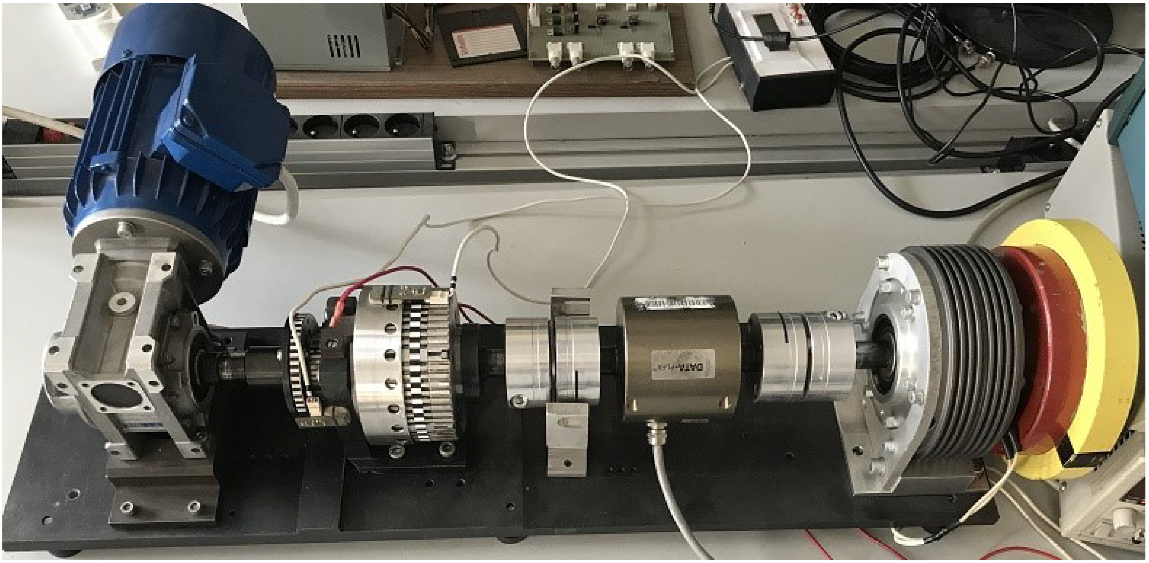
The laboratory set-up includes drive sources, the tested clutch, measuring elements, flexible couplings and load as shown in Figure 8.
The laboratory testing system allows measurements of:
- The electric circuit—coil voltage and current;
- The mechanical system—momentum coupling.
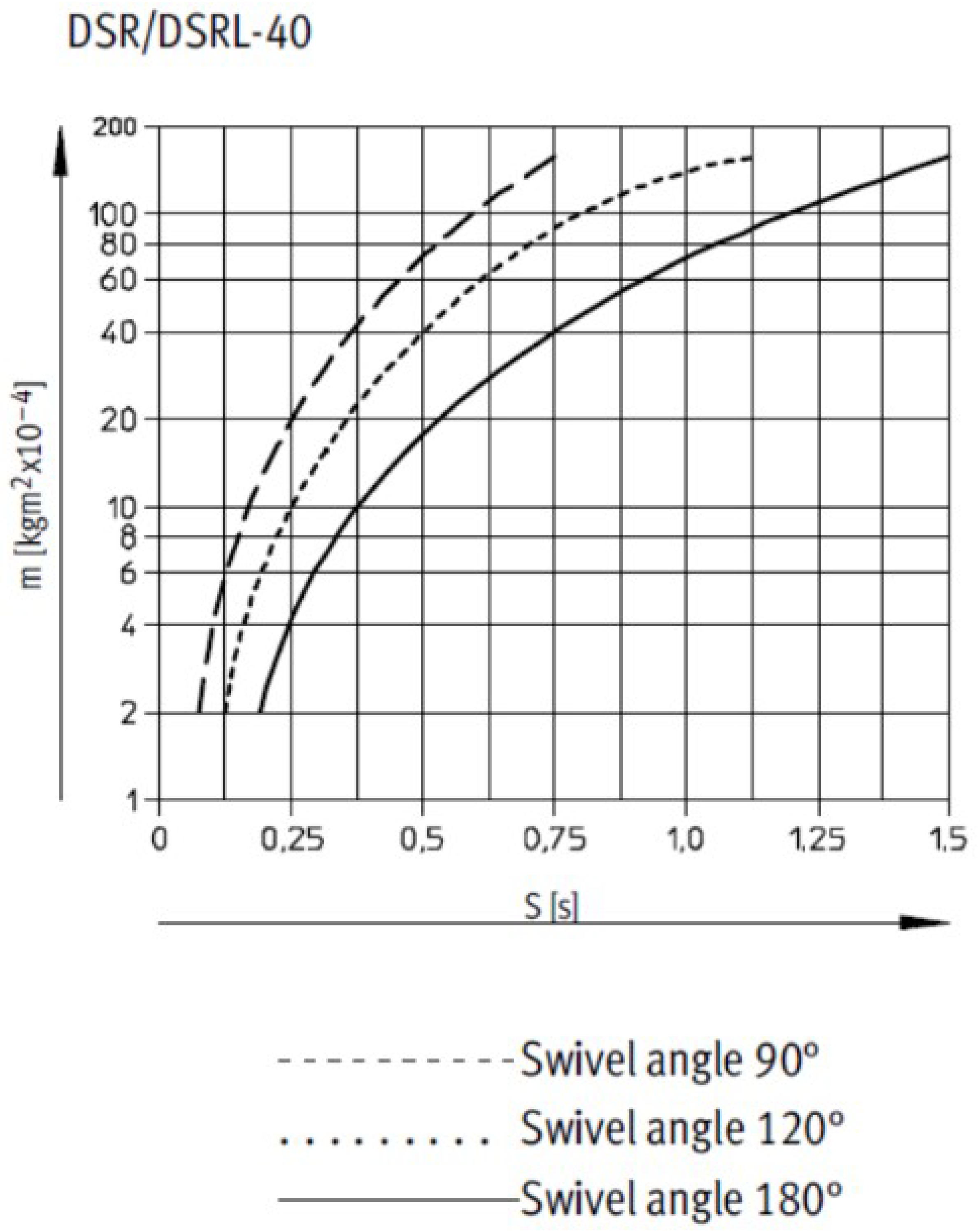
In static and dynamic tests at low frequencies, the FESTO DSR-16-180-P pneumatic rotary actuator was used as a forcing. In these semi-rotary drives, the force is directly transmitted to the drive shaft via a rotary vane. The swivel angle is infinitely adjustable from 0 to (see Figure 9). The adjustable stop system is separate from the rotary vane so that any forces which occur are absorbed by the stop blocks. The impacts are cushioned at the end positions by flexible plastic plates. The force is transmitted directly and backlash-free via a splined shaft, and the torque generated by the actuator is a linear function of the actuator supply pressure. According to the manufacturer’s data, for a pressure of 6 bar, the actuator generates a torque of 20 Nm.
When throttling the semi-rotary drives at swivelling speeds under /s, the drives must be operated at a pressure of at least 6 bar. A constant speed fluctuation of % is to be expected.
The power supply and control system have been designed for an electro-pneumatic system (rotary actuator and control solenoid valve) at the laboratories of the Department of Mechatronics at the Silesian University of Technology in Gliwice, Poland. The braking moment forcing in the station was carried out by a FUMO VER-30H-20-6 powder brake.
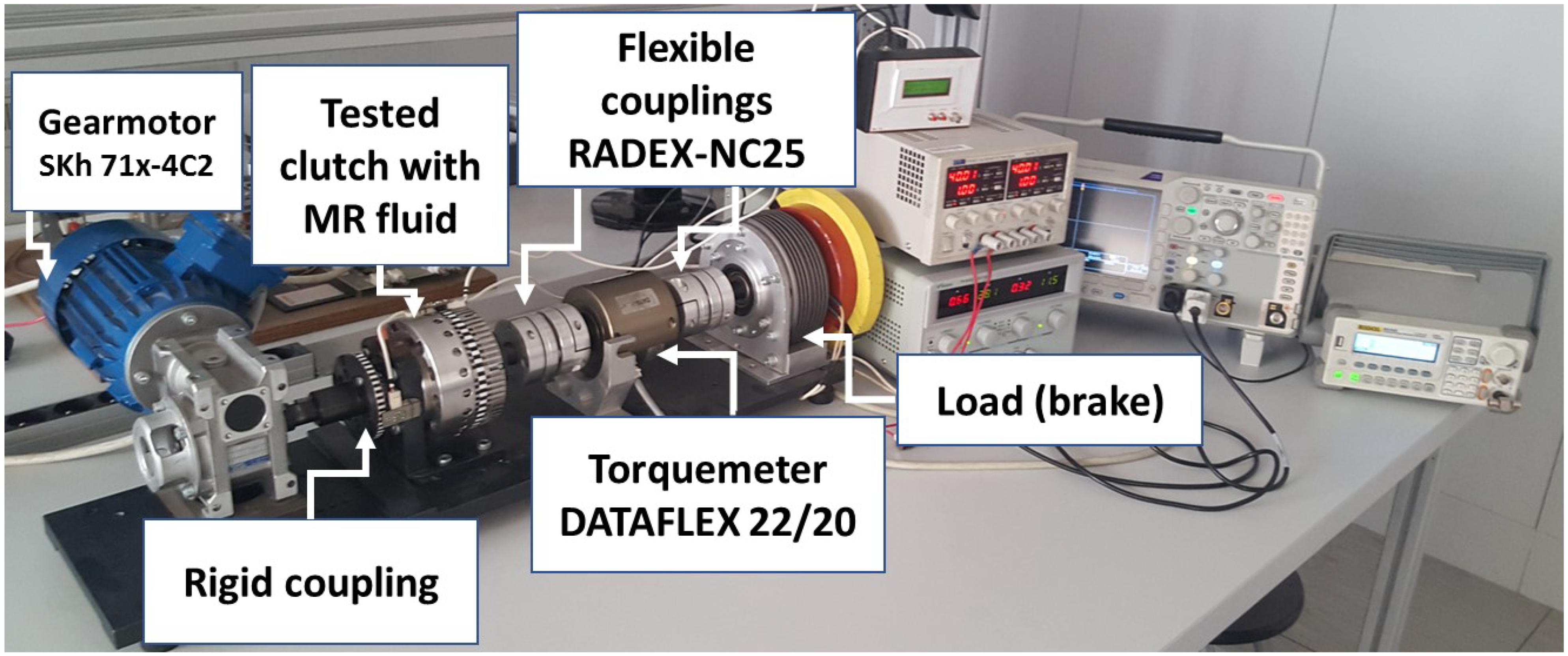
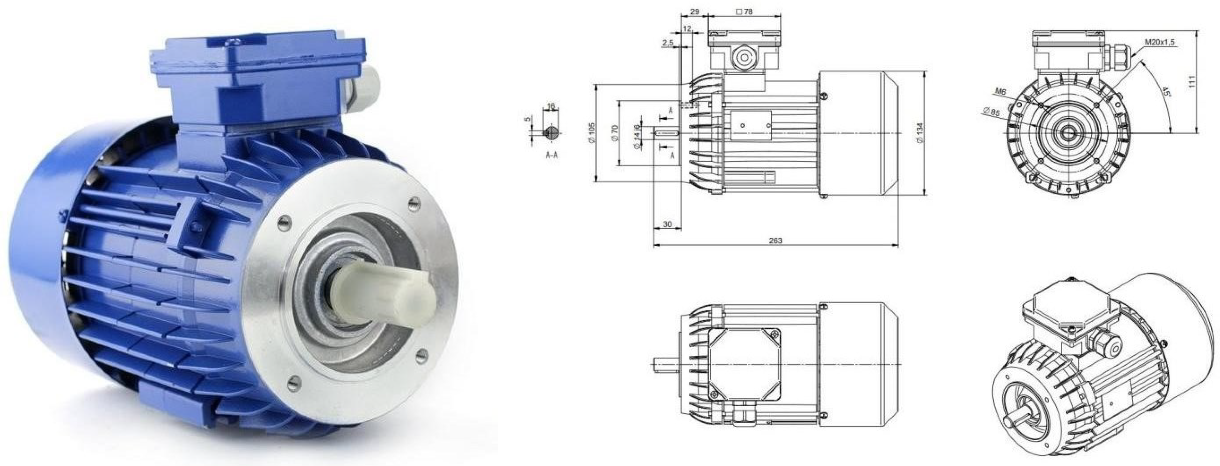
The driving torque was generated by a BESEL SKh 71X-4C2 three-phase induction motor shown in Figure 10. The load consists of a VER-30H-20-6 FUMO magnetic powder brake and an inertia disc (passive load).
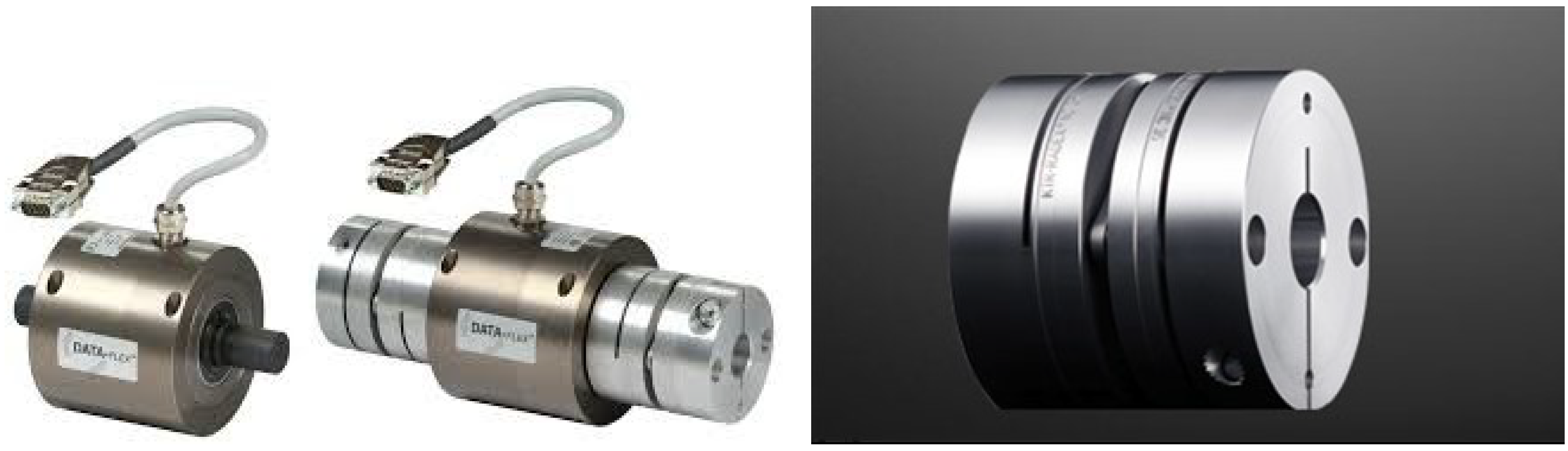
In order to supply the coil of the magnetorheological clutch and the electromagnetic brake with electricity, CPX400D and Tektronix PWS2323 linear DC power supplies were used, which are able to control the coupling torque generated by the clutch and the braking torque generated by the brake. The measurement of the coupling torque and namely the moment transmitted from the active to the passive element was carried out using a KTR DATAFLEX 22/20 torquemeter with a rated torque TKN of −20 to 20 Nm, depicted in Figure 11. The basic operational parameters of the torquemeter are summarized in Table 1. The torque measuring shaft contains an integrated speed measurement combined with a steel lamina coupling. The complete system is formed by a torsional stiff and a double-cardanic coupling with an integrated measuring shaft. When torque is generated, the torsion shaft twists at an angle of 45 with respect to the longitudinal axis. A wire strain gauge is flatly bonded with the shaft following the deformation of the torsion shaft. The wire strain gauge consists of two unfolded wires arranged in a way that, upon the influence of torque, one of the two wires lengthens, thus changing its electrical resistance. A coil pair built coaxially serves as the power supply of the rotating electronics assembly and wire strain gauge. The fixed coil induces a voltage in the rotating coil, powering the rotating electronics assembly. In addition to torque measurement, each measuring shaft includes an integrated speed measurement. An encoder scans a code disk generating two speed signals, each with 720 pulses per revolution. Since two signals out of phase are generated, the torsional direction can be identified as well. To integrate a torque measuring shaft into the drive, it is mounted between the drive and the load so that the torque that is generated does not result in torsion in the shaft.
A Tektronix MDO3012 oscilloscope was used with the measurement probes (TPP0250 voltage probe and TCP202 current probe) to record the measurements of the transmitted torque, voltage and current of the coil.
The test system designed and constructed in this way allows to determine static and dynamic characteristics of the tested clutch with MR fluid.
3.2. Experimental Set-Up Modifications for Magnetorheological Coupling Measurements in the Dynamic State
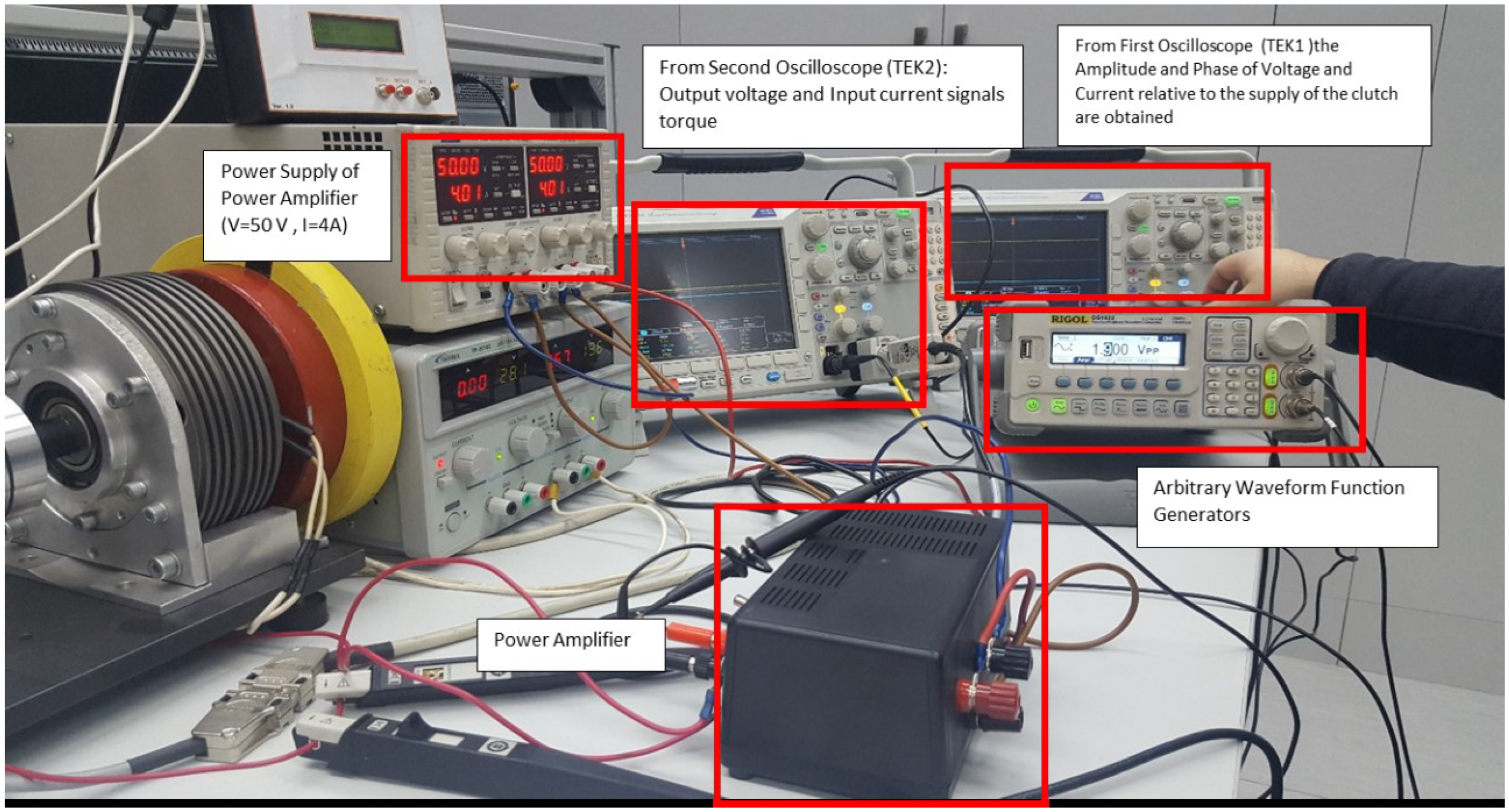
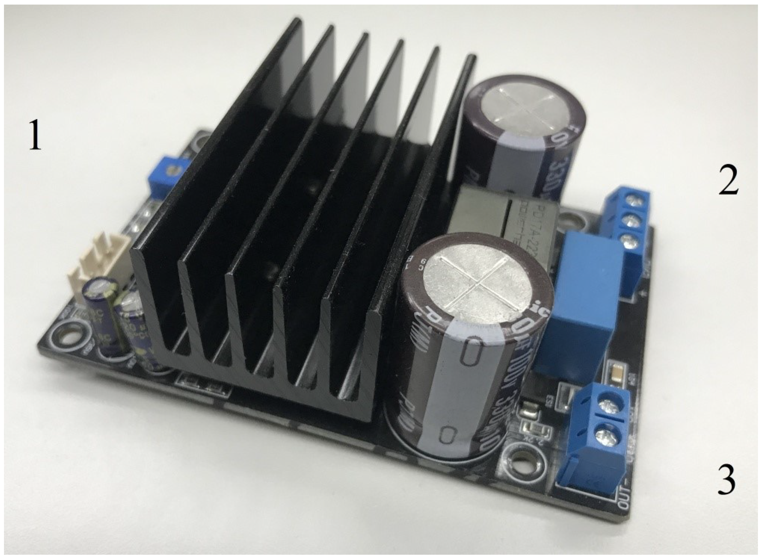
In order to perform measurements of the main parameters of the magnetorheological clutch operating in a dynamic regime, the experimental system was improved by adding a power amplifier module (Figure 12). A class D high power audio amplifier based on an IRS2092 Audio Amplifier module system was used.
The main parameters of the power amplifier module are:
- Symmetrical power supply voltage from +/− 40 V to +/− 60 V;
- Recommended supply voltage +/− 50 V;
- Frequency range up to 20 kHz;
- Output power 200 W;
- Maximum efficiency ;
- Maximum output current 8 A.
The power amplifier was placed in a casing (Figure 13), in which the power and output laboratory terminals were properly connected to the power connector and the output of the module. In addition, a toggle switch (on/off) was installed to enable/disable the amplifier output signal. A two-channel power supply was used in the laboratory to supply the amplifier module to obtain a symmetrical power supply. In turn, the module output was connected to the coil of the tested clutch.
The RIGOL DG1022 function generator was connected to the input connector of the power amplifier in order to supply a generated signal. This signal could be, e.g., sinusoidal, rectangular or triangular.
4. Laboratory Experiments Carried Out, Results and Clutch Control Model
The experiments were carried out by using the experimental system shown in Figure 12. In all investigations regarding the clutch control conducted in laboratory, LORD MRF-132DG fluid was used, which is a hydrocarbon-based magnetorheological (MR). In this paper, experimental tests were carried out in static and dynamic modes in order to evaluate the behaviour of the MR clutch in the time and frequency domains.
4.1. Experiments Conducted in Static Mode
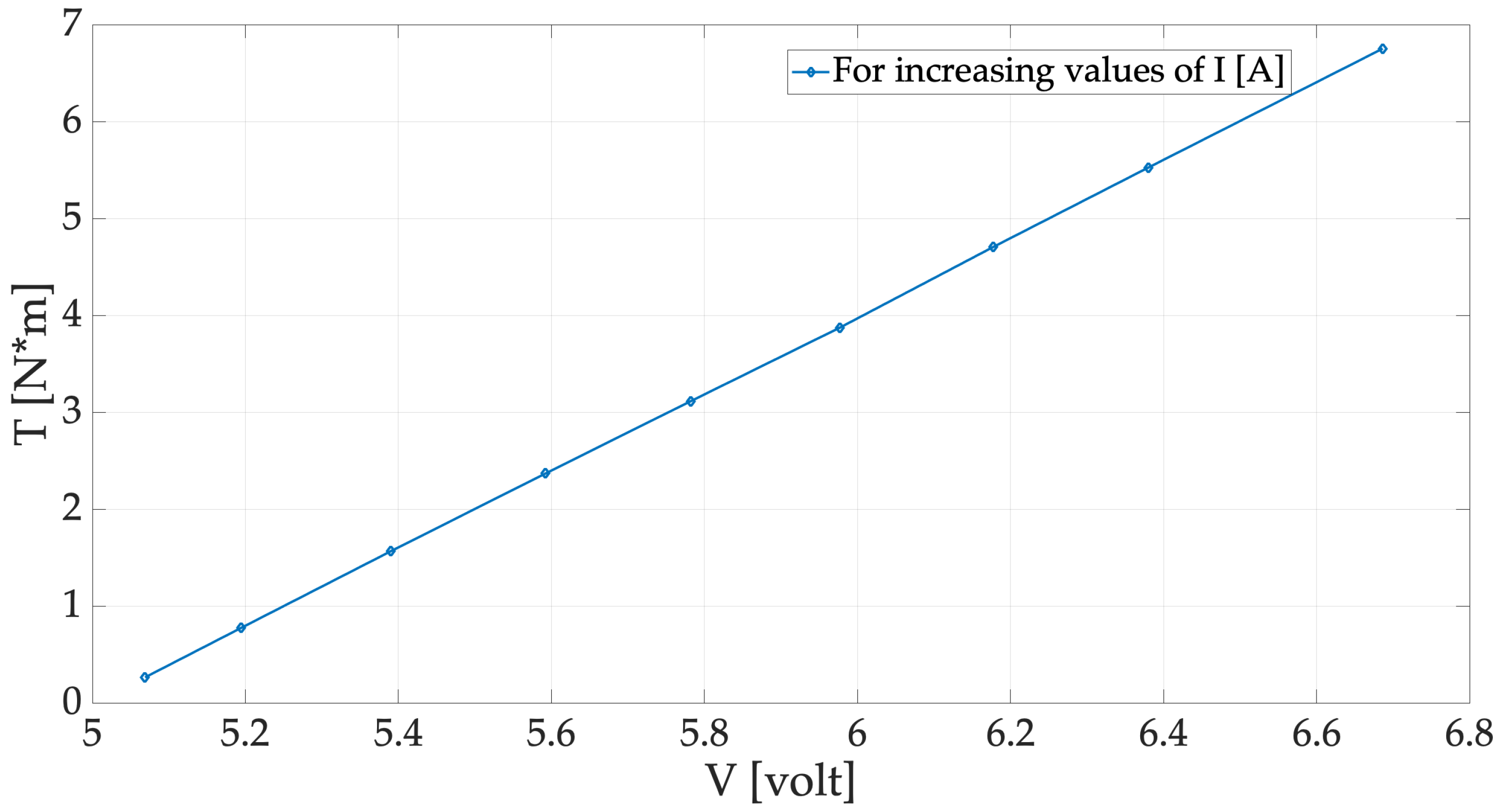
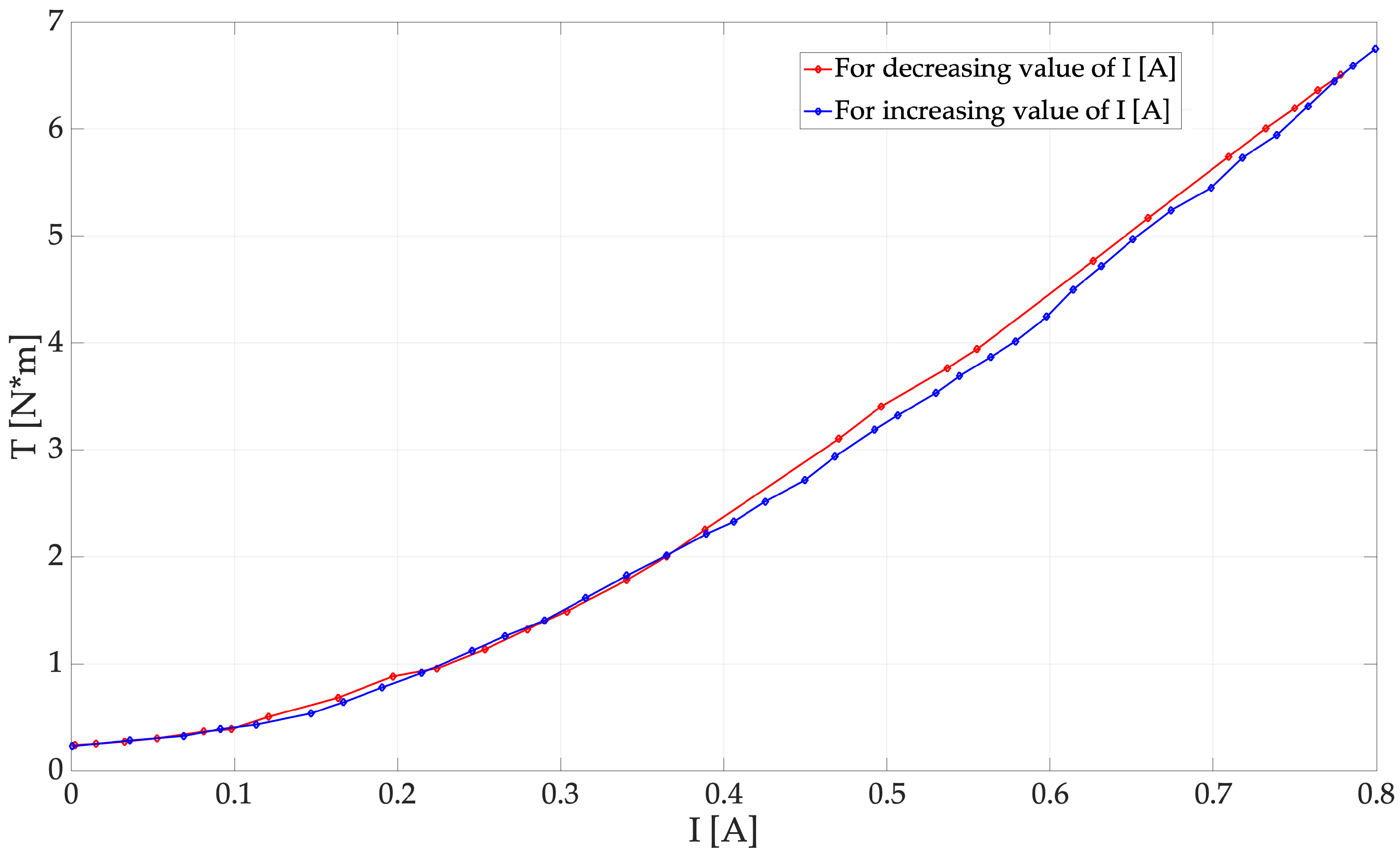
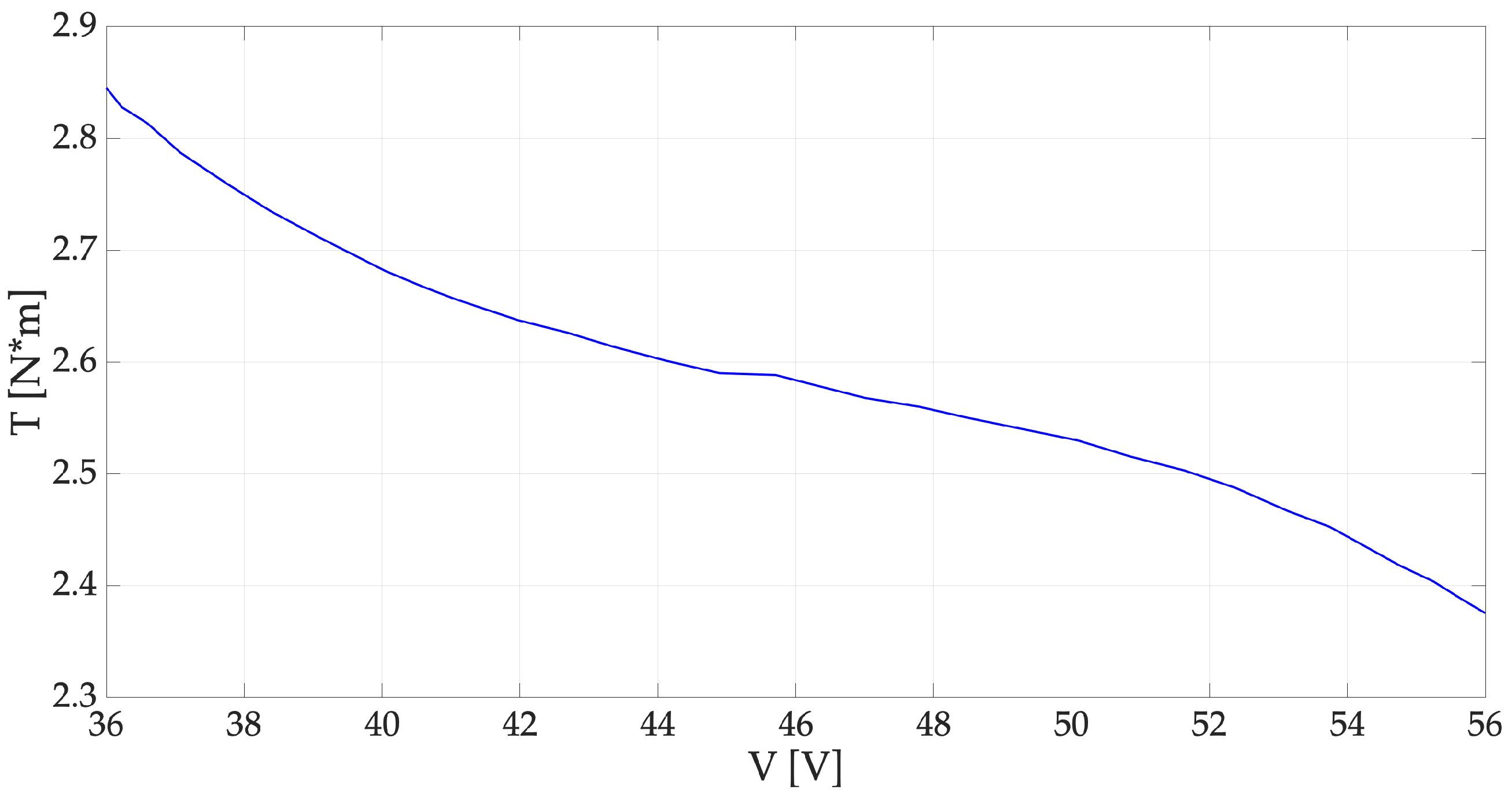
In the first set of experiments, an analysis of the steady-state characteristics of the MR clutch was conducted, applying increasing and decreasing values of current in the range of 0 to 0.8 A to the MR clutch. The experimental torque values obtained are reported in Figure 14 and Figure 15, showing, respectively, the dependence of torque T on the voltage and the current.
The obtained experimental dependence between torque and voltage could be summarized by means of the simple Equation (4).
The MR fluid brake is driven by a speed-controlled motor and the current torque is measured by a torque transducer while the coil current is controlled by a power supply. These simple experiments have demonstrated that by increasing or decreasing the value of the applied voltage or current, the transmitted clutch torque value is increased or decreased, thus obtaining a good clutch control.
4.2. Experiments Conducted in Dynamic Mode
In the second set of experiments, measurements of torque were conducted for voltage and current values varying in amplitude and frequency. The waveform generator Rigol dg1022 generates variable signals at different amplitudes and frequencies, so these waveforms were used for clutch control after the amplification obtained by the power amplifier. In the first oscilloscope, named TEK1 in Figure 12, the clutch control waveforms were recorded and visualized, while the second oscilloscope, named TEK2 in Figure 12, recorded and visualized the clutch output voltage values which depend on the measured torque.
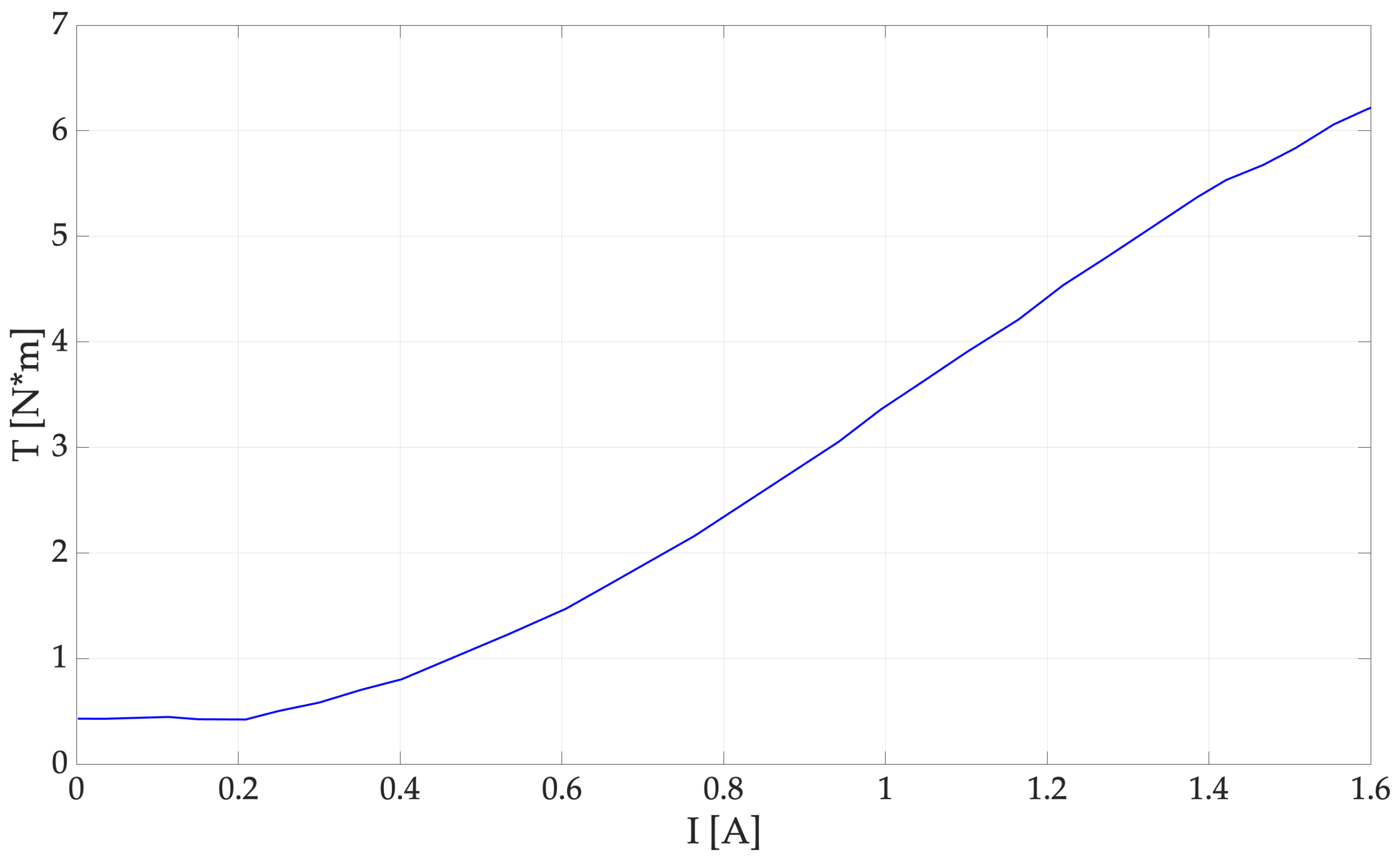
Furthermore, the torque creates a dependency between the currents and voltages measured at the output of clutch system; therefore, it is important to derive experimentally the dependence between torque and current as well as between torque and voltage at different frequencies. In Figure 16 and Figure 17, these dependencies obtained experimentally are reported.
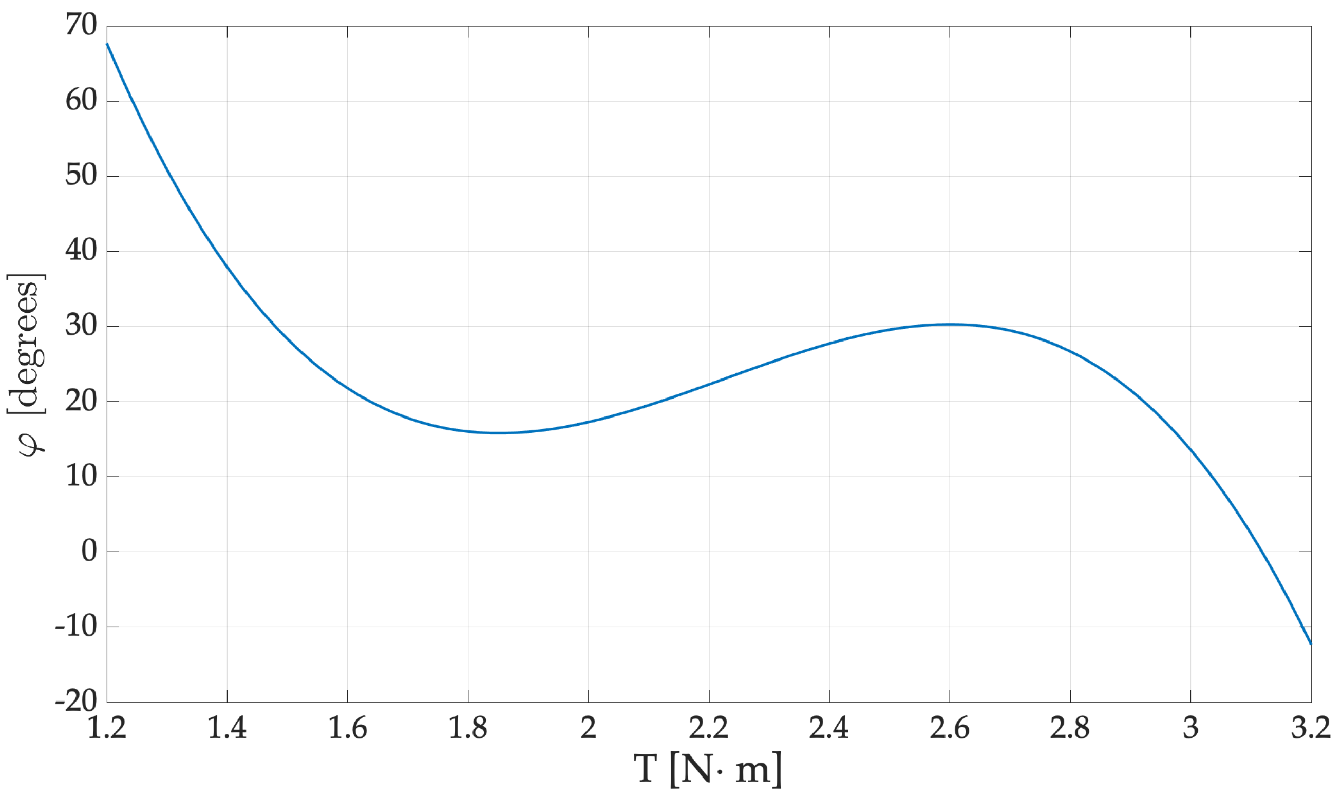
Since the torque depends on both the output current and the output voltage, then surely the torque can be characterized by its dependence on the phase shift, , between current and voltage. This dependence obtained experimentally is reported in Figure 18.
4.3. Clutch Control Model and Results
The input values, such as voltages and currents of the MR clutch, allow the transmitted torque to be controlled. In the previous subsection, the torque creates a dependency between the current and voltage measured at the output and it was also demonstrated that the torque can be characterized by its dependence on the phase shift, , between current and voltage.
By means of extensive experimental campaigns, these relations are explicated. Furthermore, applying the least-squares method by using polynomial, sinusoidal orthogonal functions and Gaussian radial basis functions [26,27] as base functions, the analytical expressions of these functional dependencies are obtained.
More specifically, the relationship between the clutch control voltage and current is represented by the following equation:
Instead the phase shift, , between the aforementioned voltage and current is represented by the equation:
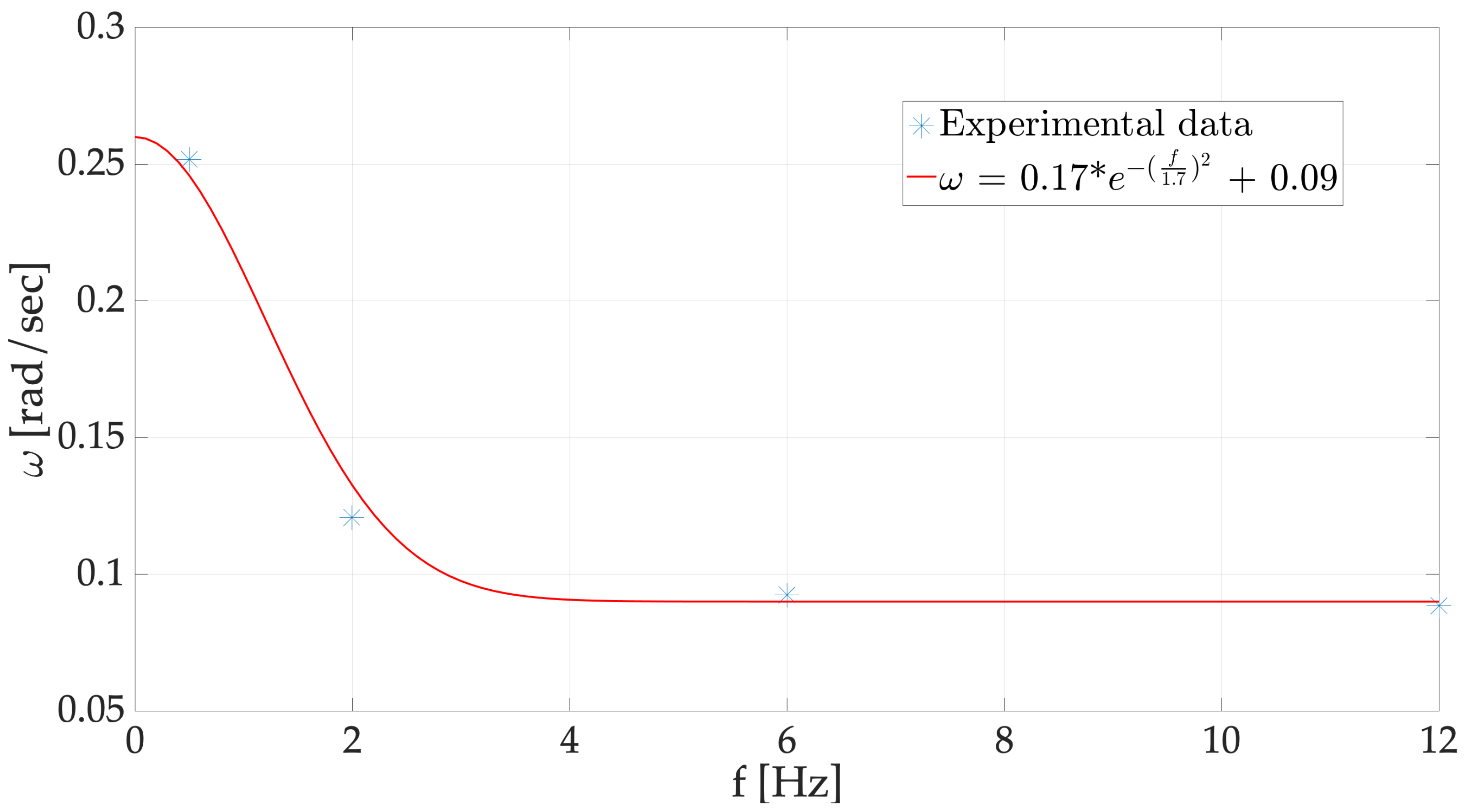
Furthermore, is related to the work frequency, f, by the equation:
where the parameters and depend on the clutch mechanical characteristics, on the physico-chemical properties of the MR and on the frequency, f, while the parameters and D depend on the clutch mechanical characteristics and the physico-chemical properties of the magnetorheological fluid. The dependency between and the working frequency f relating to the realized MR is shown in Figure 19.
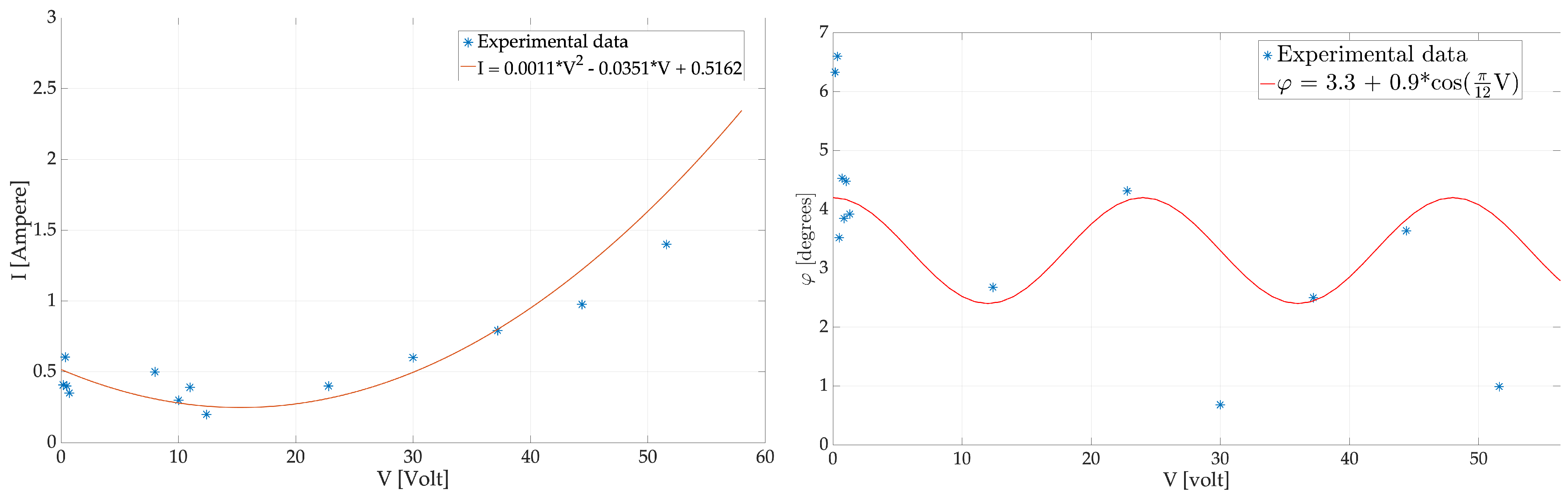
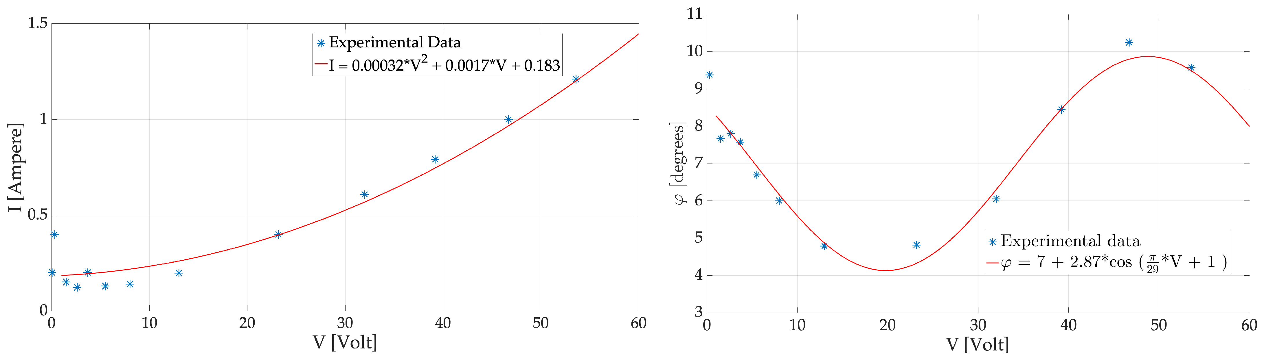
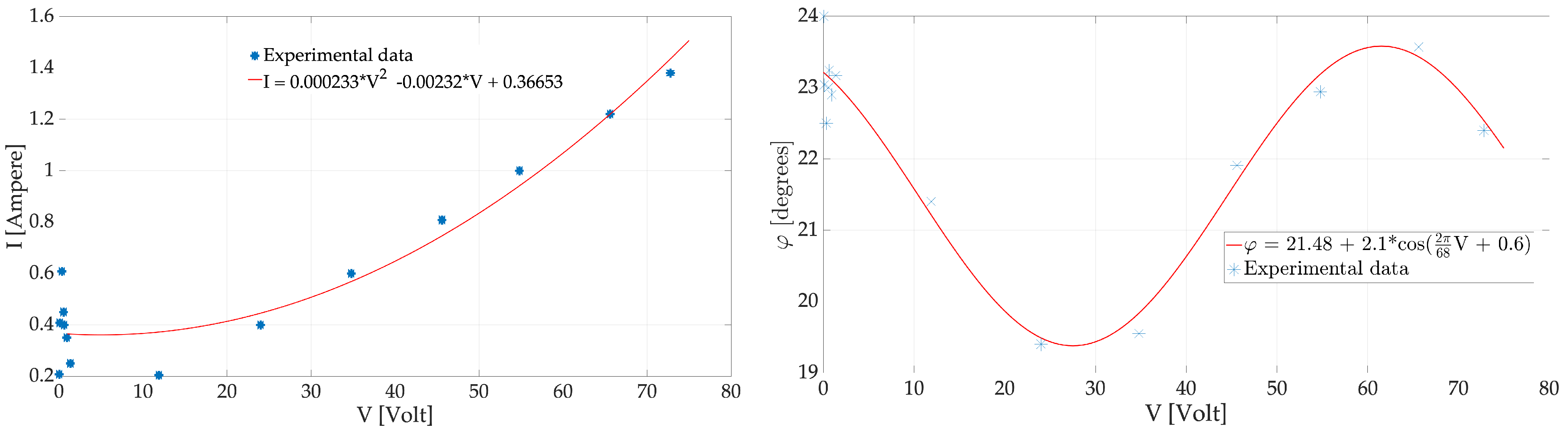
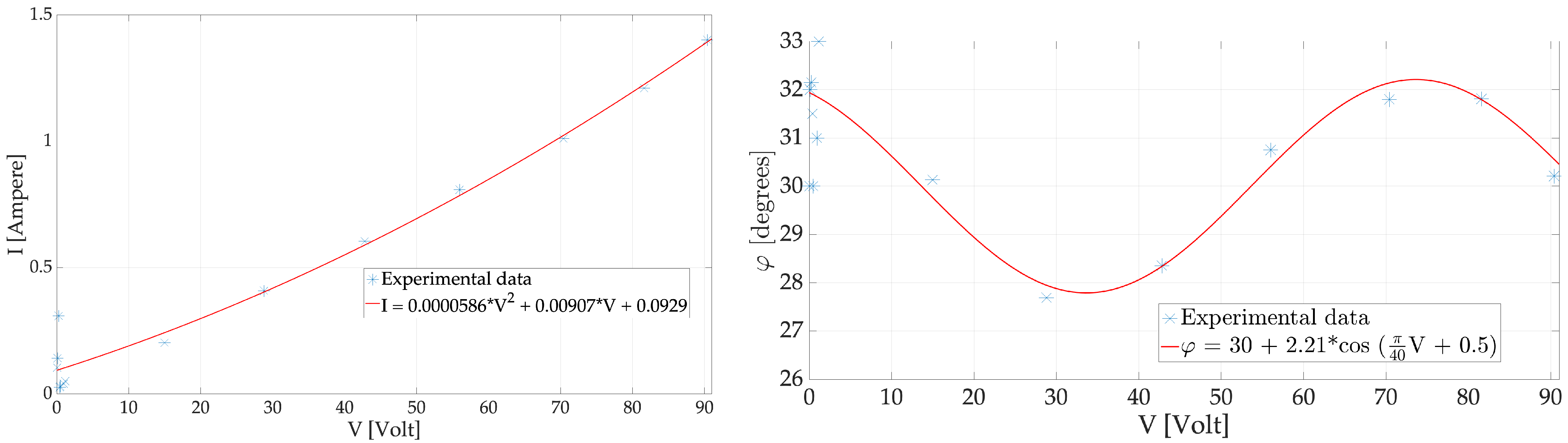
In Figure 20, Figure 21, Figure 22 and Figure 23, the dependencies between the currents and voltages and the phases shift as a function of voltage relating to the realized MR clutch at working frequencies of 0.5 Hz, 2 Hz, 6 Hz and 12 Hz, obtained both experimentally and by Equations (5) and (6), are reported.
The achieved results shown in Figure 20, Figure 21, Figure 22 and Figure 23 demonstrate that the analytical models are in good agreement with the experimental data, exhibiting an overall error of about 7%. Furthermore, Equations (5)–(7) can be used as design formulas in order to achieve the efficient and accurate control of an MR clutch.
5. Conclusions
In this paper, the characterization of a new clutch control strategy by means of a magnetorheological fluid is investigated.
On comparison with previous studies, the novelty of this work is presented in the experimental characterization of a real clutch characterized in static and dynamic modes in a laboratory. The performance measurements have been validated by the proposed mathematical model and algorithms. More specifically, the static and dynamic characteristics of the designed MR clutch have been determined in the laboratory. Furthermore, the analytical relationships describing the connection between control quantities and controlled quantities have been determined. The achieved results report that the analytical models are in good agreement with the experimental data, showing an overall error of about 7%.
Author Contributions
G.L.S., P.K. and G.C. contributed equally. All authors have read and agreed to the published version of the manuscript.
Funding
This research received no external funding.
Data Availability Statement
Not applicable.
Acknowledgments
The authors wish to thank Agata Abela for their contribution and support.
Conflicts of Interest
The authors declare no conflict of interest.
References
- George, L.K.; Tamilarasan, N.; Thirumalini, S. Design and analysis of magneto rheological fluid brake for an all terrain vehicle. In IOP Conference Series: Materials Science and Engineering, Proceedings of the International Conference on Advances in Materials and Manufacturing Applications (IConAMMA-2017), Bengaluru, India, 17–19 August 2017; IOP Publishing: Bristol, UK, 2018; Volume 310, p. 012127. [Google Scholar]
- Rahim, S.L.; Zulkifli, S.M.; Abu Bakar, M.H. Nonlinear Control of a Magneto-Rheological Fluid Electrohydraulic Positioning System. In Progress in Engineering Technology III; Springer: Berlin/Heidelberg, Germany, 2021; pp. 9–17. [Google Scholar]
- Kim, D.H.; Kim, J.W.; Choi, S.B. Design and Modeling of Energy Efficient Dual Clutch Transmission With Ball-Ramp Self-Energizing Mechanism. IEEE Trans. Veh. Technol. 2020, 69, 2525–2536. [Google Scholar] [CrossRef]
- Škugor, B.; Deur, J.; Ivanović, V. E-Clutch Torque Control Including Compensation of Thermal Expansion Effects. IEEE Trans. Veh. Technol. 2020, 69, 246–257. [Google Scholar] [CrossRef]
- Hua, D.; Liu, X.; Li, Z.; Fracz, P.; Hnydiuk-Stefan, A.; Li, Z. A Review on Structural Configurations of Magnetorheological Fluid Based Devices Reported in 2018-2020. Front. Mater. 2021, 8, 24. [Google Scholar] [CrossRef]
- Thakur, M.K.; Sarkar, C. Development and performance analysis of a Magnetorheological fluid Clutch. In Proceedings of the COMSOL Conference, Boston, MA, USA, 3–5 October 2018. [Google Scholar]
- Kielan, P.; Pilch, Z. Comparison of properties of electromagnetic clutches with ferromagnetic powder and magnetorheological fluid for low frequency control signals. In Proceedings of the 2016 13th Selected Issues of Electrical Engineering and Electronics (WZEE), Rzeszow, Poland, 4–8 May 2016; pp. 1–6. [Google Scholar]
- Fernández, M.A.; Chang, J.Y.J. A study of factors affecting torque transmission in permanent magnet-based magnetorheological fluid clutch. Smart Mater. Struct. 2021, 30, 065024. [Google Scholar] [CrossRef]
- Zhang, H.; Du, H.; Sun, S.; Li, W.; Wang, Y. Design and Analysis of a Novel Magnetorheological Fluid Dual Clutch for Electric Vehicle Transmission; Technical report, SAE Technical Paper; Tohoku University: Miyagi, Japan, 2019. [Google Scholar]
- Zhou, H.; Zhao, W.; Zhang, H.; Wang, Y.; Wu, X.; Sun, Z. Magnetorheological seal: A review. Int. J. Appl. Electromagn. Mech. 2020, 62, 763–786. [Google Scholar] [CrossRef]
- Jung, S.; Choi, S.B.; Kim, J.; Ko, Y.; Lee, H. Adaptive Feed-Forward Control of the Clutch Filling Phase for Wet Dual Clutch Transmission. IEEE Trans. Veh. Technol. 2020, 69, 9577–9588. [Google Scholar] [CrossRef]
- Wang, S.; Liu, Y.; Cai, T. Clutch Control Strategy of Driving Mode Transition for P2 Hybrid Electric Vehicle. In IOP Conference Series: Materials Science and Engineering, Proceedings of the 2018 4th International Conference on Mechanical Engineering and Automation Science (ICMEAS 2018), Beijing, China, 12–14 October 2018; IOP Publishing: Bristol, UK, 2019; Volume 470, p. 012003. [Google Scholar]
- Wu, M. Sliding Mode Control of A Dry-Type Two-Speed Dual Clutch Transmission for An Electric Vehicle During Optimal Power Transmission Process in Torque Phase. In Proceedings of the 2018 IEEE Intelligent Vehicles Symposium (IV), Changshu, China, 26–30 June 2018; pp. 1968–1975. [Google Scholar]
- Guo, J.; Zhang, Y. Adaptive Starting Control Strategy for Hybrid Electric Vehicles Equipped with a Wet Dual-Clutch Transmission. Actuators 2023, 12, 123. [Google Scholar] [CrossRef]
- Wu, S.; Zhu, E.; Ren, H.; Liu, Z.; Li, J. Study on control strategy of clutch engagement based on fuzzy control during vehicle starting. In Proceedings of the 2009 WRI World Congress on Computer Science and Information Engineering, Los Angeles, CA, USA, 31 March–2 April 2009; Volume 5, pp. 82–86. [Google Scholar]
- Huang, J.; Chen, X.; Zhong, L. Analysis and testing of MR shear transmission driven by SMA spring. Adv. Mater. Sci. Eng. 2013, 2013, 307207. [Google Scholar] [CrossRef]
- Elzaghir, W.; Zhang, Y.; Natarajan, N.; Massey, F.; Mi, C.C. Model Reference Adaptive Control for Hybrid Electric Vehicle With Dual Clutch Transmission Configurations. IEEE Trans. Veh. Technol. 2018, 67, 991–999. [Google Scholar] [CrossRef]
- Yang, Y.; Li, L.; Chen, G. Static yield stress of ferrofluid-based magnetorheological fluids. Rheol. Acta 2009, 48, 457–466. [Google Scholar] [CrossRef]
- Han, W. Minimization principles for elliptic hemivariational inequalities. Nonlinear Anal. Real World Appl. 2020, 54, 103114. [Google Scholar] [CrossRef]
- Guo, C.w.; Chen, F.; Meng, Q.r.; Dong, Z.x. Yield shear stress model of magnetorheological fluids based on exponential distribution. J. Magn. Magn. Mater. 2014, 360, 174–177. [Google Scholar] [CrossRef]
- Utami, D.; Mazlan, S.A.; Imaduddin, F.; Nordin, N.A.; Bahiuddin, I.; Aziz, A.; Aishah, S.; Mohamad, N.; Choi, S.B. Material characterization of a magnetorheological fluid subjected to long-term operation in damper. Materials 2018, 11, 2195. [Google Scholar] [CrossRef] [PubMed]
- Gopinath, B.; Sathishkumar, G.; Karthik, P.; Charles, M.M.; Ashok, K.; Ibrahim, M.; Akheel, M.M. A systematic study of the impact of additives on structural and mechanical properties of magnetorheological fluids. Mater. Today Proc. 2021, 37, 1721–1728. [Google Scholar] [CrossRef]
- Kowol, P.; Szczygieł, M.; Lo Sciuto, G.; Capizzi, G. Modeling of Magnetorheological Fluids Relative Magnetic Permeability by using a Neural Network approach. In Proceedings of the 2020 IEEE 20th Mediterranean Electrotechnical Conference (MELECON), Palermo, Italy, 16–18 June 2020; pp. 25–28. [Google Scholar]
- Asiaban, R.; Khajehsaeid, H.; Ghobadi, E.; Jabbari, M. New magneto-rheological fluids with high stability: Experimental study and constitutive modelling. Polym. Test. 2020, 87, 106512. [Google Scholar] [CrossRef]
- Kumar, J.S.; Paul, P.S.; Raghunathan, G.; Alex, D.G. A review of challenges and solutions in the preparation and use of magnetorheological fluids. Int. J. Mech. Mater. Eng. 2019, 14, 13. [Google Scholar] [CrossRef]
- Pal, M. Numerical Analysis for Scientists and Engineers: Theory and C Programs, Alpha Science; Alpha Science: Oxford, UK, 2007. [Google Scholar]
- Gupta, M.; Jin, L.; Homma, N. Static and Dynamic Neural Networks: From Fundamentals to Advanced Theory; John Wiley & Sons: Hoboken, NJ, USA, 2004. [Google Scholar]
Figure 1.
Structure of a multidisc MR clutch: (a) housing (driving member) 1—permanent magnet, 2—coil, 3—disc of driving member, 4—yoke of magnetic circuit, (b) rotor (driven member): 5—bearings, 6—shaft, 7—disc of driven member.
Figure 1.
Structure of a multidisc MR clutch: (a) housing (driving member) 1—permanent magnet, 2—coil, 3—disc of driving member, 4—yoke of magnetic circuit, (b) rotor (driven member): 5—bearings, 6—shaft, 7—disc of driven member.

Figure 2.
Axisymmetric cross-section of an MR clutch with geometric parameters: general scheme of a magnetic field model.
Figure 2.
Axisymmetric cross-section of an MR clutch with geometric parameters: general scheme of a magnetic field model.

Figure 3.
Magnetic field distributions in the MR clutch for three different geometric configurations: (a) N = 3, d = 3 mm, I = 0.7 A, (b) N = 4, d = 2.5 mm, I = 0.7 A, (c) N = 5, d = 2 mm, I = 0.7 A.
Figure 3.
Magnetic field distributions in the MR clutch for three different geometric configurations: (a) N = 3, d = 3 mm, I = 0.7 A, (b) N = 4, d = 2.5 mm, I = 0.7 A, (c) N = 5, d = 2 mm, I = 0.7 A.

Figure 4.
(a) FEMmodel for the five-disc MR clutch made in FEMM software, (b) magnetic field distribution obtained as a result of FEM calculations.
Figure 4.
(a) FEMmodel for the five-disc MR clutch made in FEMM software, (b) magnetic field distribution obtained as a result of FEM calculations.

Figure 5.
The five-disc MR clutch designed and realized in the laboratory.

Figure 6.
Clutch torque versus steering current I for FEM “linear” calculations, experiment and FEM “nonlinear” calculations.
Figure 6.
Clutch torque versus steering current I for FEM “linear” calculations, experiment and FEM “nonlinear” calculations.

Figure 7.
The laboratory testing system created for static and dynamic MR clutch characterization.

Figure 8.
The test bench of the mechanical system.

Figure 9.
Relationship between the angle of rotation, time of movement and the mass moment of inertia which loads the pneumatic cylinder: mass moment of inertia, m, as a function of swivel time, S, and swivel angle.
Figure 9.
Relationship between the angle of rotation, time of movement and the mass moment of inertia which loads the pneumatic cylinder: mass moment of inertia, m, as a function of swivel time, S, and swivel angle.

Figure 10.
Besel SKh 71x-4C2 0.55 KW B14/2 Three-Phase Electric Motor.

Figure 11.
Used torque and its component: DataFlex torque measuring shaft and KTR RADEX NC 25 Dog Clutch Servo Motor Coupling.
Figure 11.
Used torque and its component: DataFlex torque measuring shaft and KTR RADEX NC 25 Dog Clutch Servo Motor Coupling.

Figure 12.
Experimental test setup of the MR clutch integrated for torque measurements conducted in the frequency domain.
Figure 12.
Experimental test setup of the MR clutch integrated for torque measurements conducted in the frequency domain.

Figure 13.
Class D poweraudio amplifier based on an IRS2092 Audio Amplifier module system.

Figure 14.
Dependenceof torque (T) on voltage (V) for different values of current in the range of 0 to 0.8 A.
Figure 14.
Dependenceof torque (T) on voltage (V) for different values of current in the range of 0 to 0.8 A.

Figure 15.
Dependenceof torque on current.

Figure 16.
Mean value of torque as a function of the maximum amplitude of the current in the dynamic state.
Figure 16.
Mean value of torque as a function of the maximum amplitude of the current in the dynamic state.

Figure 17.
Mean values of torque as a function of the maximum amplitude of the voltage in the dynamic state.
Figure 17.
Mean values of torque as a function of the maximum amplitude of the voltage in the dynamic state.

Figure 18.
Meanvalues of expressed in degrees as a function of the torque output in .

Figure 19.
Dependency between and the working frequency f related to the realized MR.

Figure 20.
On the (left): dependency between the current and the voltage related to the realized MR at a frequency of 0.5 Hz. On the (right): dependency between the phase shift and the voltage related to the realized MR at a frequency of 0.5 Hz.
Figure 20.
On the (left): dependency between the current and the voltage related to the realized MR at a frequency of 0.5 Hz. On the (right): dependency between the phase shift and the voltage related to the realized MR at a frequency of 0.5 Hz.

Figure 21.
On the (left): dependency between the current and the voltage related to the realized MR at a frequency of 2 Hz. On the (right): dependency between the phase shift and the voltage related to the realized MR at a frequency of 2 Hz.
Figure 21.
On the (left): dependency between the current and the voltage related to the realized MR at a frequency of 2 Hz. On the (right): dependency between the phase shift and the voltage related to the realized MR at a frequency of 2 Hz.

Figure 22.
On the (left): dependency between the current and the voltage related to the realized MR at a frequency of 6 Hz. On the (right): dependency between the phase shift and the voltage related to the realized MR at a frequency of 6 Hz.
Figure 22.
On the (left): dependency between the current and the voltage related to the realized MR at a frequency of 6 Hz. On the (right): dependency between the phase shift and the voltage related to the realized MR at a frequency of 6 Hz.

Figure 23.
On the (left): dependency between the current and the voltage related to the realized MR at a frequency of 12 Hz. On the (right): dependency between the phase shift and the voltage related to the realized MR at a frequency of 12 Hz.
Figure 23.
On the (left): dependency between the current and the voltage related to the realized MR at a frequency of 12 Hz. On the (right): dependency between the phase shift and the voltage related to the realized MR at a frequency of 12 Hz.


Table 1.
Technical data.
| Coupling Size of DATAFLEX | Electrical Data |
|---|---|
| Rated torque TKN (Nm) | −20…+20 Nm |
| Band width of torque signal (kHz)(−3 dB) | 16 |
| Output voltage torque (V) | Torque output 0…10 |
| Output current torque (mA) | Torque output 4…20 |
| Influence of Temperature (%/10K) | 0.5 |
| Nominal temperature range (°C) | 0–55 |
| Supply voltage (V)DC | 24 ± 4 |
| Max current consumption (mA) | 100 |
Disclaimer/Publisher’s Note: The statements, opinions and data contained in all publications are solely those of the individual author(s) and contributor(s) and not of MDPI and/or the editor(s). MDPI and/or the editor(s) disclaim responsibility for any injury to people or property resulting from any ideas, methods, instructions or products referred to in the content. |
© 2023 by the authors. Licensee MDPI, Basel, Switzerland. This article is an open access article distributed under the terms and conditions of the Creative Commons Attribution (CC BY) license (https://creativecommons.org/licenses/by/4.0/).
Share and Cite
MDPI and ACS Style
Lo Sciuto, G.; Kowol, P.; Capizzi, G. Modeling and Experimental Characterization of a Clutch Control Strategy Using a Magnetorheological Fluid. Fluids 2023, 8, 145. https://0-doi-org.brum.beds.ac.uk/10.3390/fluids8050145
AMA Style
Lo Sciuto G, Kowol P, Capizzi G. Modeling and Experimental Characterization of a Clutch Control Strategy Using a Magnetorheological Fluid. Fluids. 2023; 8(5):145. https://0-doi-org.brum.beds.ac.uk/10.3390/fluids8050145
Chicago/Turabian StyleLo Sciuto, Grazia, Paweł Kowol, and Giacomo Capizzi. 2023. "Modeling and Experimental Characterization of a Clutch Control Strategy Using a Magnetorheological Fluid" Fluids 8, no. 5: 145. https://0-doi-org.brum.beds.ac.uk/10.3390/fluids8050145