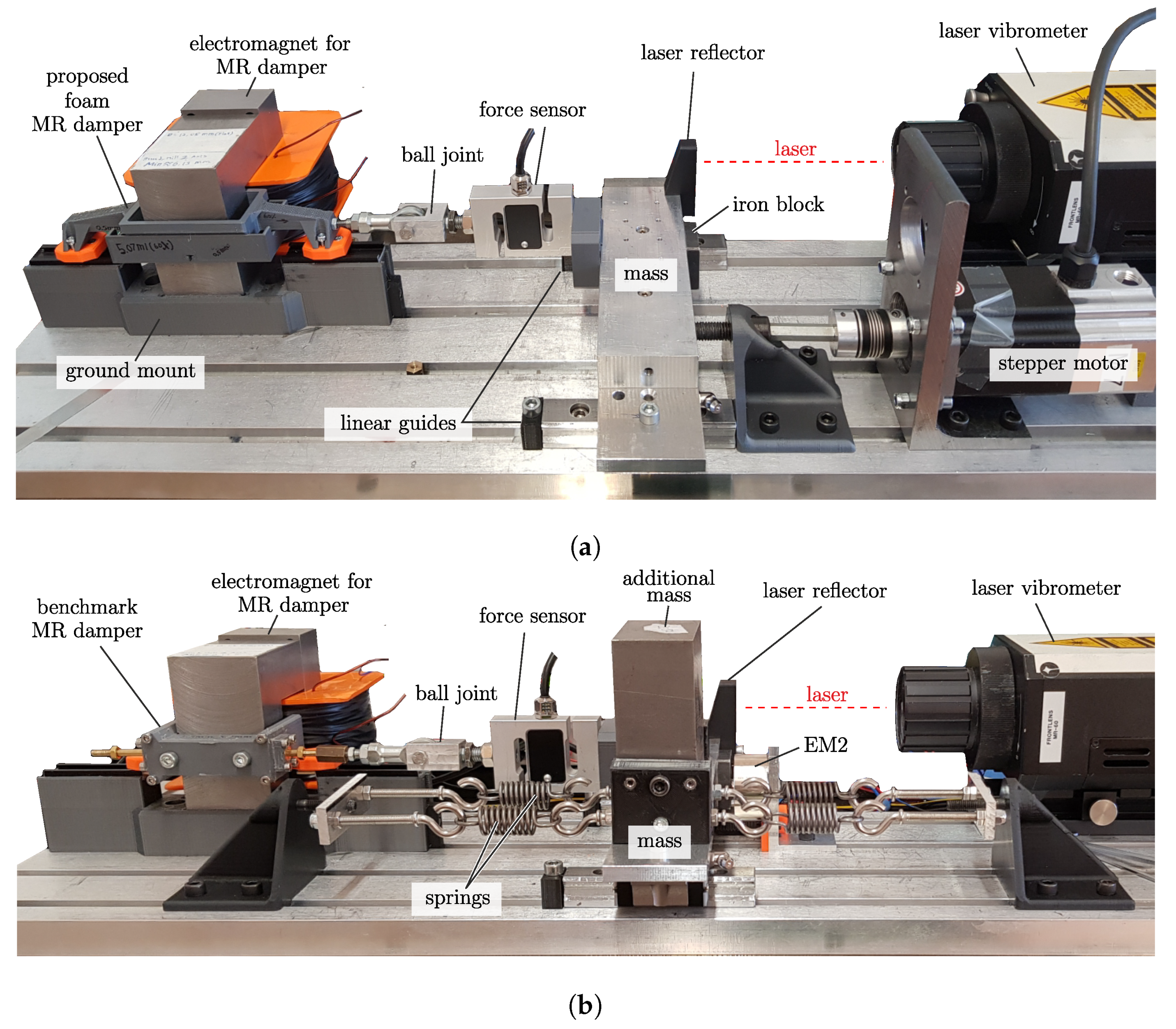
In this section, the results from the experiments will be presented. As mentioned before, there are two configurations of the experimental setup used for different investigation purposes (see
Figure 10). The first results describe the characteristic of each MR damper. The experiment is conducted using the experiment configuration, shown in
Figure 10a. The second part is the result from the experiment in a vibratory system. The experiment is conducted using the experiment configuration, shown in
Figure 10b. The results of both configurations will be explained and discussed in this section to show the performance of both MR dampers.
4.1. Benchmark MR Damper
First, the measurement results displaying the characteristic of the benchmark MR damper are presented. In the experiments, the stepper motor is used to actuate the movement of the damper. The movement including the velocity of the damper will be measured by the vibrometer; meanwhile, the resulting force is measured by the attached force sensor. The generated movement is controlled so that the same movement can be repeated in the experiments. The measured forces are then plotted to their respective velocities. The measurement results including the comparison to the mathematical model are presented in
Figure 11.
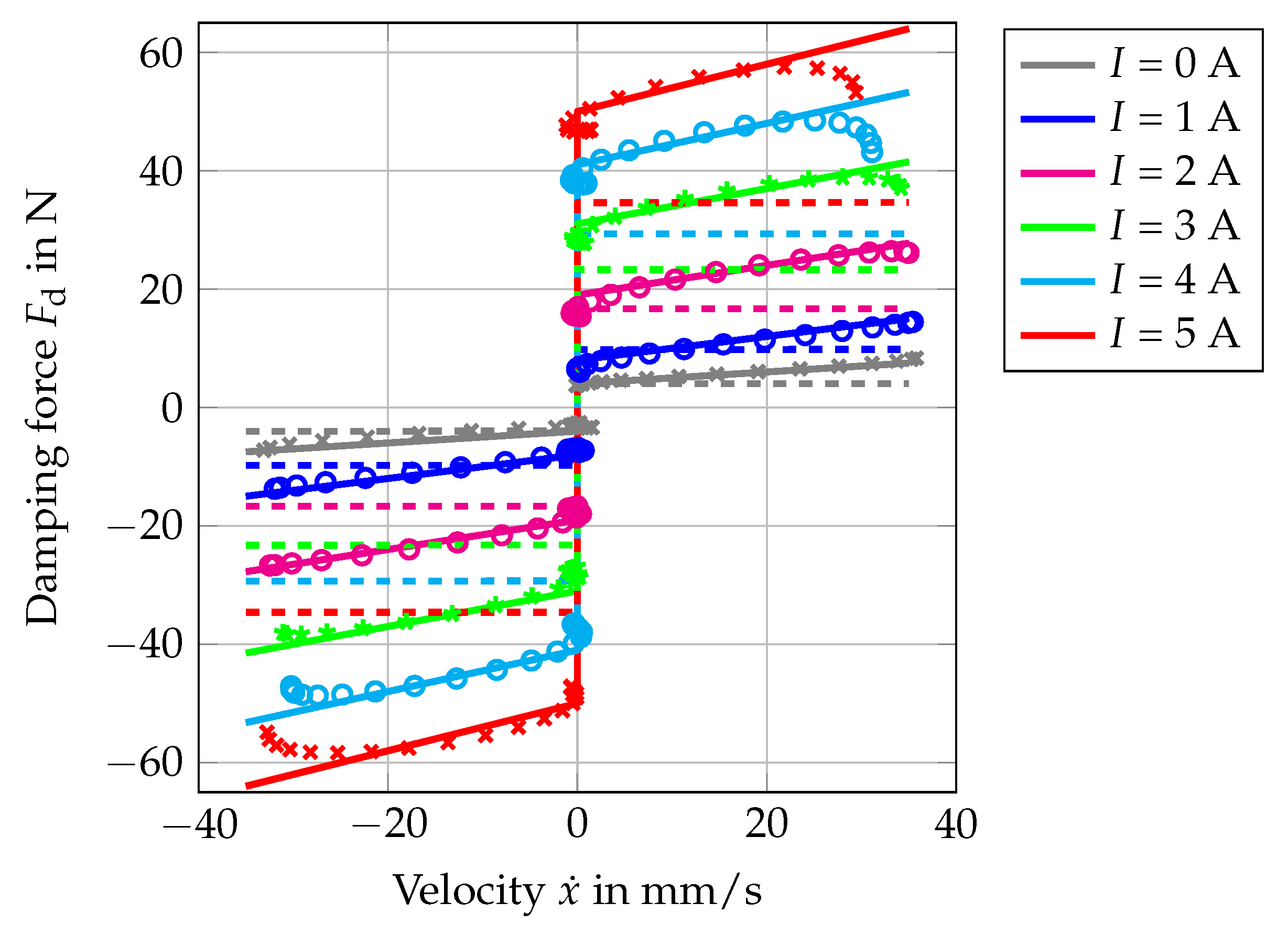
There are three group plots presented in
Figure 11. The first one is the measurement results, which are plotted using the marks. The second one is the ideal mathematical model, which is plotted using dashed lines. The third one is the modified mathematical model, which is plotted using continuous solid lines. The same color is used for the plots with the same amount of applied current
I. The ideal mathematical model is derived from Equation (
7):
with
being the friction constant for the friction due to the sealing, and
d and
are the theoretical damping constant and blocking force, respectively, whose values can be calculated using Equation (
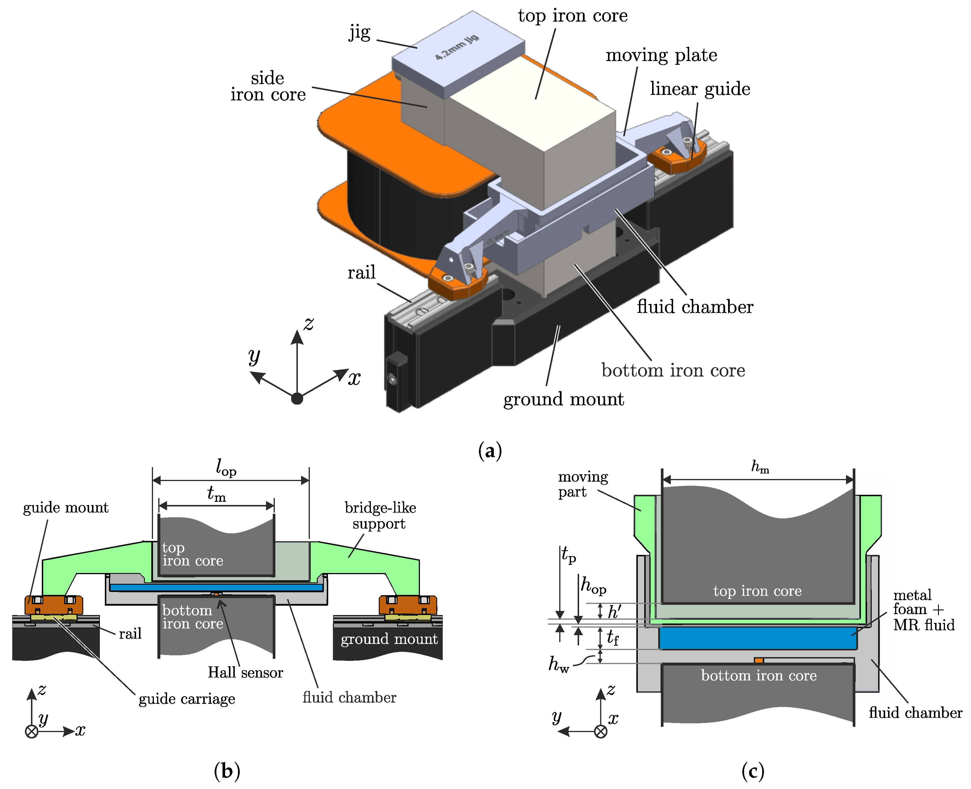
6). The theoretical damping constant should not vary since the operating area
, operating gap distance
and the viscosity
are constant parameters, as listed in
Table A3. The theoretical blocking force
varies, dependent on the magnetic field density yield stress
at the load section. The magnetic field is inserted in Equation (
2) to obtain the yield stress
and therefore the blocking force by multiplying it with the operating area
. The magnetic field density
B is the one measured by the integrated Hall sensor (see
Figure 9c), whose measurement results are listed in
Table 2.
The modified mathematical model
is an extension of Equation (
36), where the damping constant
has a dependency on the applied current. For both mathematical models, the damper parameters are written as a function of applied current
I instead of the magnetic field density
B. This is done to give a proper comparison between the benchmark MR damper and the proposed foam MR dampers, since those dampers will have different operating magnetic field densities due to their different configurations.
As can be seen in
Figure 11, the measurement results and the results from the ideal mathematical model (
36) with calculated parameters do not fit together. For the condition when no magnetic field is applied (
), there exists no blocking force (
). Therefore, the existing offset is the friction force
from the sealing. As the velocity exists (
), the measurement results show bigger forces
than the one calculated from the ideal mathematical model. This shows that the damper has a higher damping constant
d. When the magnetic field is applied (
), the blocking force
is increasing as the current increases. It is, however, to be observed that as the current is applied, not only the damping constant
d but also the blocking force
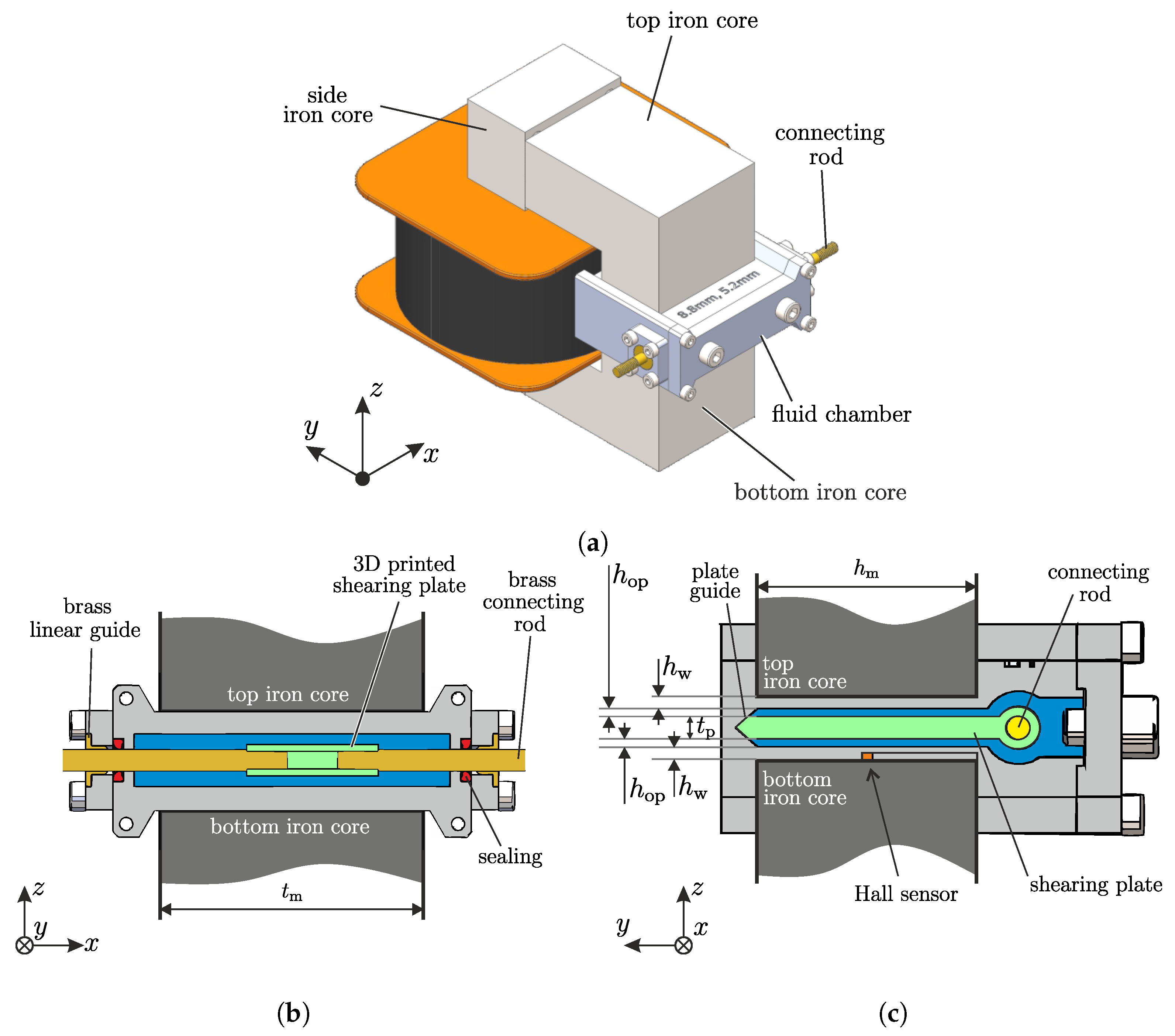
from the measurement has higher values than the one calculated from the ideal mathematical model. The difference is suspected to be caused by the operating mode of the damper itself. First, even though the damper is planned to be operated in the shear mode, the damper structure is not exactly the one used in conventional shear mode. The shearing plate is not covering the whole operating area (
Figure 3a), but it is shorter than the operating area of the magnetic field
Figure 4b. Therefore, during its movement, the shearing plate not only shears the fluid between the plate and the housing but needs to oppose the solidified MRF along its path. Second, the side of the shearing plate has a flat surface, which causes an additional drag force when it is moving through the fluid. Since the damper is used only as a benchmark, the influences from those two effects on the measured results are not investigated further. Because of the discrepancies between the ideal mathematical model and the measurement results caused by the mentioned reasons, the benchmark MR damper characteristic is described using the modified mathematical model (
37). For this mathematical model, the dampers parameters are fitted to the measurement results and the fitted parameters (
d and
) are listed in
Table 2. The parameters are fitted using the least mean square method, where the fitted lines should deliver the least difference to each respective set of experimental result. As can be seen in
Figure 11, the modified mathematical model and the measurement results are in good agreement.
There are three things that need to be highlighted from the investigation. First, this benchmark MR damper was designed to operate using shear mode and have a comparable operating size to the proposed foam MR damper. As can be seen in the
Table A2 and
Table A3, this benchmark MR damper has an equal operating area with the proposed foam MR damper (
= 1500 mm
) and similar operating gap
. Therefore, the two MR dampers can be assumed to be comparable. Second, the shear operating mode is chosen for the benchmark MR damper to achieve the lowest parasitic force due to sealing possible. Since the sealing should not withstand any pressure in the fluid chamber, the sealing may have low friction constant, and therefore, the parasitic damping due to the sealing friction can be minimized. The smallest friction force achieved using this setup is measured to be 4 N (see
Table 2). Third, some unknown effects caused the error between the mathematical model and the measurement results. It is also to be observed, that for higher applied current (
A), the force shows a
shear thinning characteristic, which causes an increasing discrepancy between the mathematical model and the measurement results as the velocity is increased. However, these differences are not further investigated, since this MR damper is not the main focus of the work and will only be used as a benchmark in this work to give an estimation of how big the operating force can be generated for the chosen damper geometry. Therefore, the fitting of the model parameters is assumed to be sufficient to describe the characteristic of this benchmark MR damper.
4.2. Foam MR Damper
In this work, some damper parameters are varied in order to find the best design approach for the damper. For this purpose, the MR fluid filling ratio
and the operating gap
of the proposed MR damper are varied. The MR fluid filling ratio
is defined to be the volume ratio of the MR fluid
to the volume of the nickel foam
(listed in
Table A2). In this work, the tested MR filling ratio
will be 60%, 75%, and 90%. The filling ratio of 100% was not tested because the same volume of the MR fluid will not fit in the metal foam to be contained. The second varied mechanical parameter is the operating gap
. The investigation is conducted to find the limiting air gap of the foam MR damper, which is defined by the gap in which the MR effect is still applicable. On one hand, if the gap is too small, there will be a possibility that the carrier fluid of the MR fluid will stay in contact with the shearing plate, even though no magnetic field is applied. This could happen especially for the 90% MR filling ratio due to the wetting effect of the fluid on the foam surface. This will increase the parasitic damping force due to the viscous effect, whose effect should be eliminated by the proposed structure. On the other hand, when the gap is too large, the MR fluid particles will not reach the shearing plate in its ON state. In this work, the investigated operating gaps are 0.5 mm, 1.0 mm, and 1.5 mm.
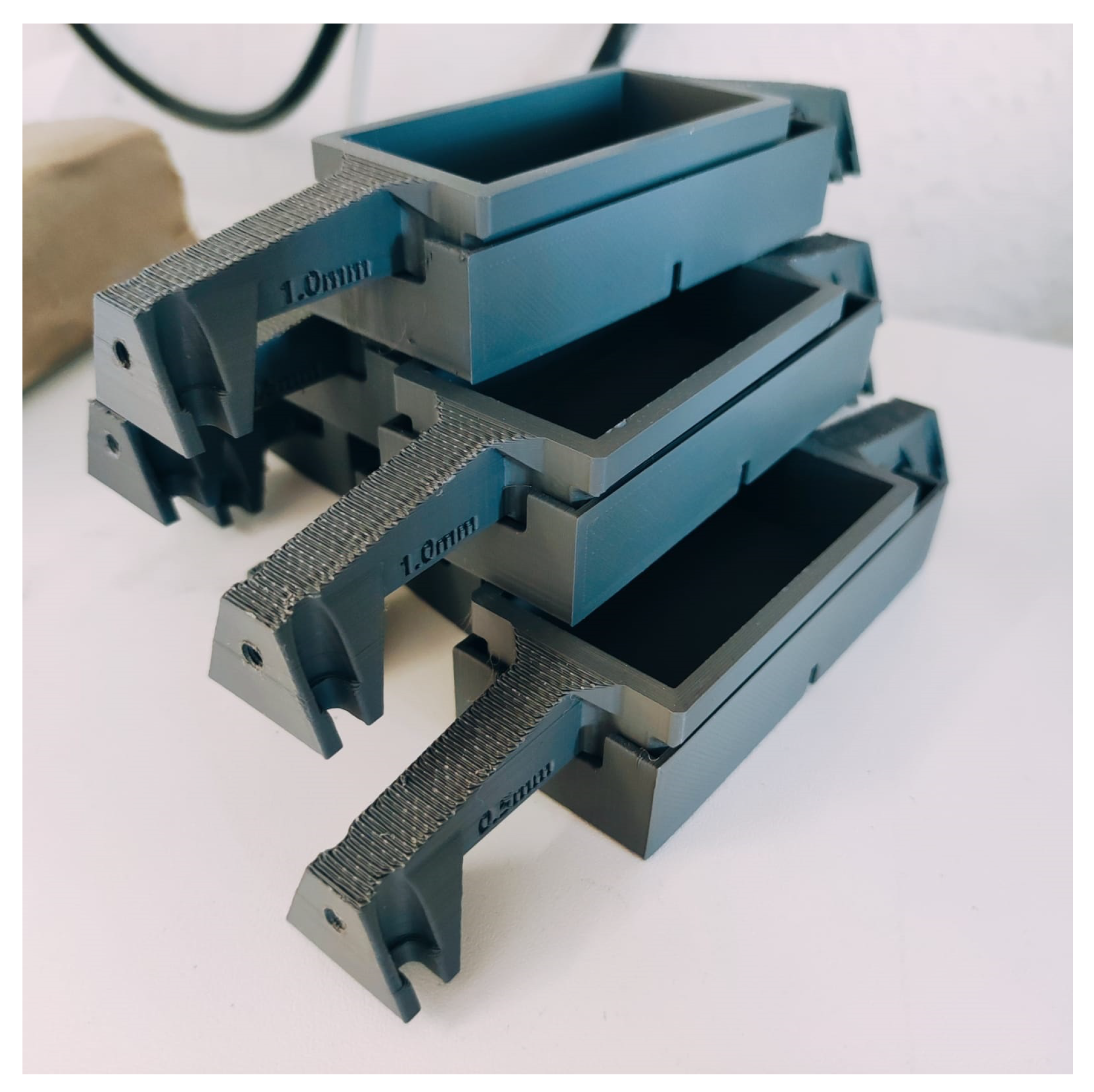
To perform this investigation, both the fluid chamber and the shearing plate are made multiple.
Figure 12 depicts the multiple chamber-plate set, each for one investigated parameter set. Since both the chamber and the plate are 3D-printed, they can be manufactured equally despite having a complex structure. The measurement results to describe the characteristic of the proposed foam MR-dampers are presented in
Figure 13.
The measurement procedures are identical to the one conducted for the benchmark MR damper. It can be seen from the results that even though there is no contact between the shearing plate and the MR fluid in its OFF state, there still exists an offset in the force. This is caused by mechanical contact from the guides in the system. Moreover, it is to be expected that more MR particles are drawn out from the metal foam as the current increases. This might vary the damping constant
d of the damper as well. Therefore, Equation (
37) will be the suitable model for describing the damper characteristic. It is to be noted that no mathematical model describing the MR damper with foam structure has been proposed in the previous work [
16,
17,
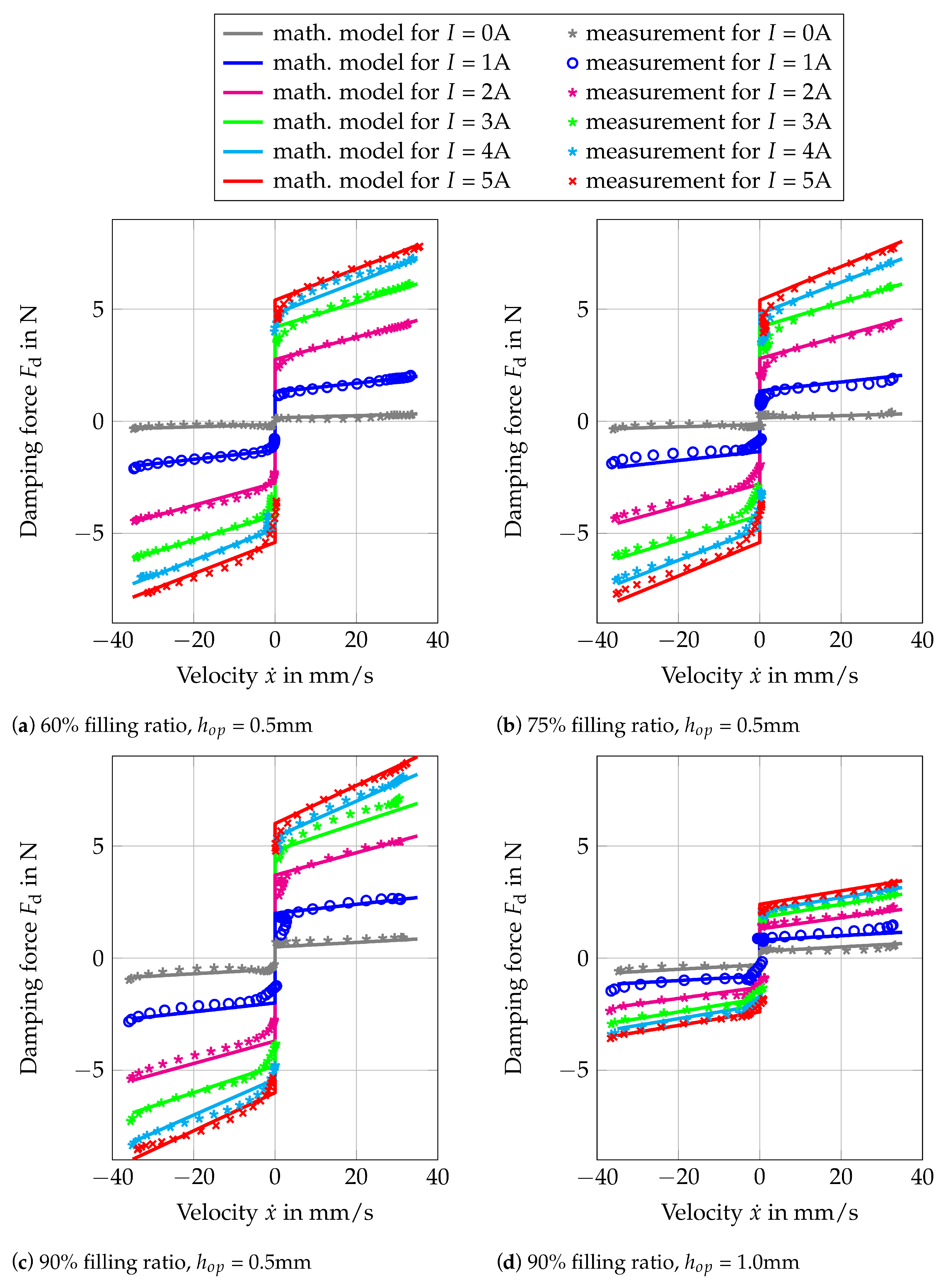
18]. In the same manner, as in the previous result presentation, the measurement results and the mathematical model are plotted using the marks and the continuous lines, respectively. The same color represents the same excitation current during the measurement. The mathematical model is the one from Equation (
36), whose parameters are obtained by fitting them to the measurement results. All the fitted parameters are listed in
Table 2. As can be seen in all four plots, the measurement and the mathematical model are in good agreement.
Figure 13a–c present the results for the investigated foam MR damper with operating gap
of 0.5 mm, with MR filling ratio
of 60%, 75%, and 90% respectively. As can be seen from those three figures, the resulting force is approximately 10× smaller in comparison to the benchmark MR damper. This is despite the fact of having the same shear operating area and similar magnetic flux density for various applied currents (see
Table 2). This is due to the reason that using this foam configuration in the MR damper, there will be fewer MR particles in the ON state, that have contact with the shearing plate during its operation. Therefore, the resulting force will be smaller as well. It can also be observed from these results that for an operating gap of 0.5 mm, the MR filling ratio has almost no influence on the force-velocity characteristic of the damper. A small increment of both damping constant and blocking force for various applied currents can be seen in
Table 2 as the MR filling ratio is increased. Thus, the increment is considered to be insignificant. Another point to be observed is the parasitic damping due to the friction from the guides. Since there is no sealing mechanism required, the guides are the only friction source in the system. As listed in
Table 2, the friction from the guides is small. For the three MR filling ratios, a friction constant of less than 0.5 N can be achieved. This is a big improvement in comparison to the sealing friction in the benchmark MR damper, which is 4 N. The other parasitic damping, which is caused by the viscous effect of the fluid in its OFF state is 10–20× smaller in comparison to the benchmark MR damper. This is due to the reason that the MR damper is designed to have no contact with both the metal foam and the MR fluid. However, by the MR filling ratio of 90%, it can be observed that there is an increment of the damping constant during its OFF state. This is suspected to be caused by the wetting effect of the fluid, which can not be absorbed fully by the metal foam.
Combining the combination of the investigated MR filling ratio and the operating gap, there are nine foam MR dampers in total to be investigated. Nevertheless, as can be seen in
Figure 13, only the results of four representative foam MR dampers are presented. When the operating gap is increased to 1.0 mm, the parasitic damping effect due to the viscous effect (due to the wetting of the fluid) is decreased. However, the controllable blocking force due to the magnetorheological effect is drastically reduced as the consequence. This is shown in
Figure 13d, where the total force is approximately reduced by half. It is obvious from the four presented results, that either a bigger operating gap (
mm) or less MR filling ratio will result in an even smaller force. This is the reason that the results of the foam MR damper with an operating gap of 1.5 mm and the foam MR damper with an operating gap of 1.0 mm with less MR filling ratio are not presented.
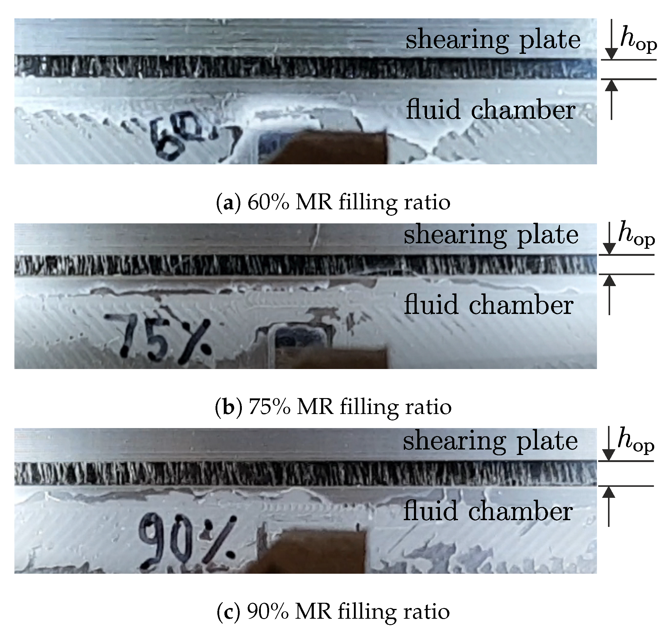
Despite having a small resulting force, the foam MR damper with 1.5 mm can be used to visualize the ON state of the proposed foam MR damper. By replacing one chamber wall with plexiglass and using a daily camera from a smartphone, the structure of the drawn-out MR particles can be seen.
Figure 14 shows the picture of the ON state for different MR filling ratios with an operating gap of 1.5 mm.
The figures show how the MR particles are being drawn out from the foam when the magnetic field is applied. The particles built pillar-like structures between the shearing plate and the fluid chamber, parallel to the magnetic field direction. It is also to be observed, that more particles can be seen at a higher MR filling ratio.
4.3. MR Damper in Vibratory System
After investigating the characteristic of each MR damper, the MR dampers are tested in a vibratory system. The experiment is conducted using the experiment configuration, shown in
Figure 10b. Based on the results obtained in the previous section, both the MR dampers have varying damping constant as the applied current varies. Moreover, there is additional friction from the linear guide of the vibrating mass itself. Therefore, the mechanical representation in
Figure 6b does not represent the working principle of both MR dampers in the vibratory system.
Figure 15 depicts the correct representation of the vibratory system, adapting the air damping
and additional friction
from the guides of the vibrating mass.
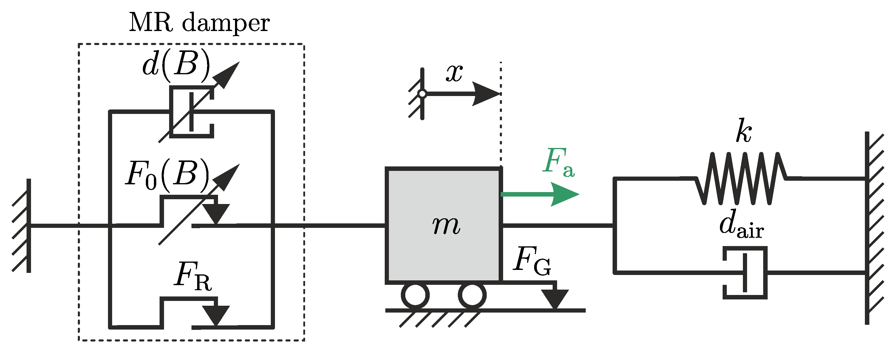
The vibratory system consists of a mass
m and springs, with a total stiffness of
k. The mass is guided to allow the resulting vibration to occur only along one axis. The friction from the guides of the vibrating mass has friction with friction constant of
. Together with the springs, the MR damper will be attached to the mass, so that the damper and the spring have a parallel arrangement. The MR damper is represented as a parallel arrangement of a viscous damper element with a varying (symbolized by the diagonal arrow) damping constant
, a friction element with varying friction constant
, and a friction element with fixed friction constant
. This represents the damper mathematical model in Equation (
37). Using this configuration, the whole vibratory system possesses the following differential equation:
where all the damping and friction constant can be added together. The parameter of the proposed foam- and benchmark MR dampers have been identified in
Section 4.1 and
Section 4.2 give the value of the friction force
due to the sealing or guide of the damper, viscous damping constant,
and the blocking force
for different applied current conditions. The obtained parameters can be found in the
Table 2. For the complete vibratory system, the other two parameters, namely, the friction constant
from the guides of the moving mass and the damping constant
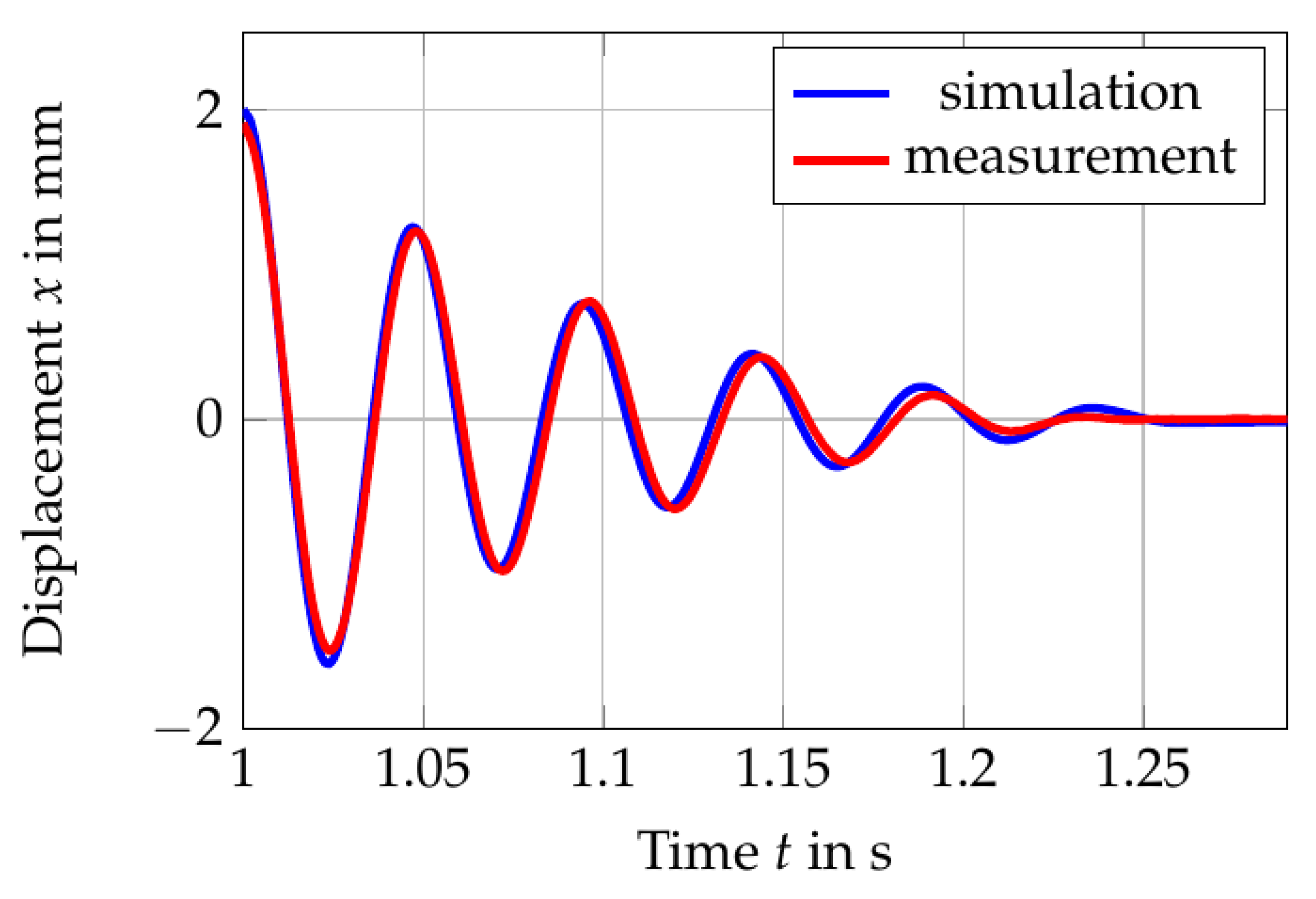
from air need to be identified. This is done by fitting those parameters to the free vibration response of the vibrating mass when there is no damper is attached.
Figure 16 depicts the comparison of the measured and simulated response, where SIMULINK from MATLAB2019b is used to solve the equations for non-linear system numerically.
The results in the figure are assumed to be in good agreement, with
N and
Ns/m. The fitted values of the friction constant
and the damping constant
are used to simulate the vibratory system with the configuration shown in
Figure 15.
4.3.1. Free Vibration Behavior
In this part of the investigation, the electromagnet EM2 is placed at a specified distance to the initial position of the mass. The mass is then pulled and the EM2 is activated, holding the mass using the magnetic force. The electromagnet of the MR damper is activated and the state of the MR fluid in the chamber is initialized. After the initialization process is done, the EM2 is deactivated. The mass vibrates freely due to the stiffness of the springs. The vibration of the mass is measured by the vibrometer. Based on the measurement results, the damping from the damper is then examined. The measurement results are presented in
Figure 17 and
Figure 18.
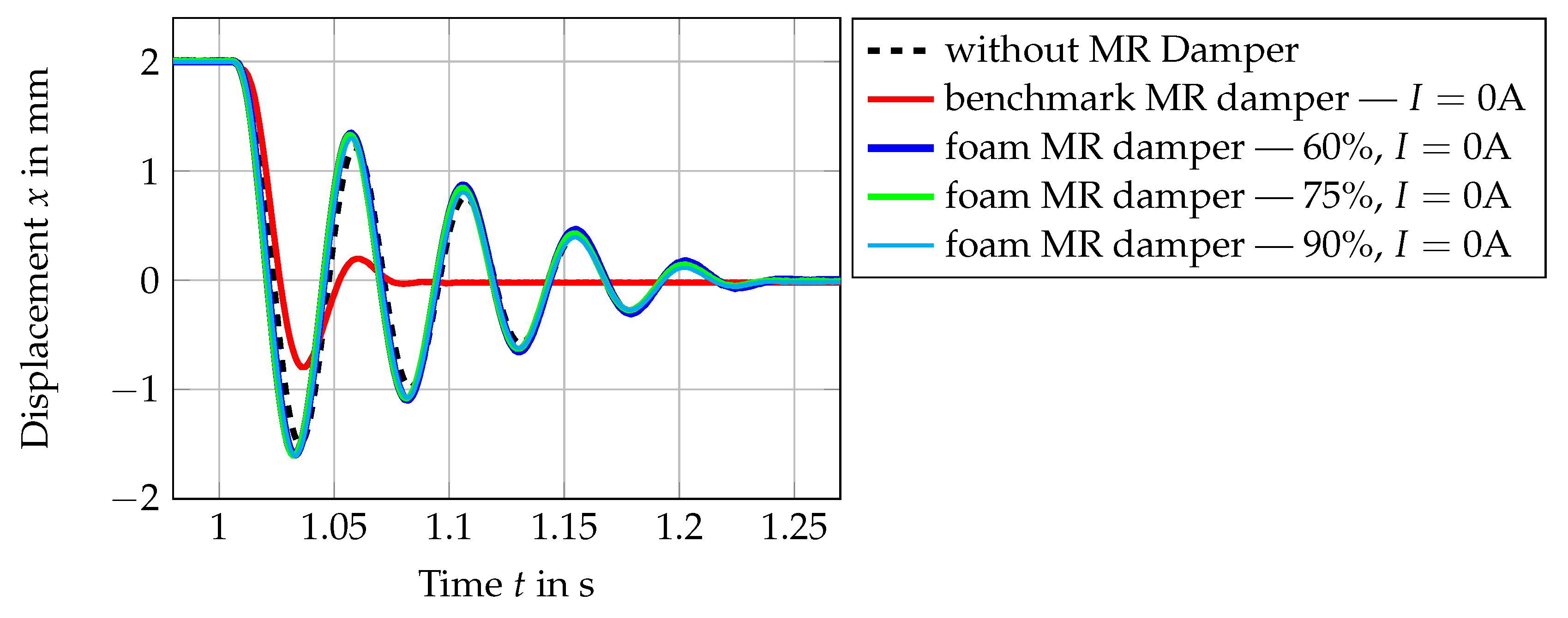
The results in
Figure 17 show the comparison of the free vibration of the mass with and without the MR damper. As is shown in this figure, when there is no MR damper attached, the vibration decays after approximately 260 ms (after 5 periods of vibration), starting from the time when electromagnet B is deactivated. The damping in this state comes from the air and friction from the guides. As soon as the benchmark damper is attached, the decay time of the vibration reduced significantly to about 85ms, even without applying any current at the coil. This shows that the passive damping from the benchmark MR damper has added considerable damping in the system. In comparison to this, when the proposed foam MR damper is connected to the vibratory system, the decay time stays almost unchanged (about 260 ms). It can be concluded from this experiment that the proposed MR damper has a small amount of parasitic damping. In contrary, by only integrating the benchmark MR damper in the system, the damping has been increased by a significant amount.
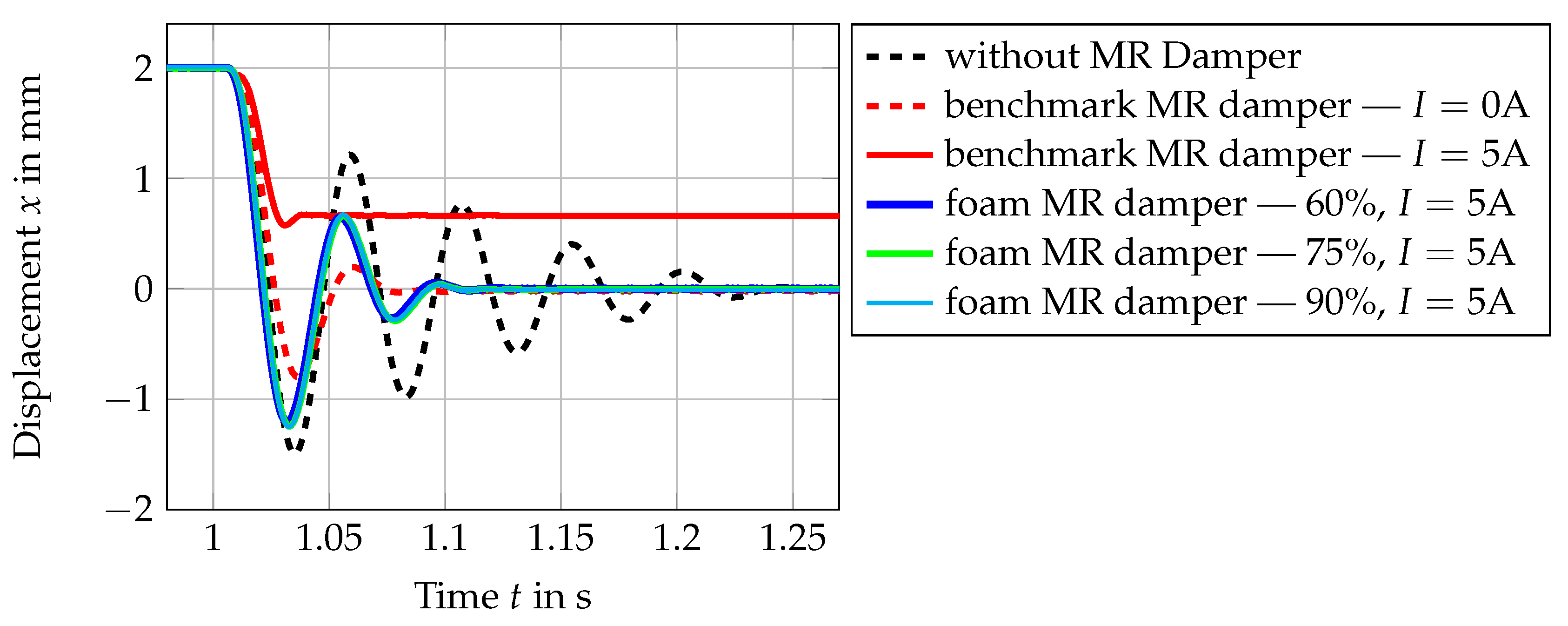
The results in
Figure 18 show the results when both the benchmark damper and the foam damper are activated with an applied current of 5 A.
As can be seen in this figure, for the ON state of the foam MR damper with 5 A, the damping in the system is increased and therefore, the settling time of the free vibration is reduced from 260 ms to 110 ms. The settling time of the mass with the foam MR damper with 5 A applied current is almost the same settling time achieved by inserting the benchmark MR damper in the vibratory system without activating it. For the case when 5 A is applied for the benchmark MR damper, the settling time is further reduced to 40 ms. It is also to be observed for this case that since the yield force of the benchmark MR damper with 5A is high, the vibrating mass has another settling position.
4.3.2. Equivalent Damping Ratio
The results in
Figure 17 and
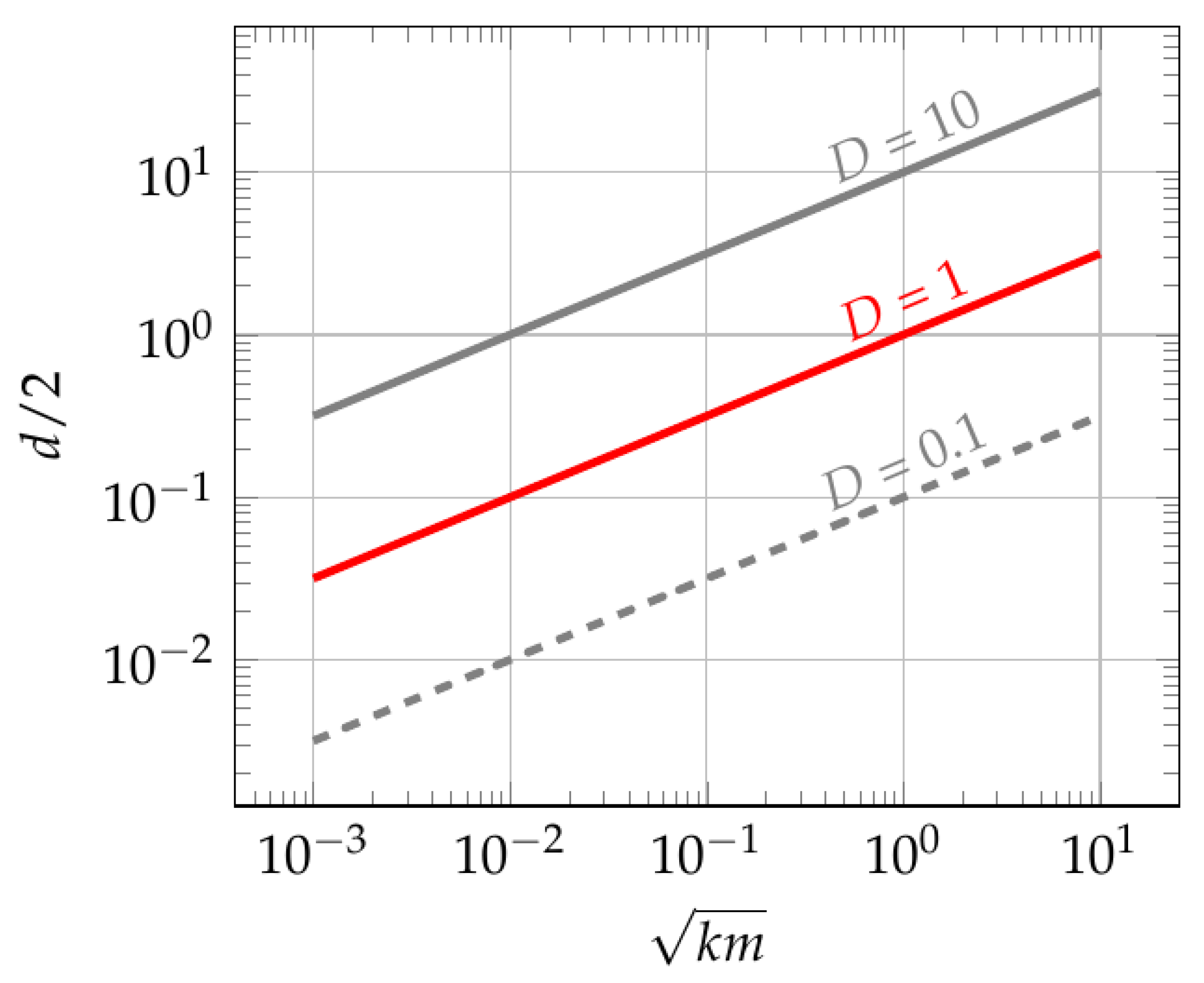
Figure 18 verify the influence of the parasitic damping force in a vibratory system. By having a high parasitic damping in the system, a significant amount of damping is added with it to the system. This results in a reduction of the system dynamic. In order to quantify the damping in the vibratory system, the method in
Section 2.5.3 is used. This method allow an estimation of the damping ratio
D of the system based on the peak of the amplitude response of the vibratory system. In this way, an equivalent damping ratio can be obtained despite the system being nonlinear.
In order to obtain the equivalent damping ratio, a simulation using the identified parameters of both dampers and the vibratory system is conducted. The damper identifications in
Section 4.1 and
Section 4.2 give the value of the friction force
due to the sealing or guide of the damper, viscous damping constant,
and the blocking force
for different applied current conditions. The obtained parameters can be found in the
Table 2. The other two parameters, namely, the friction constant
from the guides of the moving mass and the damping constant
from air were identified in
Section 4.3 and listed in
Table A4. The simulation is conducted using SIMULINK 10.0 from MATLAB2019b. All the known parameters are inserted in the simulation and a chirp signal
is used as the input, with
k as the vibratory system stiffness and
as the rate of change of the frequency over time.
c is chosen so that the chirp rate is slow enough to build the figure.
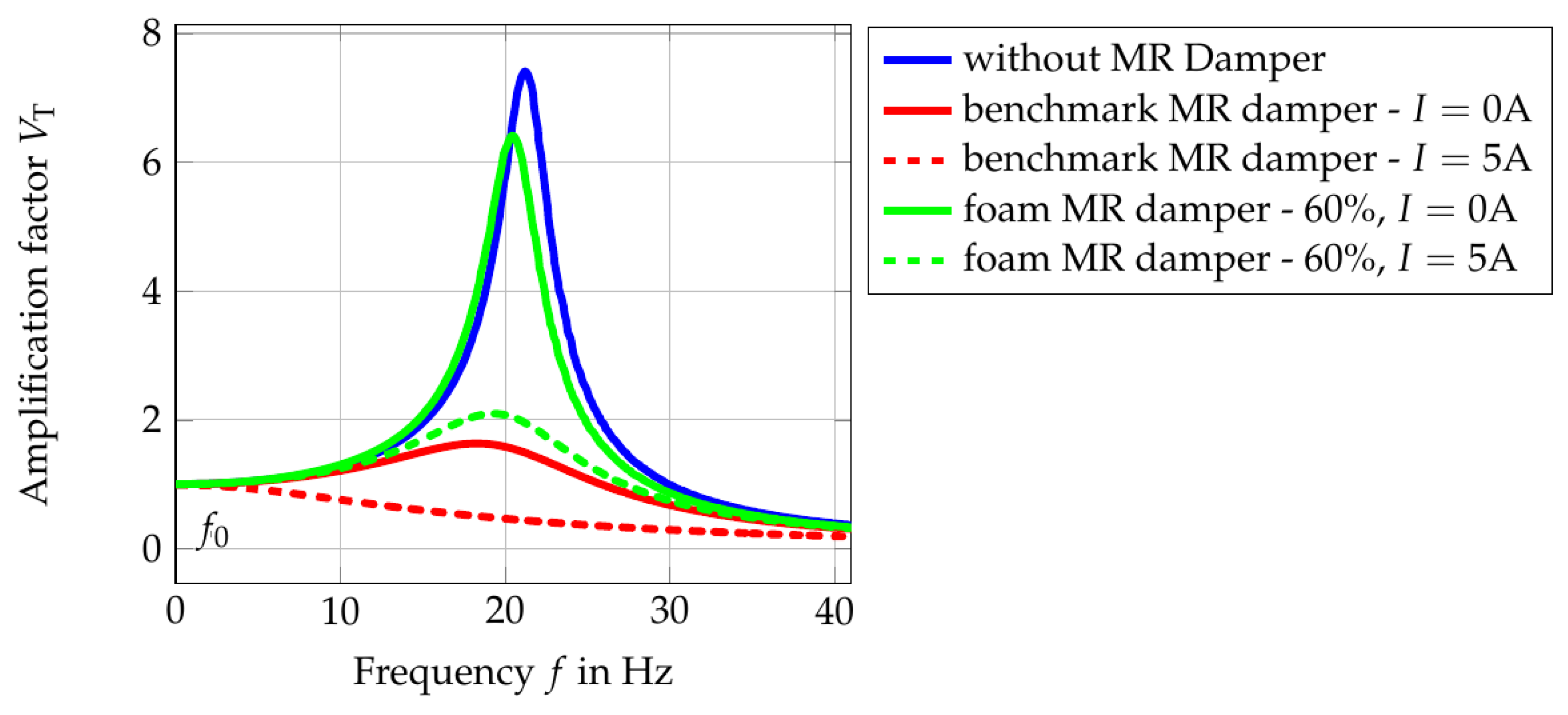
Figure 19 shows the amplitude response of the vibratory system for different damper conditions.
In this figure, the peaks of the system response are enveloped and plotted over the frequency. The investigation is conducted up to the frequency twice the natural frequency of the vibratory system. The maximum point of each amplitude response is taken as the quality factor
Q. By inserting the peak value
Q in Equation (
24), the damping ratio
D can be estimated. The calculated equivalent damping ratio is listed in
Table 3.
The results show that the utilization of the benchmark MR damper in the vibratory system increased the default damping ratio
D from 0.067 to 0.323 just by attaching it to the vibratory system. By increasing the applied current to the maximal amount of 5 A, the vibratory system possesses an equivalent damping ratio that might be bigger than 0.707 (see
Section 2.5.3). That means that by using the benchmark MR damper, the damping of the system can be operated with a damping ratio range from 0.323 to a damping ratio that could be bigger than 0.707. In small-scale applications, the damping ratio of 0.323 is considered to be big. As can be seen in
Figure 17, the system response becomes slower just by attaching it to the system. In comparison to that, the utilization of the foam MR damper changed the default damping ratio
D from 0.067 to 0.078. It can be said that the dynamic of the system is almost unchanged. However, due to less interaction between activated MR particles and the shear surface, the generated damping force is also less in comparison to the benchmark MR damper. With an applied current of 5 A, the equivalent damping ratio of the system becomes 0.246, which is still smaller than the damping ratio of the benchmark MR damper in its OFF state. Nevertheless, as explained in the design procedure, the upper limit of the proposed MR damper can be increased easily without changing the dynamic of the system.


