Article

Thermoplastic Polyurethane/Lead Zirconate Titanate/Carbon Nanotube Composites with Very High Dielectric Permittivity and Low Dielectric Loss

1
Advanced Composites Laboratory, School of Mechanical and Materials Engineering, Washington State University, 2710 Crimson Way, Richland, WA 99354, USA
2
Department of Plastics Engineering, University of Massachusetts Lowell, 1 University Ave, Lowell, MA 01854, USA
*
Author to whom correspondence should be addressed.
J. Compos. Sci. 2020, 4(3), 137; https://0-doi-org.brum.beds.ac.uk/10.3390/jcs4030137
Submission received: 3 September 2020 / Revised: 16 September 2020 / Accepted: 16 September 2020 / Published: 17 September 2020
(This article belongs to the Special Issue Feature Papers in Journal of Composites Science in 2020)

Abstract

:
Ternary composites of flexible thermoplastic polyurethane (TPU), lead zirconate titanate (PZT), and multiwalled carbon nanotubes (MWCNTs) with very high dielectric permittivity (εr) and low dielectric loss (tan δ) are reported. To assess the evolution of dielectric properties with the interactions between conductive and dielectric fillers, composites were designed with a range of content for PZT (0–30 vol%) and MWCNT (0–1 vol%). The microstructure was composed of PZT-rich and segregated MWCNT-rich regions, which could effectively prevent the formation of macroscopic MWCNT conductive networks and thus reduce the high ohmic loss. Therefore, εr increased by a maximum of tenfold, reaching up to 166 by the addition of up to 1 vol% MWCNT to TPU/PZT. More importantly, tan δ remained relatively unchanged at 0.06–0.08, a similar range to that of pure TPU. εr/tan δ ratio reached 2870 at TPU/30 vol% PZT/0.5 vol% MWCNT, exceeding most of the reported values. This work demonstrates the potential of three-phase polymer/conductive filler/dielectric filler composites for efficient charge storage applications.

Graphical Abstract

1. Introduction

With the continuous demand for enhanced materials in diverse areas of applications, research has progressed toward multi-phase materials with complementary properties, which are not obtainable using the constituents individually. Polymers provide good specific mechanical properties, chemical stability, and processing possibilities, but exhibit very low electrical conductivity and poor dielectric permittivity. Therefore, research on high-performance polymer-based dielectric composites with high permittivity has demanded considerable attention [1,2,3,4,5].
The rapid development of the electronic industry and minimization of electronic devices has brought about a demand for more compact and powerful capacitors. Dielectric materials with high dielectric permittivity are widely required for applications such as energy storage in batteries and supercapacitors [6,7,8,9], actuators [10,11,12,13,14], electromagnetic interface (EMI) shielding [4,15,16,17], and static charge dissipation [18,19]. Ceramics such as barium titanate (εr = 1700 [20]) and lead zirconate titanate (εr = 3400 [21]) exhibit very high relative permittivity, but they are brittle and heavy with low dielectric strength [22] and difficult fabrication processes. On the other hand, polymers are light, ductile, and easy to shape with high dielectric strengths [23], but possess very low relative permittivity (εr < 4 for most of polymers). Therefore, ceramic-polymer composites form a potential material group for dielectric functional materials, having high permittivity and improved breakdown strength, while retaining low dielectric loss of the polymer matrix [1,22]. However, because of the very low dielectric permittivity of polymers, in order to achieve functional levels of permittivity, the composite requires dielectric ceramic filler, usually greater than 50 vol% [24,25,26,27,28,29]. This, in turn, results in a composite with poor mechanical properties, poor processability, and poor adhesive strength.
A few strategies have been developed to address the shortcomings of polymer-ceramic composites. One of the most widely studied methods has been to utilize electrically conductive filler/polymer composites (CPCs) [5,30,31,32,33,34,35,36]. In CPCs, according to the percolation theory, a high permittivity can be obtained as the conductive filler content approaches the percolation threshold [5]. This rise in permittivity is however accompanied by a very large jump in dielectric loss, due to the formation of conductive networks [35,37]. Once the direct connection is established between the conductive fillers, the ohmic loss increases greatly, thereby increasing the dielectric loss of the composite and making the CPC not suitable for charge storage application. Due to this narrow range of insulator-conductor transition, it is difficult to design CPCs with high permittivity and low loss. In order to prevent the direct connection between the conductive fillers, several methods have been examined [1,35,37,38,39,40,41]. One approach is to form three-phase composites by incorporating a non-conductive filler to the system, which will obstruct contact and, therefore, sustain charge storage ability [25,26,28,41].
A similar three-phase strategy may also be proven effective in enhancing the performance of ceramic-polymer composites. In this method, to enhance the dielectric permittivity or decrease the required ceramic loading, a highly conductive third phase (filler) is introduced to the system to impart partial percolation [25,26,27,28,37,39,41,42,43,44]. The role of the conductive filler is to promote the transfer of charge carrier between the other two phases, i.e., polymer matrix and ceramic filler [45]. Study of this method has been limited and its potential needs to be further examined. Carponcin et al. [42] have investigated the properties of polyamide/PZT/MWCNT composites. For a 30 vol% ceramic filler content, the establishment of electrical connectivity of the MWCNTs was studied, but the results showed no huge enhancements in the dielectric properties [42]. The dielectric loss of the samples was also not reported, which prevents the reader from concluding the suitability of the work for charge storage applications. Some other researchers have investigated PZT/CNT composites with various matrices. Overall, the resultant composites have either very high dissipation factor [25,27] or low dielectric permittivity [26,44].
Three-phased dielectric composites can be produced with industrially established polymer processing methods such as injection molding and compression molding. This brings an array of diverse properties [46] and significant processing advantages compared to some of the complicated processing methods proposed for the enhancement of dielectric performance, e.g., fabrication of core-(single/double) shell structures [29,35,47]. Arjmand et al. [33] studied the effect of filler alignment to obstruct the direct contact of MWCNTs in MWCNT/polystyrene (PS) composites. The composites were made by injection molding process and showed promising results. Ameli et al. [5,32] investigated the effect of foaming and adding air as the third phase to polypropylene/MWCNT composites and achieved good dielectric performances using simple processing methods.
A variety of micro-sized conductive fillers has been used in polymer composites, including carbon fiber [48,49], stainless steel fibers [50,51], and metallic fillers [52]. However, the nano-sized dimension, high aspect ratio, very high electrical conductivity, and extraordinary mechanical properties of MWCNT have made it the most promising filler for CPCs. It is additionally noted that carbon nanotubes form a strong Van der Waals bond between one another and aggregate into quasi-spherical particles, which makes the production of the composite more difficult.
An important feature of emerging electronic devices is their combination of flexibility and conformability. This combination allows further minimization of circuitry size and provides new opportunities for applications for which following the basic shape of the equipment is important. However, most of the reported polymer composites for dielectric applications are based on rigid polymers (Table 1), which lack sufficient mechanical flexibility, especially at high filler loads. In this study, thermoplastic polyurethane (TPU) was selected as the polymer matrix, in order to provide potential for flexibility. TPU is a block copolymer, composed of soft segments (SS) and hard segments (HS). The HS acts as the tie points between the chains and ties the rubbery SS chains together, in the same way vulcanization would [53]. However, since these ties are through crystals (not chemical bonds), they can be repeatedly melted and processed. TPU has the desired flexibility of vulcanized rubber while having the processability of a thermoplastic material, which lends itself to a wide range of physical properties, including tunable flexibility and stretchability.
In this work, we investigate strategies to create flexible dielectric composites with high dielectric permittivity and low dielectric loss. Three-phase composites are designed, fabricated, and tested to systematically investigate the effects of conductive and ceramic fillers on dielectric performance. PZT was used as a model high-dielectric ceramic filler and its content was fixed at 0–5–10–20–30 vol% and MWCNT was employed as the conductive filler with 0–1 vol% content. Dispersion of MWCNTs is a challenging assignment, due to their high aspect ratio and strong van der Waals bonds [54]. Poor dispersion results in bundles of entangled MWCNT. The novelty of this work is to leverage such segregated structure [55,56] in the resultant composites, which is created by having MWCNT-rich and PZT-rich zones, acting as micro-capacitors. Electrical conductivity, relative permittivity, and loss tangent of the composites were measured and εr/tan δ ratio was compared, in order to evaluate the effects of both conductive and ceramic fillers on the charge storage performance. The morphology of the samples was also evaluated in order to understand the underlying mechanisms of resultant dielectric behavior.

2. Materials and Methods

2.1. Materials

Commercially-available TPU (Elastollan 1185A, BASF Ltd., Florham Park, NJ, USA) having a density of 1.12 g∙cm−3 and a glass transition temperature of −38 °C was used as the base resin. PZT powder, with an average particle size of 1 μm, was supplied by Hammond Lead Products, Pottstown, PA, USA. NC7000 multiwalled carbon nanotubes of 90% purity having an average diameter of 9.5 nm, an average length of 1.5 μm, and a volume resistivity of 10−4 Ω·cm were purchased from Nanocyl S.A., Sambreville, Belgium. Tetrahydrofuran (THF) was purchased from VWR, Radnor, PA, USA and silver epoxy was procured from MG Chemicals, Burlington, ON, Canada. All materials were used as received.

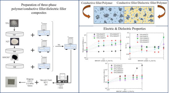
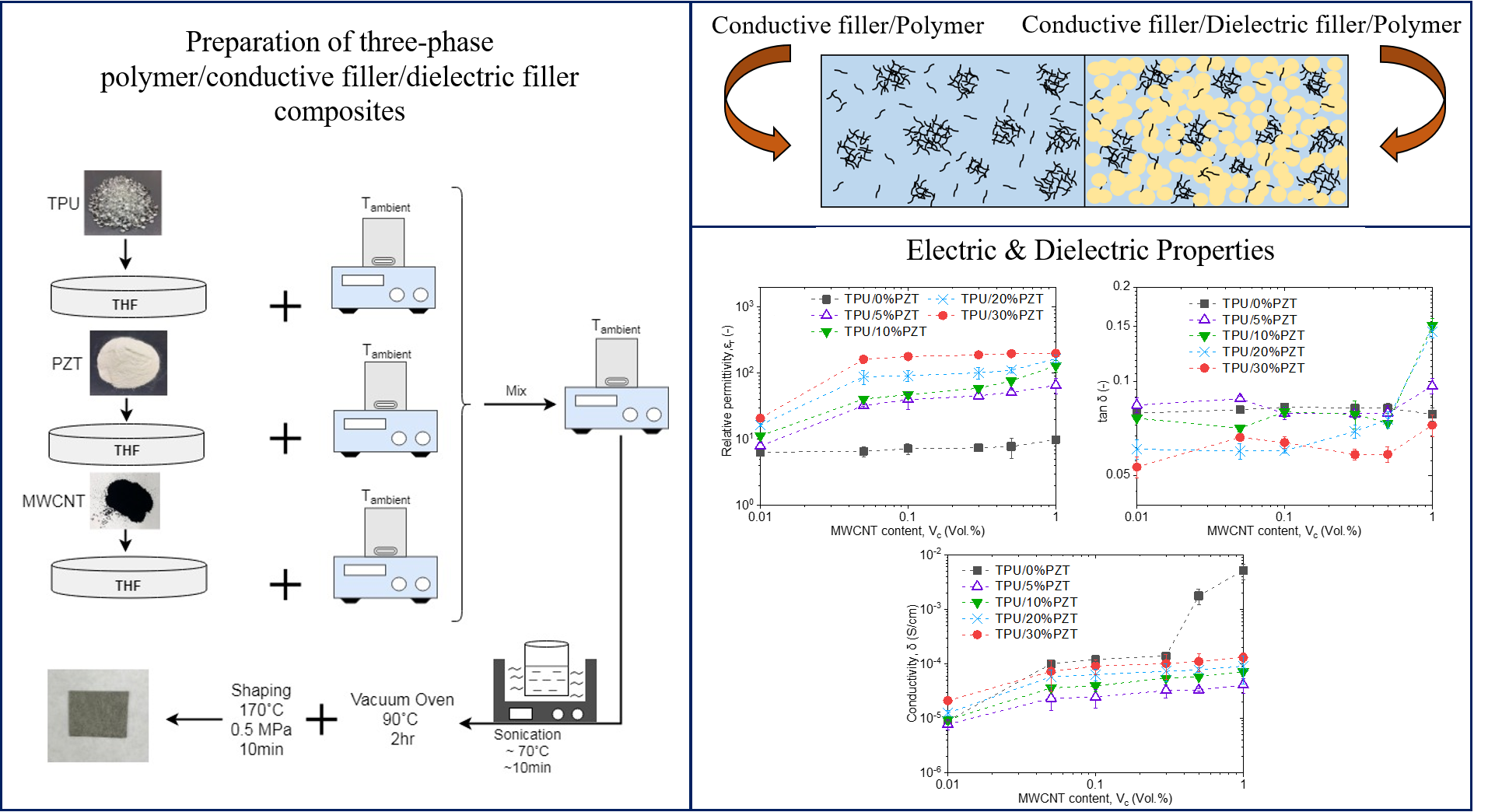
2.2. Sample Preparation

Various TPU-PZT-MWCNT composites, with PZT contents of 0–5–10–20–30 vol% and MWCNT contents of 0–0.05–0.1–0.3–0.5–1 vol% were fabricated via solution casting at room temperature. In this method, 5–10 g of TPU is dissolved in THF (with a ratio of 100 mL of THF per 5 g TPU) using a magnetic stirrer (Professional series, 7 × 7 Hotplate/Stirrer, VWR, Radnor, PA, USA) at ambient temperature. TPU pellets were oven-dried at 90 °C for 2 h to remove any excess moisture, prior to the casting. Proportionate amounts of PZT and MWCNT (each with a filler to THF ratio of 50 mL per 1 g of filler) were dispersed separately in THF, also with magnetic stirrers. Mixing the fillers separately provides the opportunity to control the dispersion level of each filler separately. As mentioned before, our target was a ‘segregated structure’ in which bundles of MWCNT are dispersed in a system of fully-dispersed PZT. After the full dissolution of TPU, the three aforementioned solutions were added and thoroughly mixed together, with a magnetic stirrer. The slurries were then placed into an ultrasonic bath (one gallon ultrasonic aqueous bath, 40 kHz, 120 W, Northern Industrial, Midland, MI, USA), with a water temperature of ~70 °C and sonicated for another 10–15 min. After this, the samples were removed from the ultrasonic bath and left at ambient temperature under a fume hood. When the solvent fully evaporated, composite samples with varying thickness were obtained.
The composite sheets were then oven-dried at 90 °C for 2 h, in order to vaporize any residual solvent left in the samples. The fully dried samples were then hot-pressed at 170 °C and 0.5 MPa for 10 min (Carver Inc., Wabash, IN, USA) to obtain sheets of composite with thickness 0.7–1 mm. The hot-pressed samples were then cut into smaller pieces and coated with silver conductive epoxy. This ensures a good contact between the surface of the sample and the measurement probe and minimizes the effect of contact resistance [57]. At least five samples were tested at each condition.

2.3. Characterization

The relative permittivity (dielectric constant), dissipation factor, and electrical conductivity of the samples were measured using a Hewlett Packard 4192A LF impedance analyzer with 16451B dielectric test fixture over the frequency range of 5 Hz to 13 MHz. The following equation can be written for the sample under test:
ε = ε 0 ε r = t C p A
where ε is the permittivity of the sample, ε0 is the space permittivity, εr is the relative permittivity of the sample, Cp is the capacitance, A is the area of the electrode and t is the thickness of test sample. Thus, the relative permittivity can be obtained by measuring the capacitance value and using the following equation:
ε r = t A ε 0 C p
The impedance analyzer also provides the dissipation factor (tan δ). The electrical conductivity of the samples was calculated using the following equation:
σ = t A Z c o s θ
where σ is the electrical conductivity, t is the thickness of the test sample, θ is the phase angle, A is the area of the electrode, and Z is the impedance. The impedance analyzer gives the values for impedance and phase angle over a range of frequency, and therefore the electrical conductivity of the test samples can be calculated from the equation above.
The microstructure of the TPU/PZT foams were examined using a JEOL JSM-6060 scanning electron microscope (SEM). The samples were cryo-fractured using liquid nitrogen before sputter coating.

3. Results and Discussion
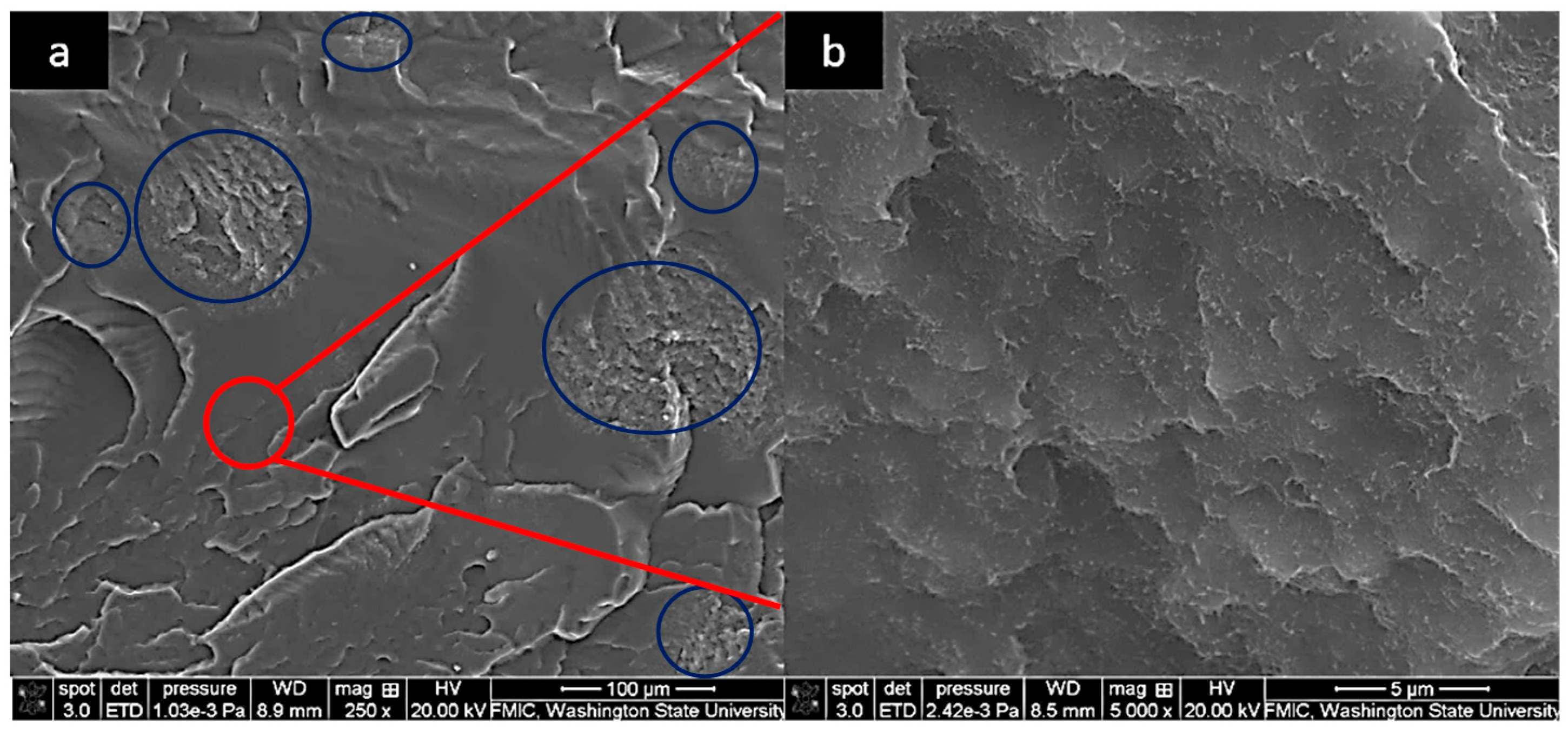
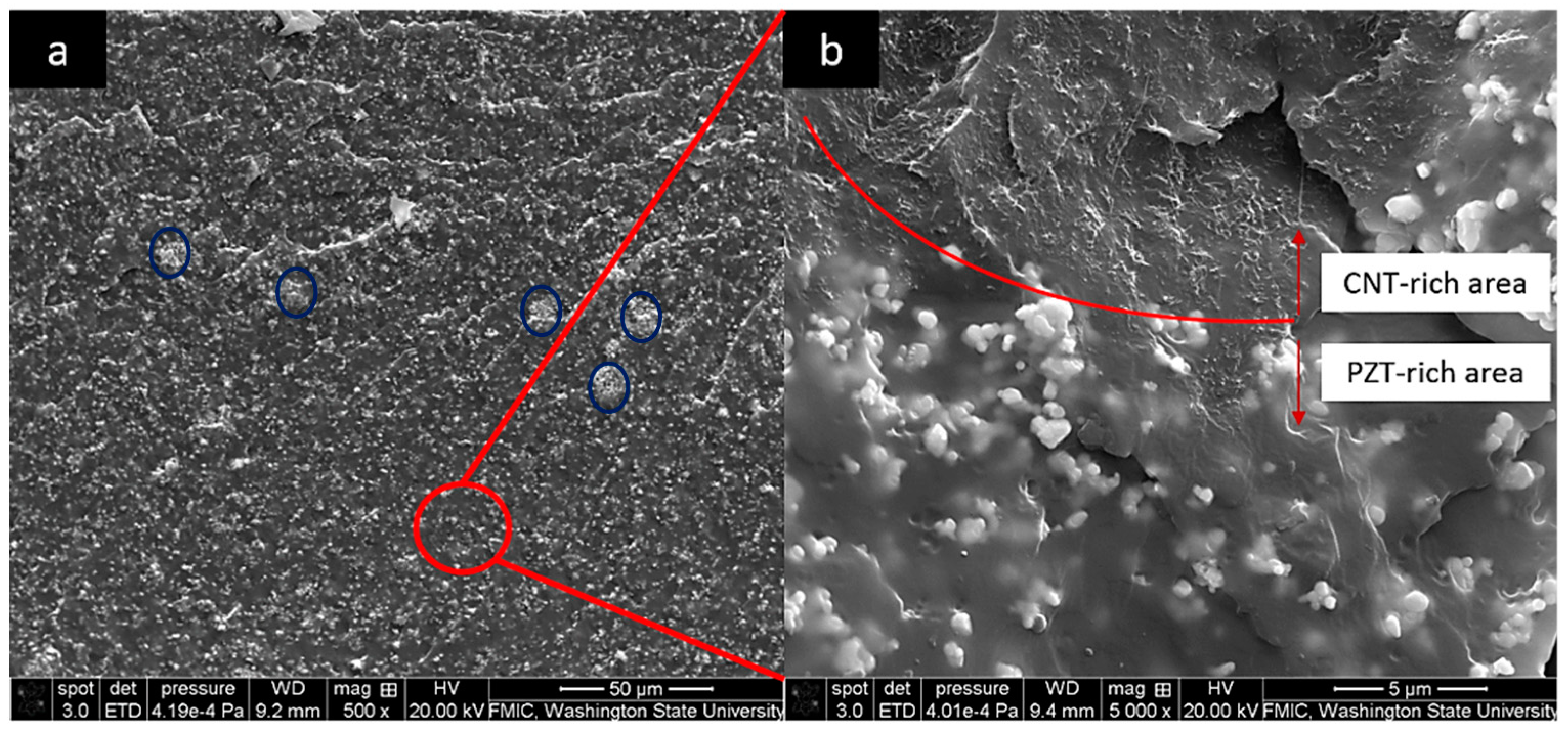
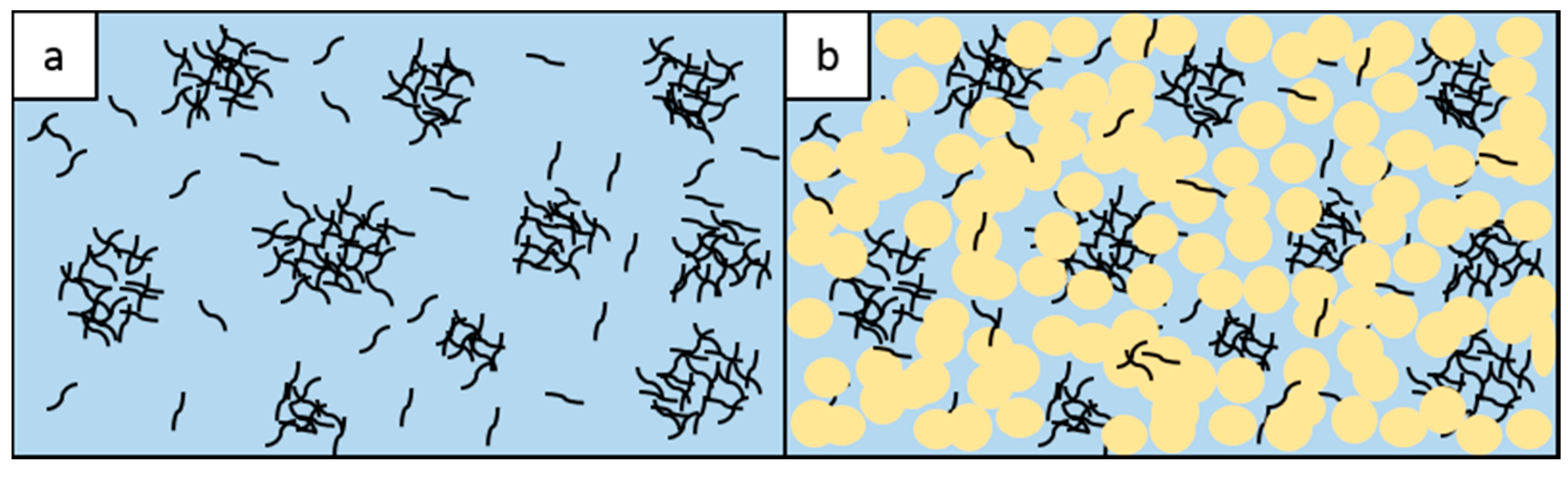
3.1. Microstructure

The dispersion of the conductive fillers within the matrix is one of the most important factors in the formation of the electrical networks and consequently the electrical properties. Figure 1 shows the morphology of TPU-1 vol% MWCNT composite, with different magnifications. In this ‘segregated structure’, MWCNTs were found in both agglomerates and dispersed states. Regions identified by blue circles in Figure 1a show the MWCNT-rich areas as agglomerates with a size of about 50–100 µm, scattered in the matrix. As Figure 1b shows a magnified image of TPU matrix, MWCNTs were also found individually dispersed in the regions away from the agglomerates.
Figure 2a depicts the dispersion of the particles in TPU/10 vol% PZT/0.3 vol% MWCNT composite. Some PZT agglomerates of less than 20 µm were observed as identified by blue circles; otherwise a good dispersion of the PZT filler was obtained. In TPU/PZT/MWCNT composites, a smaller number and size of MWCNT agglomerates were observed, which is due the fact that the micro-sized PZT filler disentangled some of the larger nanotube aggregates during mixing and interconnected the networks of MWCNTs and helped achieve a more uniform dispersion of the fillers. Studies has shown that adding a third filler to a polymer/MWCNT system can improve the dispersion of MWCNT in the matrix [58]. However, achieving near perfect dispersion would still require rigorous mixing and sonication, for an extended period of time. As a segregated structure was targeted in our composites, very limited amount of mixing was needed. At a larger magnification (Figure 2b), two different zones were observed in TPU/PZT/MWCNT microstructure: MWCNT-rich areas and PZT-rich areas. The interface between the two areas are visible in higher magnifications (Figure 2b). There are no PZT particles present in the MWCNT-rich areas, however, scattered MWCNT fillers are visible in the PZT-rich area.
Figure 3 presents a schematic illustration of TPU/MWCNT and TPU/PZT/MWCNT composites. The presence of PZT particles reduces the physical contacts between the nanotubes and prevents the formation of full electrical percolation network of MWCNTs in the TPU/PZT/MWCNT samples. The effectiveness of this barrier characteristic will depend on the amount of MWCNT and PZT fillers in the matrix. The MWCNT-rich areas can act as electrodes that surround the dielectric medium of PZT-rich areas, comprising a structure suitable for charge storage applications [30,59,60,61]. This structure could be regarded as a broken-off segregated structure. The impact of connectivity in the segregated structures has been well-studied [62,63,64,65] and is one of the most prominent methods of achieving conductive polymer composites with low contents of conductive filler.

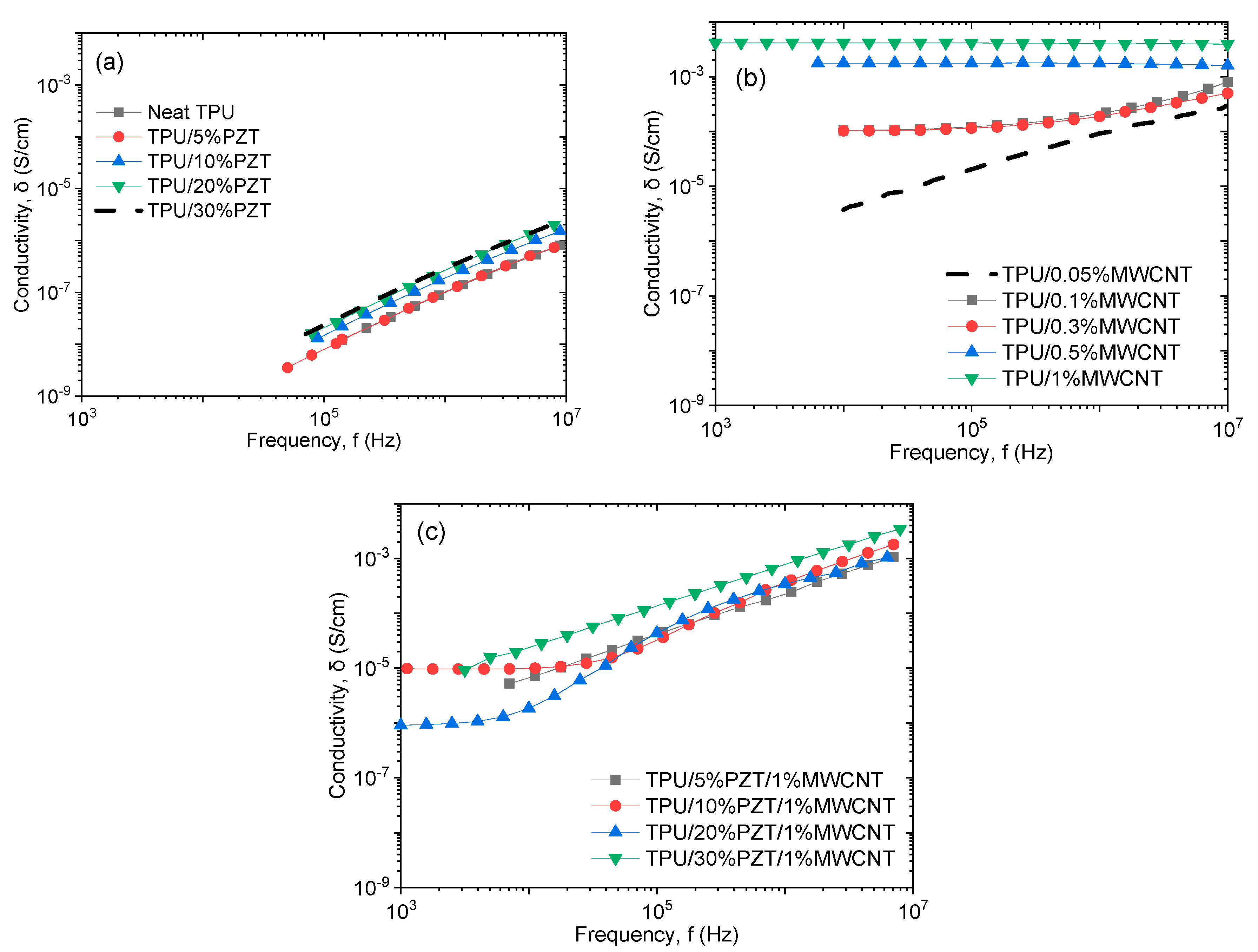
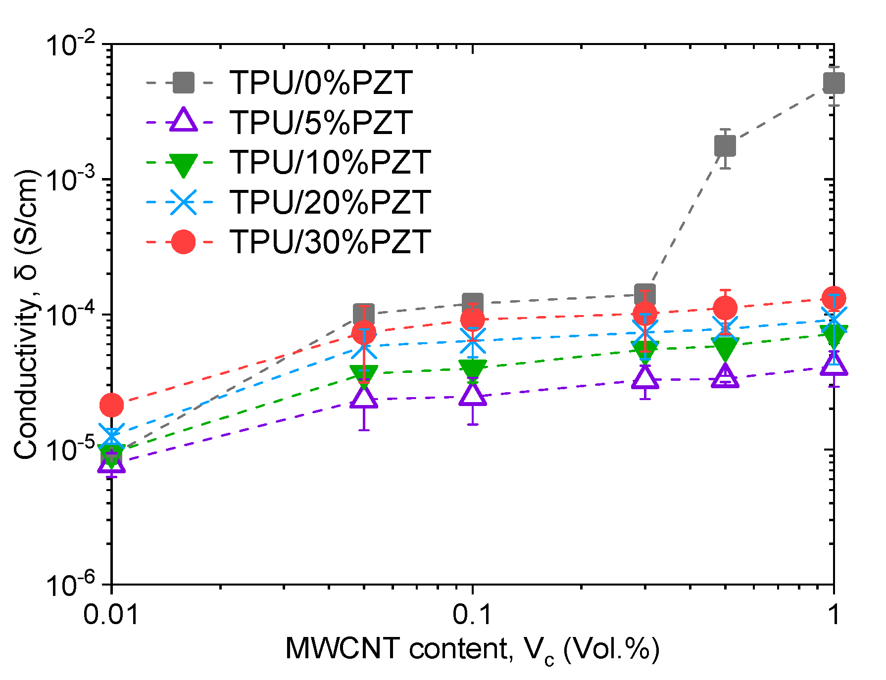
3.2. Electrical Conductivity

Figure 4a–c shows the broadband electrical conductivity, as a function of frequency, for TPU/PZT, TPU/MWCNT, and TPU/PZT/MWCNT composites, respectively. TPU/PZT composites showed a very low conductivity (Figure 4a), because both of their constituents are essentially non-conductive materials. Their conductivity showed a completely frequency dependent behavior, which is a characteristic of insulating materials. In these materials, dipole reorientation is the only conduction mechanism [66]. The conductivity increased with frequency in the entire range, since current increases with an increase in the frequency.
As seen in Figure 4b, the conductivity behavior of TPU/MWCNT composites varied as MWCNT content was increased. At MWCNT content of 0.05 vol%, the conductive fillers were not sufficiently close to one another to initiate the charge transportation mechanisms. In this case, the conductance is mainly controlled by dipole reorientation, and in this region, alternating component of conductivity (σAC) is dominant, which is frequency dependent. The composites with MWCNT contents of 0.1–0.3 vol% show a conduction behavior that is represented by σ = σDC + σAC, where σDC is the frequency-independent part of the total electrical conductivity. This law considers a critical frequency below which conductivity becomes frequency-independent, known as σDC [67]. These characteristics indicate that, unlike TPU/0.05 vol% MWCNT composite, in the samples with 0.1–0.3 vol% MWCNT, the charge transportation mechanism started to activate, and the composites are near the percolation threshold. For the TPU/MWCNT composites with MWCNT contents of 0.5 and 1 vol%, the conductivity exhibited a fully frequency-independent behavior, due to the formation of full conductive paths that facilitated the charge transfer. In other words, the insulator-conductor transition started at about 0.1 vol% MWCNT and was fully established in the 0.3–0.5 vol% MWCNT range and the composite reached its percolation threshold. This value is on the higher end of the reported percolation threshold in the literature [68,69]. It has been well stablished that entangled MWCNT fillers usually need higher concentration for percolation [70]. In this research, deconstructed segregated structures were clearly observed (Figure 1a), which is similar to the composites with entangled fillers, and therefore the higher percolation is explained.
Figure 4c shows the broadband conductivity of TPU/PZT/MWCNT composites, with different PZT contents and fixed MWCNT content at 1 vol%. Comparing with the conductivity of TPU/1 vol% MWCNT sample (constant at 3 × 10⁻³ S/cm, Figure 4b), the conductivity of all the samples containing PZT (Figure 4c) decreased. It indicates that with the addition of PZT filler, the physical contacts of MWCNTs in the conductive networks were destroyed and the direct transfer of electrons were attenuated. In the case of lack of sufficient physical contact, hopping and tunneling appear to be the main charge transport mechanisms, which was again obstructed due to the presence of relatively large PZT particles, therefore lower overall conductivity is observed [36,66,71,72]. TPU/10–20 vol%PZT/1 vol% MWCNT are the only composites showing a frequency-independent behavior in low frequencies and a frequency-dependent behavior in higher frequencies. The critical frequency is approximately 2 × 10⁴ Hz, beyond which the current from dipole reorientation overcomes the nomadic charges [30,73]. It is noted that frequency independent behavior was observed for all TPU/PZT/MWCNT composites with a MWCNT content of less than 1 vol%.
Figure 5 depicts the conductivity of TPU/PZT/MWCNT composites at various PZT and MWCNT contents, measured at a frequency of 105 Hz. The abrupt variation of conductivity, which occurs at the percolation threshold of the conductive filler, only occurs in TPU/MWCNT composites (TPU/0% PZT in Figure 5). This suggests that the addition of PZT particles hindered the formation of effective long-range percolation paths. In TPU/MWCNT composites, as the MWCNT content increased from 0.3 to 0.5 vol%, the conductivity increased from 1.01 × 10⁻⁴ to 1.77 × 10⁻³ S/cm. Many studies have been performed to examine the effect of agglomeration and morphology of conductive filler in a composite [74,75,76]. Gbaguidi et al. [75] showed the effect of the morphology and the CNT density within the agglomerates to be of great importance. Larger agglomerates have shown to be detrimental to the electrical conductivity of the composites, while smaller bundles result in composites with higher conductivity. In the composites containing PZT, an initial mild increase was observed with the addition of the first amount of MWCNT. After that, with the addition of more MWCNT, the conductivity increased gradually and slightly, between 10−5–10−4 S/cm for all contents. For instance, the conductivity changed from 7.3 × 10⁻⁴ to 9.1 × 10⁻⁴ S/cm as MWCNT content was increased 20 times (from 0.05 to 1 vol%) in TPU/20 vol% PZT/MWCNT. In addition, the conductivity of TPU/PZT/MWCNT composites slightly and consistently increased with an increase in the PZT content, which indicated the higher conductivity of PZT, compared to TPU.

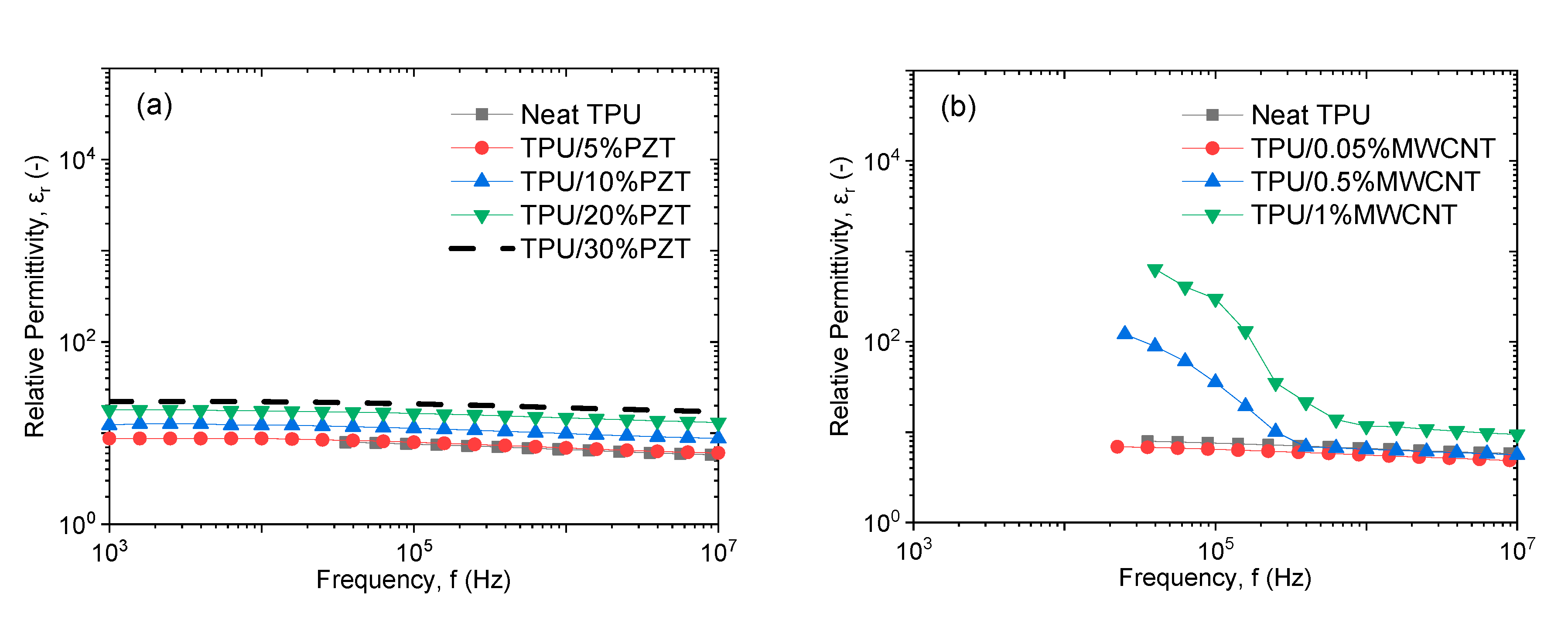
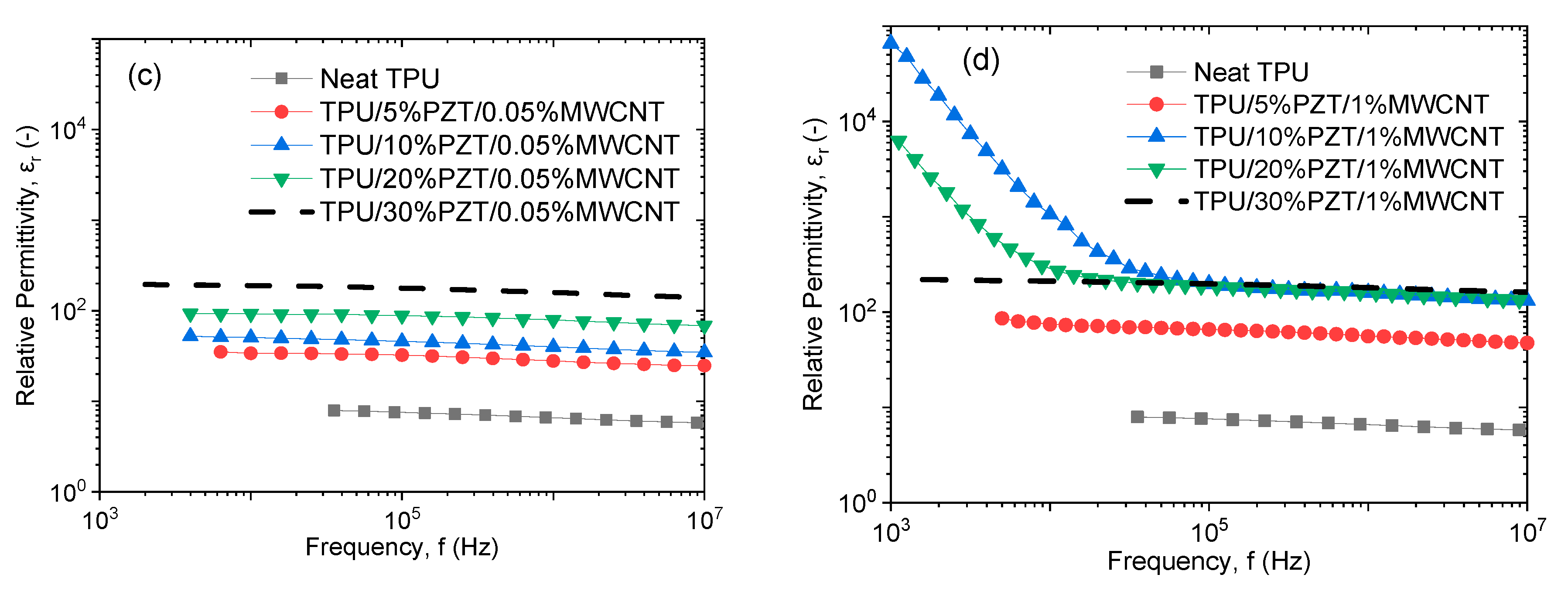
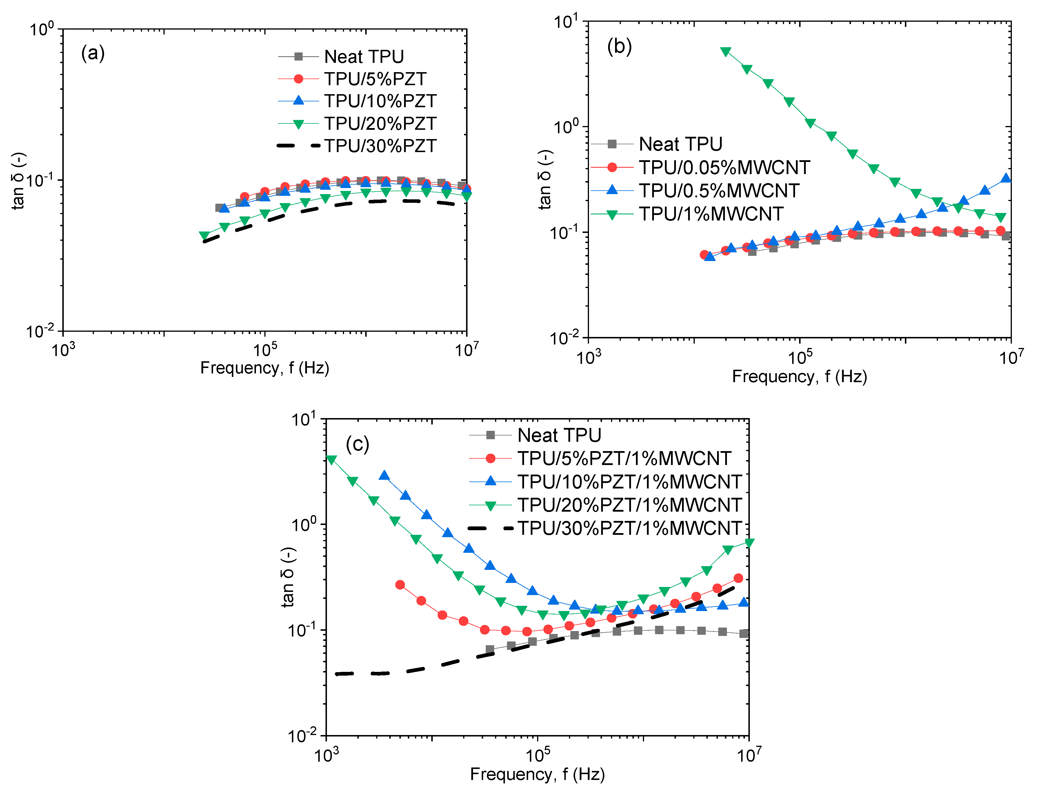
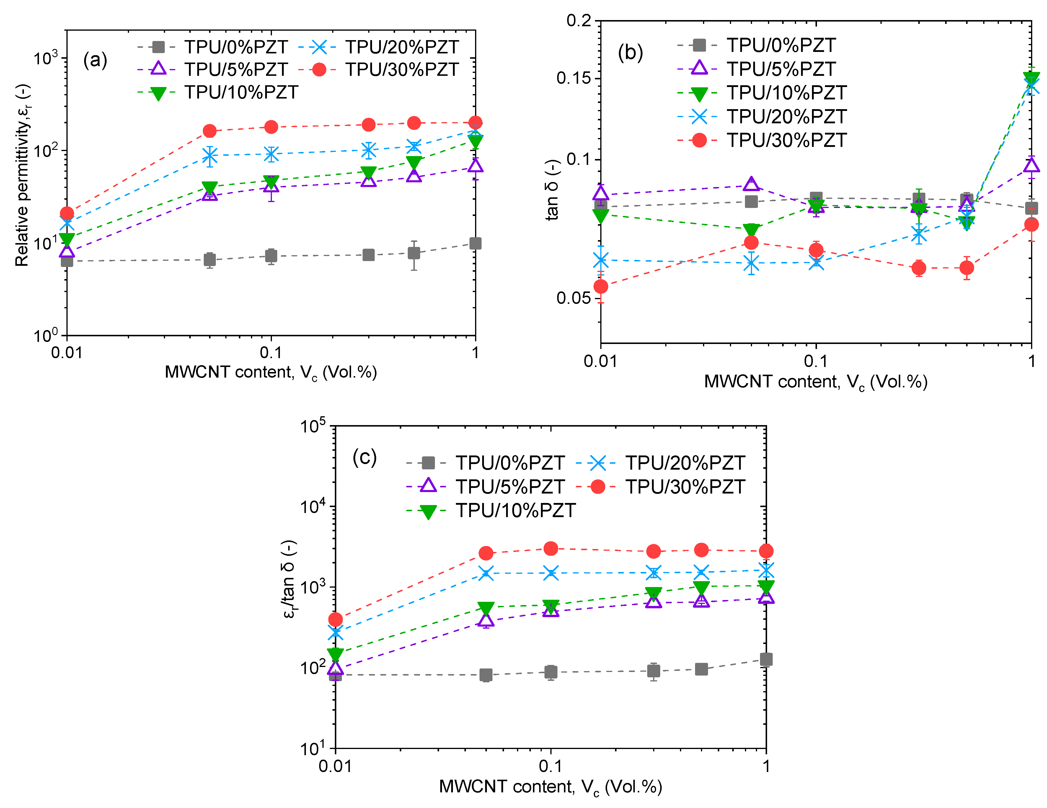
3.3. Dielectric Properties

Complex relative permittivity (ε) is a mathematically convenient way of combining the two components of the relative permittivity of a dielectric, the real part (ε′) and the imaginary part (ε″). The absolute permittivity is a measure of the ability of a material to store electric charge, as energy per unit volume, and is the ratio of electric displacement to field strength. Relative permittivity (real part of ε) is the same property of the material independent of the field strength. The imaginary part of the complex relative permittivity is called the dielectric loss factor and is the energy dissipation of a dielectric. The most commonly used parameter for expressing the lossy nature of a dielectric is the dissipation factor, otherwise known as loss tangent (tan δ), which is the ratio of the imaginary part to the real part of relative permittivity [77,78]. The combined results of these two values determines the ability of a dielectric for charge storage.
Figure 6a,b show the relative permittivity of TPU/PZT and TPU/MWCNT composites, respectively, as a function of frequency. TPU/PZT composites showed a relatively frequency-independent behavior, which is a common characteristic in dielectric composites. As the ceramic filler has a much larger permittivity compared to the matrix, most of the permittivity increase here was originated from the rule of mixture.
TPU/MWCNT composites, however, exhibited some regions of high sensitivity to frequency at high filler loads (Figure 6b). In conductive composites, all the constituents, including the matrix, filler, and their interfaces can be polarized [32,59,60,79,80]. It has been widely reported that εr of CPCs increases sharply at lower frequencies in the vicinity of percolation [1,29,35,40,47,81]. Filler and interface polarization are deemed responsible for εr increase at lower frequencies. It is suggested that the localized charge carriers overcoming the dielectric matrix barrier and the increase in the electron hopping are causing the interfacial polarization to increase, resulting in an increase in εr at lower frequencies [59]. As the insulating polymer layer thickness decreases by adding more conductive filler to the composite, the hopping mechanism becomes more efficient. At the same time, the interfacial area increases as the filler load is increased. In other words, as the MWCNT content increases, approaching the percolation threshold, interfacial polarization is signified, triggering the frequency-dependent permittivity [5]. Therefore, in TPU/PZT composites, where the permittivity is largely frequency independent, matrix and filler polarization are dominant mechanisms. Similarly, in TPU/MWCNT composites with low MWCNT contents (0.05–0.1–0.3 vol%), the MWCNT-rich areas are so far apart that the potential energy is very high and electron hopping is not feasible; therefore, εr is low and frequency-independent. In other words, interfacial polarization is not significant. On the other hand, at TPU/MWCNT composites with high MWCNT contents (0.5–1.0 vol%), the percolation threshold has been reached (Figure 4b) and the interfacial polarization is dominant and, thus, the broadband εr appears as frequency-dependent, especially at low frequencies where the relaxation times are high.
Figure 6c,d depict the broadband εr of the TPU/PZT/MWCNT composites, at 0.05 vol% and 1 vol% MWCNT content, respectively. In the composites with 0.05 vol% MWCNT, εr was relatively frequency independent and consistently increased with an increase in PZT content. As explained earlier, the frequency dependency in conductive composites occurs at the vicinity of percolation threshold, which was far from 0.05 vol% MWCNT. εr was increased from ~7 of neat TPU to ~150 for TPU/30 vol% PZT/0.05 vol% MWCNT, accounting for more than 20 times increase. The introduction of 0.05 vol% MWCNT to TPU/30 vol% PZT also accounts for a 7.5 times increase in its εr (from ~20 to ~150). It is worth noting that εr of TPU/0.05 vol% MWCNT was only ~7.4 (Figure 6b). A significant synergistic effect was thus observed upon combining PZT and MWCNT. It is believed that the unique microstructure with CNT-rich and PZT-rich areas (Figure 2 and Figure 3) acted as a micro-capacitor providing a platform for an effective polarization of PZT particles.
In TPU/PZT/MWCNT composites with 1 vol% MWCNT, εr increased enormously once PZT and MWCNT fillers were combined at certain ratios. In PZT contents of 10–20 vol%, two separate regions with different behaviors were identified, one at low frequency and the other at high frequency. In the first region, εr increased rapidly with the decrease of frequency, which is associated with the interfacial polarization of a percolated system. At higher frequencies, the available time for charge accumulation in the interfaces decrease. The large relaxation time of interfacial polarization compared to the high frequency causes the interfacial polarization effect to dwindle and eventually vanish [73]. After that, permittivity stayed constant with frequency. This is the characteristic of a conductive composite and suggests that the charge transfer functioned more effectively in 10–20 vol% PZT composites with 1 vol% MWCNT. In the case of 30 vol% PZT, the large amount of PZT filler fully blocked the conductive paths, more than that of 10 and 20 vol% PZT contents. Therefore, the interfacial polarization was weak in this composite and did not affect the broadband εr. In the case of 5 vol% PZT, the PZT content was probably not high enough to effectively disentangle some of the nanotubes in the MWCNT-rich area, as it did with a higher PZT content. Therefore, the MWCNT-rich areas were bigger, with more of the insulating TPU-PZT layer in between, and electron hopping could not be accomplished.
Figure 7a shows the broadband dielectric loss of TPU/PZT composites as a function of frequency at various PZT contents. Overall, tan δ was approximately frequency-independent and decreased with the addition of PZT. The decrease is because the dielectric loss of PZT used in this study was smaller (0.016) that that of neat TPU (0.1). Figure 7b depicts the broadband tan δ of the TPU/MWCNT composites. The dielectric loss slightly increased with the addition of MWCNT and was relatively frequency independent for MWCNT contents less than 1 vol%. In the TPU/1 vol% MWCNT samples, the conductive paths were fully formed and therefore the ohmic loss is very high. Similar to permittivity, in lower frequencies the tan δ of conductive composites increases, which is due to the high relaxation time, which causes loss of more charge carriers. Except for the TPU/1 vol% MWCNT sample, tan δ was surprisingly low. This is a result of the disassembled segregated structures and the unique morphology of these composites (Figure 1), wherein the nanotubes still help with the transfer of nomadic charge but a network is not completely formed. A relatively high and frequency-dependent tan δ hinders the application of the composite for charge storage.
Figure 7c exhibits the broadband tan δ of the TPU/PZT/MWCNT composites at 1 vol% MWCNT. The 30 vol% PZT samples show no remarkable dielectric relaxation like other percolative systems [30,59,82,83], which once again proves that all the charge transfer mechanisms were effectively blocked in these samples. However, the composites with 10–20 vol% PZT contents demonstrated a frequency-dependent behavior, which was initiated from the ohmic loss in conductive networks, as explained before. This indicates the overall influence of conductivity on the dielectric loss [73]. The composite with 5 vol% PZT had a mild frequency dependency.
Figure 8a,b show the relative permittivity and dielectric loss, respectively, for all the samples, measured at 105 Hz, as a function of MWCNT content. The relative permittivity experienced an enormous jump with the addition of 0.05 vol% MWCNT, then continued to increase with MWCNT content with a much smaller slope. The composites with a low PZT content (5–10 vol%) showed more sensitivity to the MWCNT content, because some local MWCNT networks could still be formed as the nanotube amount was increased. However, with 20–30 vol% PZT, the composites had excessive amounts of PZT filler that could disrupt the networks independent of the nanotube amount and therefore the slope of the increase was not as remarkable. For instance, TPU/10 vol% PZT composite experienced a 30% increase in εr going from 0.3 to 0.5 vol% MWCNT, while that increase for TPU/30 vol% PZT was only 4%. This suggests that the synergistic effect of PZT and MWCNT on the charge storage performance in hybrid composites depends on their relative volume content.
Another important requirement for charge storage is low dielectric loss. As seen in Figure 8b, the dielectric loss for all of the composites, except the percolative cases of 10–20 vol% PZT + 1 vol% MWCNT, remained similar to or lower than that of pure TPU. This characteristic was realized by creating MWCNT-rich and PZT-rich zones where effective micro-capacitors could be built to enhance permittivity and, at the same time, prevent the formation of conductive networks and result in low loss.
A brief review of the literature shows that many studies mainly report the permittivity of the resultant materials as a figure of merit. However, that alone does not paint a full picture as the dielectric loss is also important. Ameli et al. [5] suggested that since a high εr together with a low tan δ is the pursued combination for dielectrics, the ratio of the two (εr/tan δ) may be used as a simple figure of merit to indicate the overall performance in the material design for charge storage. Figure 8c compares this ratio for TPU/PZT, TPU/MWCNT and TPU/PZT/MWCNT samples. Overall, the massive increase of εr/tan δ from TPU/PZT and TPU/MWCNT to TPU/PZT/MWCNT samples perfectly illustrates the synergistic effect of combining PZT and MWCNT fillers in achieving the highest storage capacities. When adding 30% PZT to TPU, the εr/tan δ ratio is increased by a factor of 4.18 and the introduction of 1 vol% MWCNT to TPU enhances the εr/tan δ ratio by a factor of 1.34. However, when the two fillers are introduced concurrently with the formation of proper microstructure, εr/tan δ ratio is increased by a factor of 29.6.
Table 1 summarizes some of the recent results on the polymer-based composites for charge storage applications. The method used in this work is very simple and scalable with no further modifications needed for commercially available fillers, and the obtained results exceed the majority of previously reported values. Some works have reported values higher than those in this work, however, their works often use methods which are not suitable for large scale applications, e.g., costly and complicated methods [47,81], expensive base materials [84], or harsh experimental conditions using toxic chemicals [85].

4. Conclusions

Composites of TPU/PZT/MWCNT with 0–5–10–20–30 vol% PZT and 0–0.05–0.1–0.3–0.5–1 vol% MWCNT were fabricated. A deconstructed segregated structure exhibiting higher dielectric permittivity and lower dielectric loss is reported. All composites were prepared by solution casting. In order to provide a baseline for the TPU/PZT/MWCNT samples, composites of TPU/PZT and TPU/MWCNT were also fabricated and analyzed. Electrical conductivity, relative permittivity and dielectric loss (tan δ) of the samples were measured and the microstructure was characterized using scanning electron microscopy (SEM).
SEM micrographs revealed two main regions in the morphology of the samples: a PZT-rich region and an MWCNT-rich region. As a result of this structure, the TPU/PZT/MWCNT samples showed a lower and frequency-dependent conductivity. The conductivity of TPU/10–20 vol% PZT/1 vol% MWCNT exhibited a frequency-independent conductivity in lower frequencies, which suggested that the percolative networks had been initiated and formed. In ternary composites, only samples with high MWCNT content (0.5–1 vol%) showed a frequency-independent conductivity, which confirms the deconstructed segregated structure.
The addition of the first 0.05 vol% MWCNT to the TPU/PZT samples resulted in a massive increase in the relative permittivity, while the dielectric loss did not change to a great extent. The dielectric permittivity of all samples showed a tenfold increase, from the TPU/PZT composite to the composite with the same PZT content and 1 vol% MWCNT. The dielectric loss of almost all samples proved to be relatively independent of the fillers, however, the TPU/10–20 vol% PZT/1 vol% MWCNT samples showed an increase in tan δ, which is related to the formation of conductive networks and the increase in electrical conductivity.
The results of this work unveil a new structure with a very high relative permittivity and a low dielectric loss, which results in an optimum εr/tan δ. These composites can be effectively utilized for charge storage applications.

Author Contributions

Conceptualization: G.P. and A.A.; formal analysis: G.P. and A.A.; data curation: G.P. and N.A.; investigation: G.P. and A.A.; writing—original draft preparation: G.P.; writing—review and editing: A.A.; supervision: A.A.; project administration: A.A.; funding acquisition: A.A. All authors have read and agreed to the published version of the manuscript.

Funding

This research did not receive any specific grant from funding agencies in the public, commercial, or not-for-profit sectors.

Conflicts of Interest

The authors declare no conflict of interest.

References

  1. Kim, J.B.; Yi, J.W.; Nam, J.E. Dielectric polymer matrix composite films of CNT coated with anatase TiO2. Thin Solid Film. 2011, 519, 5050–5055. [Google Scholar] [CrossRef]
  2. Yang, T.I.; Brown, R.N.C.; Kempel, L.C.; Kofinas, P. Controlled synthesis of core-shell iron-silica nanoparticles and their magneto-dielectric properties in polymer composites. Nanotechnology 2011, 22. [Google Scholar] [CrossRef] [PubMed] [Green Version]
  3. Zhang, Y.; Wang, Y.; Deng, Y.; Li, M.; Bai, J. Enhanced dielectric properties of ferroelectric polymer composites induced by metal-semiconductor Zn-ZnO core-shell structure. ACS Appl. Mater. Interfaces 2012, 4, 65–68. [Google Scholar] [CrossRef] [PubMed]
  4. Yousefi, N.; Sun, X.; Lin, X.; Shen, X.; Jia, J.; Zhang, B.; Tang, B.; Chan, M.; Kim, J.K. Highly aligned graphene/polymer nanocomposites with excellent dielectric properties for high-performance electromagnetic interference shielding. Adv. Mater. 2014, 26, 5480–5487. [Google Scholar] [CrossRef]
  5. Ameli, A.; Nofar, M.; Park, C.B.; Pötschke, P.; Rizvi, G. Polypropylene/carbon nanotube nano/microcellular structures with high dielectric permittivity, low dielectric loss, and low percolation threshold. Carbon N. Y. 2014, 71, 206–217. [Google Scholar] [CrossRef]
  6. Dang, Z.M.; Lin, Y.H.; Nan, C.W. Novel Ferroelectric Polymer Composites with High Dielectric Constants. Adv. Mater. 2003, 15, 1625–1629. [Google Scholar] [CrossRef]
  7. Toupin, M.; Brousse, T.; Bélanger, D. Charge storage mechanism of MnO2 electrode used in aqueous electrochemical capacitor. Chem. Mater. 2004, 16, 3184–3190. [Google Scholar] [CrossRef]
  8. Simon, P.; Gogotsi, Y. Materials for electrochemical capacitors. Nat. Mater. Nat. Publ. Gr. 2008, 7, 845–854. [Google Scholar] [CrossRef] [Green Version]
  9. Zhang, L.L.; Zhao, X.S. Carbon-based materials as supercapacitor electrodes. Chem. Soc. Rev. 2009, 38, 2520–2531. [Google Scholar] [CrossRef] [PubMed]
  10. Landi, B.J.; Raffaelle, R.P.; Heben, M.J.; Alleman, J.L.; VanDerveer, W.; Gennett, T. Single Wall Carbon Nanotube—Nafion Composite Actuators. Nano Lett. 2002, 2, 1329–1332. [Google Scholar] [CrossRef] [Green Version]
  11. Wu, G.; Hu, Y.; Liu, Y.; Zhao, J.; Chen, X.; Whoehling, V.; Plesse, C.; Nguyen, G.T.M.; Vidal, F.; Chen, W. Graphitic carbon nitride nanosheet electrode-based high-performance ionic actuator. Nat. Commun. 2015, 6. [Google Scholar] [CrossRef] [PubMed] [Green Version]
  12. Guo, W.; Guo, Y. Giant axial electrostrictive deformation in carbon nanotubes. Phys. Rev. Lett. 2003, 91, 3–6. [Google Scholar] [CrossRef] [PubMed]
  13. Smela, E. Conjugated polymer actuators for biomedical applications. Adv. Mater. 2003, 15, 481–494. [Google Scholar] [CrossRef]
  14. Shahinpoor, M.; Kim, K.J. Ionic polymer-metal composites: IV. Industrial and medical applications. Smart Mater. Struct. 2005, 14, 197–214. [Google Scholar] [CrossRef]
  15. Li, N.; Huang, Y.; Du, F.; He, X.; Lin, X.; Gao, H.; Ma, Y.; Li, F.; Chen, Y.; Eklund, P.C. Electromagnetic Interference (EMI) shielding of single-walled carbon nanotube epoxy composites. Nano Lett. 2006, 6, 1141–1145. [Google Scholar] [CrossRef]
  16. Ameli, A.; Jung, P.U.; Park, C.B. Electrical properties and electromagnetic interference shielding effectiveness of polypropylene/carbon fiber composite foams. Carbon N. Y. 2013, 60, 379–391. [Google Scholar] [CrossRef]
  17. Chung, D.D.L. Carbon materials for structural self-sensing, electromagnetic shielding and thermal interfacing. Carbon N. Y. 2012, 50, 3342–3353. [Google Scholar] [CrossRef]
  18. Yu, A.; Hu, H.; Bekyarova, E.; Itkis, M.E.; Gao, J.; Zhao, B.; Haddon, R.C. Incorporation of highly dispersed single-walled carbon nanotubes in a polyimide matrix. Compos. Sci. Technol. 2006, 66, 1190–1197. [Google Scholar] [CrossRef]
  19. Kwon, J.; Kim, H. Comparison of the properties of waterborne polyurethane/multiwalled carbon nanotube and acid-treated multiwalled carbon nanotube composites prepared by in situ polymerization. J. Polym. Sci. Part A Polym. Chem. 2005, 43, 3973–3985. [Google Scholar] [CrossRef]
  20. Mattiat, O.E. Ultrasonic Transducer Materials; Springer Science & Business Media: Berlin, Germany, 2013. [Google Scholar]
  21. Zhang, S.; Xia, R.; Shrout, T.R. Lead-free piezoelectric ceramics vs. PZT? J. Electroceram. 2007, 19, 251–257. [Google Scholar] [CrossRef]
  22. Arbatti, M.; Shan, X.; Cheng, Z. Ceramic-polymer composites with high dielectric constant. Adv. Mater. 2007, 19, 1369–1372. [Google Scholar] [CrossRef]
  23. Lu, J.; Wong, C.P. Polymer nanocomposites with high dielectric strength and high frequency performance for emdedded passive applications. In Proceedings of the PORTABLE-POLYTRONIC 2008—2nd IEEE International Interdisciplinary Conference on Portable Information Devices and the 2008 7th IEEE Conference on Polymers and Adhesives in Microelectronics and Photonics, Garmish-Partenkirchen, Germany, 17–20 August 2008. [Google Scholar] [CrossRef]
  24. Jayasundere, N.; Smith, B.V. Dielectric constant for binary piezoelectric 0-3 composites. J. Appl. Phys. 1993, 73, 2462–2466. [Google Scholar] [CrossRef]
  25. Decker, R.; Heinrich, M.; Tröltzsch, J.; Rhein, S.; Gebhardt, S.; Michaelis, A.; Kroll, L. Development and characterization of piezo-active polypropylene compounds filled with PZT and CNT. In Proceedings of the 5th Scientific Symposium CRC/Transregio, Dresden, Germany, 14–16 September 2015; pp. 59–64. [Google Scholar]
  26. Vyas, P.; Prajapat, R.; Manmeeta, A.; Saxena, D. Study of dielectric and piezoelectric properties of CNT reinforced PZT-PVA 0-3 composite. AIP Conf. Proc. 2016, 1728, 020341. [Google Scholar] [CrossRef]
  27. Guan, X.; Zhang, Y.; Li, H.; Ou, J. PZT/PVDF composites doped with carbon nanotubes. Sens. Actuators A Phys. 2013, 194, 228–231. [Google Scholar] [CrossRef]
  28. Sakamoto, W.K.; Marin-Franch, P.; Das-Gupta, D.K. Characterization and application of PZT/PU and graphite doped PZT/PU composite. Sens. Actuators A Phys. 2002, 100, 165–174. [Google Scholar] [CrossRef]
  29. Zhou, W.; Kou, Y.; Yuan, M.; Li, B.; Cai, H.; Li, Z.; Chen, F.; Liu, X.; Wang, G.; Chen, Q.; et al. Polymer composites filled with core@double-shell structured fillers: Effects of multiple shells on dielectric and thermal properties. Compos. Sci. Technol. 2019, 181. [Google Scholar] [CrossRef]
  30. Dang, Z.M.; Wang, L.; Yin, Y.; Zhang, Q.; Lei, Q.Q. Giant dielectric permittivities in functionalized carbon-nanotube/electroactive-polymer nanocomposites. Adv. Mater. 2007, 19, 852–857. [Google Scholar] [CrossRef]
  31. Gao, J.; Asadi, K.; Xu, J.B.; An, J. Controlling of the surface energy of the gate dielectric in organic field-effect transistors by polymer blend. Appl. Phys. Lett. 2009, 94. [Google Scholar] [CrossRef] [Green Version]
  32. Ameli, A.; Wang, S.; Kazemi, Y.; Park, C.B.; Pötschke, P. A facile method to increase the charge storage capability of polymer nanocomposites. Nano Energy 2015, 15, 54–65. [Google Scholar] [CrossRef]
  33. Arjmand, M.; Mahmoodi, M.; Park, S.; Sundararaj, U. An innovative method to reduce the energy loss of conductive filler/polymer composites for charge storage applications. Compos. Sci. Technol. 2013, 78, 24–29. [Google Scholar] [CrossRef]
  34. Wang, B.; Liu, L.; Huang, L.; Chi, L.; Liang, G.; Yuan, L.; Gu, A. Fabrication and origin of high-k carbon nanotube/epoxy composites with low dielectric loss through layer-by-layer casting technique. Carbon N. Y. 2015, 85, 28–37. [Google Scholar] [CrossRef]
  35. Arjmand, M.; Sadeghi, S.; Khajehpour, M.; Sundararaj, U. Carbon nanotube/graphene nanoribbon/polyvinylidene fluoride hybrid nanocomposites: Rheological and dielectric properties. J. Phys. Chem. C 2017, 121, 169–181. [Google Scholar] [CrossRef]
  36. Ameli, A.; Arjmand, M.; Pötschke, P.; Krause, B.; Sundararaj, U. Effects of synthesis catalyst and temperature on broadband dielectric properties of nitrogen-doped carbon nanotube/polyvinylidene fluoride nanocomposites. Carbon N. Y. 2016, 106, 260–278. [Google Scholar] [CrossRef]
  37. Shen, Y.; Lin, Y.; Li, M.; Nan, C.W. High dielectric performance of polymer composite films induced by a percolating interparticle barrier layer. Adv. Mater. 2007, 19, 1418–1422. [Google Scholar] [CrossRef]
  38. Czerw, R.; Guo, Z.; Ajayan, P.M.; Sun, Y.P.; Carroll, D.L. Organization of Polymers onto Carbon Nanotubes: A Route to Nanoscale Assembly. Nano Lett. 2001, 1, 423–427. [Google Scholar] [CrossRef]
  39. Yao, S.H.; Yuan, J.K.; Dang, Z.M.; Bai, J. High dielectric performance of three-component nanocomposites induced by a synergetic effect. Mater. Lett. 2010, 64, 2682–2684. [Google Scholar] [CrossRef]
  40. Zhu, J.; Ji, X.; Yin, M.; Guo, S.; Shen, J. Poly (vinylidene fluoride) based percolative dielectrics with tunable coating of polydopamine on carbon nanotubes: Toward high permittivity and low dielectric loss. Compos. Sci. Technol. 2017, 144, 79–88. [Google Scholar] [CrossRef]
  41. Wan, Y.J.; Zhu, P.L.; Yu, S.H.; Yang, W.H.; Sun, R.; Wong, C.P.; Liao, W.H. Barium titanate coated and thermally reduced graphene oxide towards high dielectric constant and low loss of polymeric composites. Compos. Sci. Technol. 2017, 141, 48–55. [Google Scholar] [CrossRef]
  42. Carponcin, D.; Dantras, E.; Dandurand, J.; Aridon, G.; Levallois, F.; Cadiergues, L.; Lacabanne, C. Electrical and piezoelectric behavior of polyamide/PZT/CNT multifunctional nanocomposites. Adv. Eng. Mater. 2014, 16, 1018–1025. [Google Scholar] [CrossRef]
  43. Shayesteh Zeraati, A.; Mirkhani, S.A.; Sundararaj, U. Enhanced Dielectric Performance of Polymer Nanocomposites Based on CNT/MnO2 Nanowire Hybrid Nanostructure. J. Phys. Chem. C 2017, 121, 8327–8334. [Google Scholar] [CrossRef]
  44. Ma, M.; Wang, X. Preparation, microstructure and properties of epoxy-based composites containing carbon nanotubes and PMN-PZT piezoceramics as rigid piezo-damping materials. Mater. Chem. Phys. 2009, 116, 191–197. [Google Scholar] [CrossRef]
  45. McCall, W.R.; Kim, K.; Heath, C.; La Pierre, G.; Sirbuly, D.J. Piezoelectric nanoparticle-polymer composite foams. ACS Appl. Mater. Interfaces 2014, 6, 19504–19509. [Google Scholar] [CrossRef]
  46. Zeraati, A.S.; Arjmand, M.; Sundararaj, U. Silver Nanowire/MnO2 Nanowire Hybrid Polymer Nanocomposites: Materials with High Dielectric Permittivity and Low Dielectric Loss. ACS Appl. Mater. Interfaces 2017, 9, 14328–14336. [Google Scholar] [CrossRef]
  47. Zhu, X.; Yang, J.; Dastan, D.; Garmestani, H.; Fan, R.; Shi, Z. Fabrication of core-shell structured Ni@BaTiO3 scaffolds for polymer composites with ultrahigh dielectric constant and low loss. Compos. Part A Appl. Sci. Manuf. 2019, 125, 105521. [Google Scholar] [CrossRef]
  48. McNally, T.; Boyd, P.; McClory, C.; Bien, D.; Moore, I.; Millar, B.; Davidson, J.; Carroll, T. Recycled carbon fiber filled polyethylene composites. J. Appl. Polym. Sci. 2008, 107, 2015–2021. [Google Scholar] [CrossRef]
  49. Han, H.; Wang, X.; Wu, D. Mechanical properties, morphology and crystallization kinetic studies of bio-based thermoplastic composites of poly(butylene succinate) with recycled carbon fiber. J. Chem. Technol. Biotechnol. 2013, 88, 1200–1211. [Google Scholar] [CrossRef]
  50. Ameli, A.; Nofar, M.; Wang, S.; Park, C.B. Lightweight polypropylene/stainless-steel fiber composite foams with low percolation for efficient electromagnetic interference shielding. ACS Appl. Mater. Interfaces 2014, 6, 11091–11100. [Google Scholar] [CrossRef]
  51. Chen, C.S.; Chen, W.R.; Chen, S.C.; Chien, R. Der Optimum injection molding processing condition on EMI shielding effectiveness of stainless steel fiber filled polycarbonate composite. Int. Commun. Heat Mass Transf. 2008, 35, 744–749. [Google Scholar] [CrossRef]
  52. Amjadi, M.; Pichitpajongkit, A.; Lee, S.; Ryu, S.; Park, I. Highly stretchable and sensitive strain sensor based on silver nanowire-elastomer nanocomposite. ACS Nano 2014, 8, 5154–5163. [Google Scholar] [CrossRef]
  53. Pompe, G.; Pohlers, A.; Pötschke, P.; Pionteck, J. Influence of processing conditions on the multiphase structure of segmented polyurethane. Polymer 1998, 39, 5147–5153. [Google Scholar] [CrossRef]
  54. Jagadish, K.; Srikantaswamy, S.; Byrappa, K.; Shruthi, L.; Abhilash, M.R. Dispersion of Multiwall Carbon Nanotubes in Organic Solvents through Hydrothermal Supercritical Condition. J. Nanomater. 2015, 2015. [Google Scholar] [CrossRef] [Green Version]
  55. Pang, H.; Xu, L.; Yan, D.X.; Li, Z.M. Conductive polymer composites with segregated structures. Prog. Polym. Sci. 2014, 39, 1908–1933. [Google Scholar] [CrossRef]
  56. Kazemi, Y.; Ramezani Kakroodi, A.; Ameli, A.; Filleter, T.; Park, C.B. Highly stretchable conductive thermoplastic vulcanizate/carbon nanotube nanocomposites with segregated structure, low percolation threshold and improved cyclic electromechanical performance. J. Mater. Chem. C 2018, 6, 350–359. [Google Scholar] [CrossRef]
  57. Timsit, R.S. Electrical contact resistance_ properties of stationary interfaces. In Proceedings of the IEEE Transactions on Components and Packaging Technologies, Arlington, VA, USA, 26–28 October 1998; Volume 22, pp. 85–98. [Google Scholar] [CrossRef]
  58. Xiao, Y.J.; Wang, W.Y.; Lin, T.; Chen, X.J.; Zhang, Y.T.; Yang, J.H.; Wang, Y.; Zhou, Z.W. Largely Enhanced Thermal Conductivity and High Dielectric Constant of Poly(vinylidene fluoride)/Boron Nitride Composites Achieved by Adding a Few Carbon Nanotubes. J. Phys. Chem. C 2016, 120, 6344–6355. [Google Scholar] [CrossRef]
  59. Jiang, M.J.; Dang, Z.M.; Bozlar, M.; Miomandre, F.; Bai, J. Broad-frequency dielectric behaviors in multiwalled carbon nanotube/rubber nanocomposites. J. Appl. Phys. 2009, 106. [Google Scholar] [CrossRef] [Green Version]
  60. Yuan, J.K.; Yao, S.H.; Dang, Z.M.; Sylvestre, A.; Genestoux, M.; Bai, J. Giant dielectric permittivity nanocomposites: Realizing true potential of pristine carbon nanotubes in polyvinylidene fluoride matrix through an enhanced interfacial interaction. J. Phys. Chem. C 2011, 115, 5515–5521. [Google Scholar] [CrossRef]
  61. Dang, Z.M.; Yao, S.H.; Yuan, J.K.; Bai, J. Tailored dielectric properties based on microstructure change in batio 3-carbon nanotube/polyvinylidene fluoride three-phase nanocomposites. J. Phys. Chem. C 2010, 114, 13204–13209. [Google Scholar] [CrossRef]
  62. Gupta, S.; Runqing, O.U.; Gerhardt, R.A. Effect of the fabrication method on the electrical properties of poly(acrylonitrile-co-butadiene-co-styrene)/carbon black composites. J. Electron. Mater. 2006, 35, 224–229. [Google Scholar] [CrossRef]
  63. Kyrylyuk, A.V.; Hermant, M.C.; Schilling, T.; Klumperman, B.; Koning, C.E.; Van Der Schoot, P. Controlling electrical percolation in multicomponent carbon nanotube dispersions. Nat. Nanotechnol. 2011, 6, 364–369. [Google Scholar] [CrossRef]
  64. Jurewicz, I.; Worajittiphon, P.; King, A.A.K.; Sellin, P.J.; Keddie, J.L.; Dalton, A.B. Locking carbon nanotubes in confined lattice geometries—A route to low percolation in conducting composites. J. Phys. Chem. B 2011, 115, 6395–6400. [Google Scholar] [CrossRef]
  65. Linares, A.; Canalda, J.C.; Cagiao, M.E.; Ezquerra, T.A. Conducting nanocomposites based on polyamide 6,6 and carbon nanofibers prepared by cryogenic grinding. Compos. Sci. Technol. 2011, 71, 1348–1352. [Google Scholar] [CrossRef] [Green Version]
  66. Ameli, A.; Kazemi, Y.; Wang, S.; Park, C.B.; Pötschke, P. Process-microstructure-electrical conductivity relationships in injection-molded polypropylene/carbon nanotube nanocomposite foams. Compos. Part A Appl. Sci. Manuf. 2017, 96, 28–36. [Google Scholar] [CrossRef]
  67. Antunes, M.; Mudarra, M.; Velasco, J.I. Broad-band electrical conductivity of carbon nanofibre-reinforced polypropylene foams. Carbon N. Y. 2011, 49, 708–717. [Google Scholar] [CrossRef]
  68. Koerner, H.; Liu, W.; Alexander, M.; Mirau, P.; Dowty, H.; Vaia, R.A. Deformation-morphology correlations in electrically conductive carbon nanotube—Thermoplastic polyurethane nanocomposites. Polymer 2005, 46, 4405–4420. [Google Scholar] [CrossRef]
  69. Gojny, F.H.; Wichmann, M.H.G.; Fiedler, B.; Kinloch, I.A.; Bauhofer, W.; Windle, A.H.; Schulte, K. Evaluation and identification of electrical and thermal conduction mechanisms in carbon nanotube/epoxy composites. Polymer 2006, 47, 2036–2045. [Google Scholar] [CrossRef]
  70. Dang, Z.M.; Yuan, J.K.; Zha, J.W.; Zhou, T.; Li, S.T.; Hu, G.H. Fundamentals, processes and applications of high-permittivity polymer-matrix composites. Prog. Mater. Sci. 2012, 57, 660–723. [Google Scholar] [CrossRef]
  71. Chekanov, Y.; Ohnogi, R.; Asai, S.; Sumita, M. Electrical properties of epoxy resin filled with carbon fibers. J. Mater. Sci. 1999, 34, 5589–5592. [Google Scholar] [CrossRef]
  72. Sichel, E.K.; Gittleman, J.I.; Sheng, P. Transport properties of the composite material carbon-poly(vinyl chloride). Phys. Rev. B 1978, 18, 5712–5716. [Google Scholar] [CrossRef] [Green Version]
  73. Arjmand, M.; Ameli, A.; Sundararaj, U. Employing Nitrogen Doping as Innovative Technique to Improve Broadband Dielectric Properties of Carbon Nanotube/Polymer Nanocomposites. Macromol. Mater. Eng. 2016, 301, 555–565. [Google Scholar] [CrossRef]
  74. Gong, S.; Zhu, Z.H.; Meguid, S.A. Carbon nanotube agglomeration effect on piezoresistivity of polymer nanocomposites. Polymer 2014, 55, 5488–5499. [Google Scholar] [CrossRef]
  75. Gbaguidi, A.; Namilae, S.; Kim, D. Stochastic percolation model for the effect of nanotube agglomeration on the conductivity and piezoresistivity of hybrid nanocomposites. Comput. Mater. Sci. 2019, 166, 9–19. [Google Scholar] [CrossRef]
  76. Li, J.; Ma, P.C.; Chow, W.S.; To, C.K.; Tang, B.Z.; Kim, J.K. Correlations between percolation threshold, dispersion state, and aspect ratio of carbon nanotubes. Adv. Funct. Mater. 2007, 17, 3207–3215. [Google Scholar] [CrossRef]
  77. Alger, M. Polymer Science Dictionary; Springer Science & Business Media: Berlin, Germany, 1996. [Google Scholar]
  78. Tamura, R.; Lim, E.; Manaka, T.; Iwamoto, M. Analysis of pentacene field effect transistor as a Maxwell-Wagner effect element. J. Appl. Phys. 2006, 100. [Google Scholar] [CrossRef]
  79. Mahmoodi, M.; Arjmand, M.; Sundararaj, U.; Park, S. The electrical conductivity and electromagnetic interference shielding of injection molded multi-walled carbon nanotube/polystyrene composites. Carbon N. Y. 2012, 50, 1455–1464. [Google Scholar] [CrossRef]
  80. Panwar, V.; Park, J.O.; Park, S.H.; Kumar, S.; Mehra, R.M. Electrical, dielectric, and electromagnetic shielding properties of polypropylene-graphite composites. J. Appl. Polym. Sci. 2010, 115, 1306–1314. [Google Scholar]
  81. Chen, J.; Wang, X.; Yu, X.; Yao, L.; Duan, Z.; Fan, Y.; Jiang, Y.; Zhou, Y.; Pan, Z. High dielectric constant and low dielectric loss poly(vinylidene fluoride) nanocomposites: Via a small loading of two-dimensional Bi2Te3@Al2O3 hexagonal nanoplates. J. Mater. Chem. C 2018, 6, 271–279. [Google Scholar] [CrossRef]
  82. Wang, L.; Dang, Z.M. Carbon nanotube composites with high dielectric constant at low percolation threshold. Appl. Phys. Lett. 2005, 87, 2003–2006. [Google Scholar] [CrossRef]
  83. Kazemi, Y.; Kakroodi, A.R.; Wang, S.; Ameli, A.; Filleter, T.; Pötschke, P.; Park, C.B. Conductive network formation and destruction in polypropylene/carbon nanotube composites via crystal control using supercritical carbon dioxide. Polymer 2017, 129, 179–188. [Google Scholar] [CrossRef]
  84. Hu, T.; Juuti, J.; Jantunen, H.; Vilkman, T. Dielectric properties of BST/polymer composite. J. Eur. Ceram. Soc. 2007, 27, 3997–4001. [Google Scholar] [CrossRef]
  85. Wu, Y.; Lin, X.; Shen, X.; Sun, X.; Liu, X.; Wang, Z.; Kim, J.K. Exceptional dielectric properties of chlorine-doped graphene oxide/poly (vinylidene fluoride) nanocomposites. Carbon N. Y. 2015, 89, 102–112. [Google Scholar] [CrossRef]
  86. Xie, L.; Huang, X.; Yang, K.; Li, S.; Jiang, P. “Grafting to” route to PVDF-HFP-GMA/BaTiO3 nanocomposites with high dielectric constant and high thermal conductivity for energy storage and thermal management applications. J. Mater. Chem. A 2014, 2, 5244–5251. [Google Scholar] [CrossRef]
  87. Yang, T.I.; Kofinas, P. Dielectric properties of polymer nanoparticle composites. Polymer (Guildf.) 2007, 48, 791–798. [Google Scholar] [CrossRef]
  88. Luo, S.; Shen, Y.; Yu, S.; Wan, Y.; Liao, W.H.; Sun, R.; Wong, C.P. Construction of a 3D-BaTiO3 network leading to significantly enhanced dielectric permittivity and energy storage density of polymer composites. Energy Environ. Sci. 2017, 10, 137–144. [Google Scholar] [CrossRef]
  89. Akhina, H.; Mohammed Arif, P.; Gopinathan Nair, M.R.; Nandakumar, K.; Thomas, S. Development of plasticized poly (vinyl chloride)/reduced graphene oxide nanocomposites for energy storage applications. Polym. Test. 2019, 73, 250–257. [Google Scholar] [CrossRef]
  90. Ji, W.; Deng, H.; Sun, C.; Fu, Q. Nickel hydroxide as novel filler for high energy density dielectric polymer composites. Compos. Sci. Technol. 2019, 172, 117–124. [Google Scholar] [CrossRef]
  91. Zhang, Y.; Zhang, C.; Feng, Y.; Zhang, T.; Chen, Q.; Chi, Q.; Liu, L.; Li, G.; Cui, Y.; Wang, X.; et al. Excellent energy storage performance and thermal property of polymer-based composite induced by multifunctional one-dimensional nanofibers oriented in-plane direction. Nano Energy 2019, 56, 138–150. [Google Scholar] [CrossRef]
  92. Yang, J.; Zhu, X.; Wang, H.; Wang, X.; Hao, C.; Fan, R.; Dastan, D.; Shi, Z. Achieving excellent dielectric performance in polymer composites with ultralow filler loadings via constructing hollow-structured filler frameworks. Compos. Part A Appl. Sci. Manuf. 2020, 131, 105814. [Google Scholar] [CrossRef]
Figure 1. SEM micrograph of TPU-1 vol% MWCNT composite with two different magnifications: (a) showing the MWCNT-rich areas identified by blue circles and (b) a magnified MWCNT-poor area, showing the dispersion of individual MWCNTs (the white speckles are individual MWCNT).
Jcs 04 00137 g001
Figure 2. SEM micrographs of TPU-10 vol% PZT-0.3 vol% MWCNT samples showing: (a) the overall PZT dispersion with some agglomerates identified by blue circles and (b) a MWCNT-rich area surrounded by a PZT-rich area with a distinctive boundary.
Jcs 04 00137 g002
Figure 3. Schematic illustrations of (a) TPU/MWCNT composites, showing the MWCNT-rich zones and (b) TPU/PZT/MWCNT composites, showing MWCNT-rich and PZT-rich zones.
Jcs 04 00137 g003
Figure 4. Broadband electrical conductivity as a function of frequency for (a) TPU/PZT, (b) TPU/MWCNT, and (c) TPU/PZT/1 vol% MWCNT composites.
Jcs 04 00137 g004
Figure 5. Electrical conductivity of TPU/PZT/MWCNT composites as a function of MWCNT contents at various PZT contents, measured at a frequency of 105 Hz.
Jcs 04 00137 g005
Figure 6. Broadband relative permittivity of (a) TPU/PZT, (b) TPU/MWCNT, (c) TPU/PZT/0.05 vol% MWCNT, and (d) TPU/PZT/1 vol% MWCNT.
Jcs 04 00137 g006aJcs 04 00137 g006b
Figure 7. Broadband dielectric loss of (a) TPU/PZT, (b) TPU/MWCNT, and (c) TPU/PZT/1 vol% MWCNT composites.
Jcs 04 00137 g007
Figure 8. (a) Relative permittivity, εr, (b) dielectric loss, tan δ, and (c) εr/tan δ ratio of TPU/PZT/MWCNT composites as a function of MWCNT content at various PZT loadings at a frequency of 105 Hz.
Jcs 04 00137 g008
Table 1. A summary of dielectric parameters in recent literature.
WorkMatrixFillerFrequency (Hz)Relative Permittivity (-)Dielectric Loss (-)ɛ/tan δ
This workTPU30 vol% PZT + 1.0 vol% MWCNT105200.90.0722790.3
This workTPU30 vol% PZT + 0.05 vol% MWCNT105162.50.0662462.2
Kim [1]Bisphenol A diglycidyl ether (DGEBA)CNT (coated with TiO2):5 wt%109100.06166.6
Ameli [5]PPMWCNT:0.34 vol%102300.06500.0
Dang [30]Polyvinylidene fluoride (PVDF)MWCNT (modified with TFP): 0.08 vol%1035502.2250.0
Wang [34]EpoxyMWCNT: 0.5 wt%14650.7664.2
Arjmand [35]PVDFMWCNT-graphene nanoribbon: 1.5 wt%10341.40.9145.4
Ameli [36]PVDFNitrogen-doped CNT: 3.5 wt%10323.120.05462.4
Zhu [40]PVDFPolydopamine coated CNT: 0.2 wt%1033150.35900.0
Wan [41]PVDFBarium titanate coated graphene oxide: 8 wt%10356.30.058970.6
Decker [25]PP70 wt% PZT + 1.4 wt%CNT 103802.334.8
Vyas [26]PVA50 vol% PZT + 1 vol% CNT103650.1650
Ma [44]Epoxy1.5 g CNT per 100 g epoxy + 100 g PZT-PMN per 100 g epoxy106300.3100
Guan [27]PVDF50 vol% PZT + 0.8 vol% CNT10395701.36
Sakamoto [28]PU49 vol% PZT + 1% graphite105300.837.5
Zeraati [46]PMMASilver/manganese dioxide nanowire: 2–1 vol%8.2 × 109640.31206.4
Arjmand [73]PVDFNitrogen-doped CNT: 1 wt%103220.03733.3
Zeraati [43]PVDFCNT-MnO2NW: 3–4.5 wt%8.2 × 10950.60.772.2
Wu [85]PVDFChlorinated graphene oxide: 0.2 vol%1033640.0774727.2
Xie [86]PVDF-HFP-GMA Barium titanate: 30 vol%106200.16125.0
Hu [84]Cyclic olefin copolymer (COC)Barium strontium titanate: 25 vol%1097.30.00233173.9
Yang [87]S-SEBSTitanium dioxide: 6.4%10430.01300.0
Luo [88]Epoxy3D Barium titanate: 30 vol%1032000.141428.5
Chen [81]PVDFCore-shell Bi2Te3@Al2O3: 10 vol%1031400.052800.0
Zhu [47]EpoxyCore-shell Ni@BaTiO3 scaffolds (4 vol%)10463970.04159,925
Akhina [89]PVCGraphene oxide: 2.66 vol%10310.831.159.4
Ji [90]PVDFNi(OH)2: 10 wt%10219.60.066297
Zhou [29]PVDFCore@double-shell Al: 50 wt%103370.05740
Zhang [91]PVDFAligned BZCT@SiO2: 3 vol%101160.03533.3
Yang [92]Epoxyhollow structured BaTiO3: 5 vol%104220.032687.5

