A Review of Recent Advances in Emerging Alternative Heating and Cooling Technologies


School of the Built Environment and Architecture, London South Bank University, London SE1 0AA, UK
*
Authors to whom correspondence should be addressed.
Energies 2021, 14(2), 502; https://0-doi-org.brum.beds.ac.uk/10.3390/en14020502
Submission received: 14 December 2020
/
Revised: 11 January 2021
/
Accepted: 14 January 2021
/
Published: 19 January 2021
(This article belongs to the Special Issue Alternative and Emerging Cooling and Heating Technologies)
Abstract
:The heating and cooling industry underpins everything we do, e.g., manufacturing, commercial and residential applications. Many of these applications invariably use mechanical refrigeration technologies, consequently contributing significantly to the environmental impacts of the refrigeration, air conditioning, and heat pump (RACHP) industry both through direct and indirect emissions of CO2. To reduce these emissions, research and development worldwide aim to improve the performance of conventional systems and the development of new refrigeration technologies of potentially much lower environmental impacts. As we transition to a low carbon economy, there are sizable environmental and economic benefits from developing and using efficient, innovative, low carbon heating and cooling technologies that reduce energy use and carbon emissions. This paper provides an up-to-date and comprehensive critical review and evaluation of recent advances in emerging alternative heating and cooling technologies that have the potential to reduce the environmental impacts of refrigeration in the RACHP sector. The paper highlights the basic working principle of operation, its main applications, the challenges and opportunities in penetrating the market. The paper also highlights further research and development needed to accelerate the development and adoption of these alternative refrigeration technologies by the sector. Most of the technologies reviewed have a Technology Readiness Level (TRL) of 3–4, except electrocaloric technology which is less ready compared to its counterparts with a TRL of 1–2 at this stage. Furthermore, most technologies have capacities ranging between a few kilowatts to a maximum of 7 kW with a coefficient of performance COP between 1 and 10 reported in the literature.
1. Introduction
A significant amount of energy used in the UK is used primarily for heating, cooling, and lighting in buildings, and is responsible for around 47% of the country’s CO2 emissions. Adopting efficient, low carbon technologies with better systems could result in considerable environmental and economic benefits. Although vapour compression cycles, since invented, have achieved extensive success in refrigeration and air conditioning, but the ascending prices of electricity and environmental concerns which are emphasising the need to reducing carbon footprint, have underlined the interest in developing new technologies that could eventually be economically and environmentally more viable than the conventional vapour compression systems.
Most of the previous studies, in this regard, separately addressed different technologies from different aspects. A few papers have compared two technologies. For instance, Ozbalt et al. compared two caloric technologies by studying them under certain circumstances, and thereafter they drew their conclusion [1]. The only study which looked at certain technologies was done in 2010 by a group of research at Brunel University; they looked at different technologies from a food applications point of view. Tassou et al. studied eight technologies and how each technology could be used in food applications [2]. In the last five years, there has not been a paper reviewing new technologies and summarizing them; and what had been done in the past was not specifically covering emerging alternative technologies, hence comes the importance of this paper. This paper is a continuation of the previous efforts, and it presents a comprehensive review of seven emerging alternative cooling and heating technologies. It starts with a brief description of each technology and its basic working principles followed by a review of the challenges and state of development of the technology, applications, and advantages and disadvantages. It also highlights the economic and environmental assessment of the technologies.
2. Magnetic Refrigeration
2.1. Basic Working Principles
Magnetic refrigeration works on the principle of exposing paramagnetic materials to a magnetic field generated, preferably, by rare earth magnets as they have a stronger magnetic field. Paramagnetic materials have a high susceptibility to magnetic fields. They don’t retain the magnetic field when the external source is removed. They have paramagnetic properties due to the unpaired electrons, i.e., Magnesium, Lithium, Tantalum, etc.
Rare earth magnets are preferred over other magnets for their high magnetic anisotropy which gives the material high magnetic coercivity (resistance to being demagnetised), as well as for their high magnetic moment as they have many unpaired electrons which gives the material a high saturation magnetization. The maximum energy density is in a direct correlation with the saturation magnetization which means the magnetic field generated from a material like Neodymium significantly high when compared to a magnetic field generated by an ordinary magnet by volume. For instance, the magnetic field density produced by a 100 g of Neodymium magnet can be achieved by 1.8 kg of other ordinary magnets.
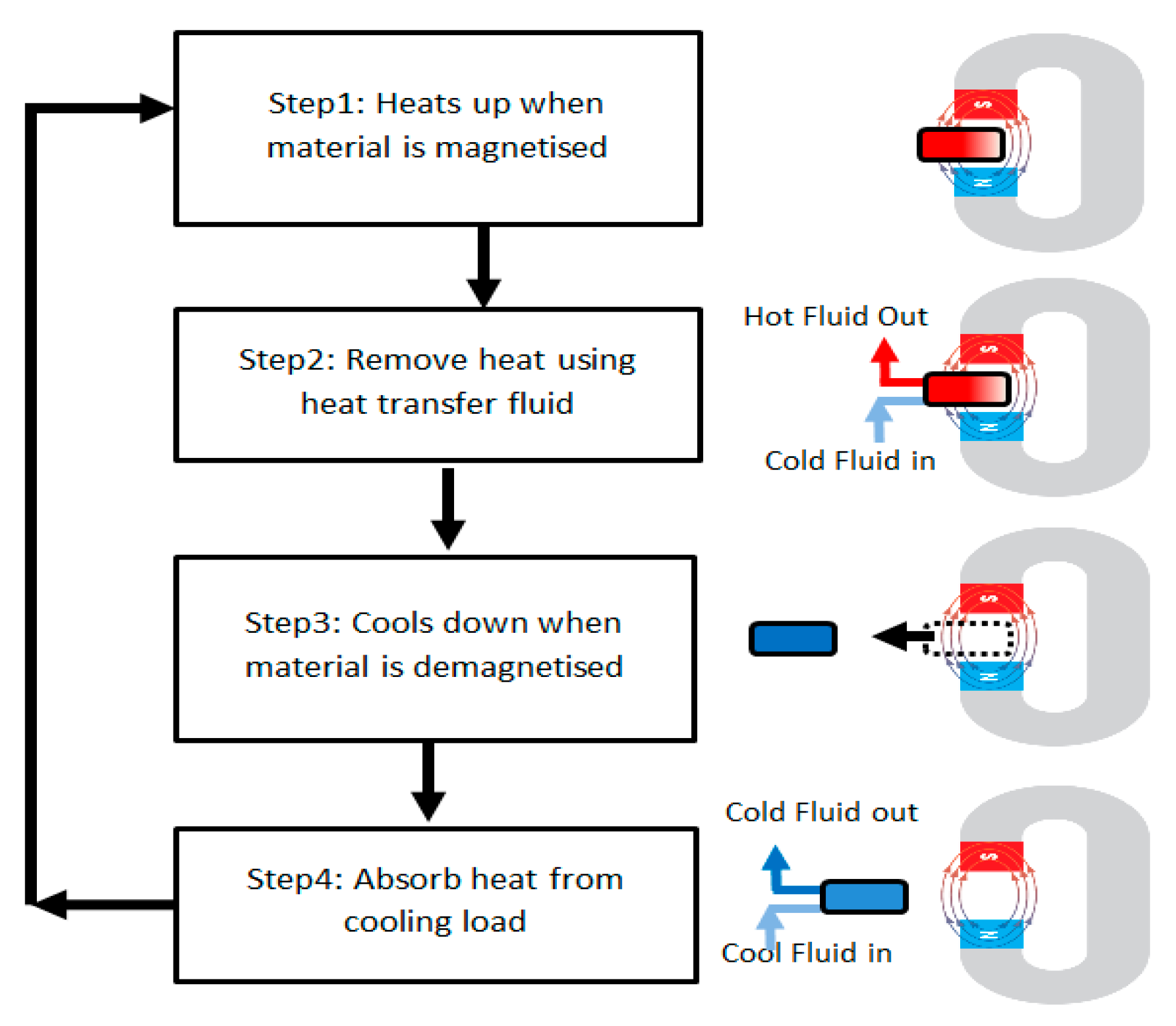
When a paramagnetic material is exposed to a magnetic field, the molecules in the material start to spin in one direction and align themselves in an orderly pattern. This process makes the material have a low specific heat capacity and expels heat. When the magnetic field is removed, the molecules go back to their original random pattern, causing the material to have a high specific heat capacity and therefore absorb heat. Figure 1 depicts the basic working principle of the technology.
2.2. Working Materials
Magnetocaloric materials can generally be found in two main divisions which are: Rare earth materials (containing crystalline and free crystalline) and Amorphous materials. The only pure rare-earth containing crystalline material is Gadolinium whose magnetocaloric effect can be improved by alloying it with other elements like Ferrum (Fe), Niobium (Nb) or Boron (B) and many other different chemical elements. Among all rare-earth containing materials, there are certain families whose good magnetocaloric effect attracted attention like: (1) A composition of Gadolinium (Gd) with Silicon (Si) and Germanium (Ge) with certain concentrations (2) a composition of Lanthanum (La) with Ferrum (Fe), Silicon (Si) and Aluminum (Al) and Rhenium (Re) containing compounds; (3) Laves phases materials. The rare-earth free crystalline elements Ferrum (Fe), Cobalt (Co) and Nickel (Ni) showed a fairly good Magnetocaloric Effect (MCE). In the other hand, the Amorphous materials which are classified into Gd-based and Fe-based show excellent properties in terms of their low hysteresis, low eddy currents, and their resistance to corrosion [3].
Magnetocaloric effect in materials can be enhanced by material processing such as hydrogenation, metal foam structuring and annealing at different temperatures to increase the grains size. Franco et al. through experiments, claimed that annealing at higher temperatures delivers better results [3]. A high magnetocaloric effect is absolutely crucial in developing a magnetocaloric device, and so far, all the materials which have high MCE mainly depend on rare earth magnets, which 95% of their production is in China that has placed restrictions on rare earth magnets export.
2.3. Challenges and State of Development
Since the discovery of giant magnetocaloric effect by Pecharsky and Gscheidner in 1997, the research and development of this technology have been very active. Several (near room temperature) magnetic refrigeration prototypes were reported in many countries like the UK, USA, Japan, China and several European countries.
Aprea et al. made a comparison between R134a refrigerant and two different geometries (porous and flat plate) of a 2 Tesla (T) active magnetic regenerator (AMR) using different rare earth magnets and water as heat transfer fluid (HTF) [4]. Aprea et al. used a mathematical model to calculate the COP and then made a comparison between (AMR) cycle, and the traditional vapour compression cycle (VC), and the comparison was carried out in terms of , where:
where, is the coefficient of performance for the vapour compression system and is the coefficient of performance of the active magnetic regenerator, which is calculated as the ratio between the cooling power the regenerator produces Q to the work input to the device W [4,5].
Aprea et al.’s results showed first-order magnetic transition (FOMT) materials (Gd5Si2Ge2, MnAs0.9Sb0.1, and MnAs0.95Sb0.05) have better energetic performances when compared to vapour compression systems, and they achieved . While the second-order magnetic transition (SOMT) materials (God, Gd0.95Dy0.05, and Gd0.9Tb0.1) achieved . The experiments also revealed that the geometry of the AMR plays an important role, and it was reported that the COP of the AMR cycle is better in the low mass flow rate when in a porous media regenerator, and the COP is better in the high flow mass in a flat plate regenerator [4].
Olsen et al. published results from a numerical study on two active magnetic refrigeration models. The first model was designed utilising plates of graded Gd-like which achieved a maximum cooling power of 10 kW/L, and the second model used thermal switch for controlling the heat flow in the magnetocaloric material (MCM) and the model achieved a maximum cooling power/volume of 34 kW/L [6]. In the same year, Gatti et al. introduced a hydraulic solution. The idea was implemented in a prototype with two linear stages with the ability to control the flow rate and heat transfer fluid’s velocity. Gatti et al. achieved a temperature span of 33 K at a volume flow rate of 6.6 and a frequency of 1 Hz, the test was run for a 1000 s and a heating load of 3.7 to 6.9 W was achieved. Then, by reducing the volume flow rate and the frequency (6.6 , 0.55 Hz), respectively, a temperature span of 38 K was achieved [7].
Govindaraju et al. developed a time-dependent mathematical model of an AMR for large scale cooling (>1 kW). Govindaraju et al., through modelling, identified the characteristics required to achieve a cooling capacity as large as 50 kW. These characteristics are the diameter of Gd, room temperature, load temperature, utilization factor, frequency, the mass of MCM and magnetic field. They found that the cooling capacity is in direct relation with the mass of MCM, and the performance of AMR depends on the magnetic field as well as it could be improved by using a low viscosity and high heat capacity HTF. It was also found that the magnetic field and temperature span govern the COP and the utilisation factor controls the temperature gradient [8].
Albertini et al. did some experiments on a prototype using Gadolinium as refrigerant and water as a medium for heat exchange. Albertini et al. carried out a preliminary investigation using a computational fluid dynamics analysis on a novel regenerator, and the results showed that the temperature distribution of Gadolinium decreased cycle by cycle which highlighted the effect of the regeneration [9].
Franco et al. carried out comprehensive research and studied the magnetocaloric materials and their characteristics and directed the future research towards the discovery of new phases with a high magnetocaloric response. As well as looking at the microstructure of the material to achieve the engineering techniques of the refrigeration application [3].
The geometry of the material used, could affect the performance of the AMR. Li et al. in 2019 assessed the performance of a gadolinium-based regenerator in a rotary type magnetic refrigerator by altering the geometry of the gadolinium elements used in the AMR. They filled the AMR by three different shapes of Gadolinium pieces (Flakes, spheres and plates). From experiments, they achieved 14.8 K temperature span from flakes-filled AMR, and the temperature span dropped to 10.8 K when the AMR was filled with sphere shape gadolinium pieces achieving a cooling power of 10 W [10]. In the same year, Huang et al. developed an experimental rotary magnetic refrigerator prototype named FAME cooler, and they used to assess how different MCM could affect the performance in a realistic environment. The AMR of their device was filled in with 1.18 kg sphere shape gadolinium pieces which produced 0.875 T. The FAME cooler achieved 162.4 W of cooling power at no temperature lift, and it achieved a temperature lift of 11.6 K at zero cooling power. The maximum COP reached by the device was 1.85 [11].
He et al. have constructed a device that allows testing three-cycle modes, which are series, parallel and cascade. The core MCM used is a 277 g of Gadolinium along with two Neodymium Iron Boron (NdFeB) permanent magnets which provide a magnetic field intensity of 1.5 T. From the study, they have found that the parallel mode improves the cooling power while the series mode increases the temperature lift. In contrast, the cascade mode has the highest temperature lift with a cooling capacity slightly less than the parallel mode’s one. These results have been drawn as the temperature lifts achieved are 5.66 K, 4.16 K, and 7.35 K in the series, parallel and cascade cycles, respectively; and the corresponding cooling powers are 29.02, 39.47, and 34.79 W/kg. The study has not included the COP for each mode [12].
Many other prototypes were reported, and the highest capacity reported was 844 W, and the COP ranged from 0.2 to 9.4 depending on the conditions under which the test was conducted. Therefore, this technology can be used only for a limited number of application and in small-scale cooling/heating products.
The subject of Magnetocaloric is vast, and the materials are not available yet as the existing materials are expensive and not abundant in the world (except in China), which makes the materials not suitable to be used for commercial devices. More focus should be put on machine design optimization using multidisciplinary support in order to achieve a design for Industrial applications. One of the critical factors that has not been researched is the materials ageing and its effect on the performance of the system and the device’s life span.
2.4. Applications
Magnetocaloric Refrigeration (MR) technology can be used for refrigerators working at room temperature as well as for cryogenic temperatures and in small cooling and heating devices. Since 1953, there have been many attempts at building a working MR refrigerator. Still, none achieved an outcome which could be commercialized, as the highest cooling load achieved so far was less than one kilowatt, and it was achieved by using an 890 g Gd magnet which produced 1.5 Tesla (T). Which roughly means, in the best scenario, one kilogram of rare earth magnet can produce one kW of cooling/heating, bearing in mind that the density of Gadolinium is . This technology with its current state of development cannot be used for air conditioning in buildings.
2.5. Advantages and Disadvantages
This technology is still under research and its selling points when fully developed will be the fact that it is environmentally friendly, easy to switch between cooling and heating, run by the direct current which means less voltages, no working fluid as water could be used as heat transfer fluid, high reliability, no moving part although this point is debatable as the magnet needs to rotate to alternatively expose the two plates to the magnetic field and last but not least the technology is claimed to have unlimited life span which is also highly debatable, as there is no enough research on the material aging. On the other hand, this technology is extremely expensive, and it cannot be used for large scale with current fabrication technologies.
3. Electrocaloric Refrigeration
3.1. Basic Working Principles
Line and Glass described the electrocaloric effect as a change of a crystal’s temperature that happens when applying an adiabatic electric field. Electrocaloric refrigeration works on the principle of applying an electric field on certain materials with certain dielectric properties. The applied electrical field makes the material change its temperature by changing the dipolar state, which results in a change in entropy which causes the material to expel heat. When the electric field is removed, the dipolar order returns to its original state, and thus the material absorbs heat, and this characteristic is called the electrocaloric effect (ECE). Kobeno and Kurtschatov in 1930 experimentally investigated the ECE for the first time. Despite this characteristic was discovered more than a hundred years ago, its microscopic physical picture is still not fully understood. However, on the macroscopic level, the ECE phenomenon can be described as entropy exchange between two entropy reservoirs [13]. Figure 2 depicts the basic working principle of the technology.
3.2. Working Materials
ECE can be found in ferroelectrics, relaxor ferroelectrics (which are organic and inorganic disordered ferroelectrics) and Aniferroelectric. The lead-based relaxor ferroelectrics are the most studied materials, but due to environmental issues, the focus shifted to lead-free electrocaloric materials like K0.5Na0.5NbO3–SrTiO3 (KNN–STO) ceramics and BaTiO3-based ferroelectrics [13]. ECE has been known for too long, but it never drew the attention for commercial applications due to its small magnitude, until Mischenko et al. discovered the giant ECE. A giant ECE of ΔT = 12 K was reported in Piezoelectric (PZT) thin films as well as in ferroelectric copolymer and terpolymer at near room temperature. Perovskites family showed high electrocaloric effect especially film relaxor perovskites as they achieved a temperature lift of 45 K, which made this family among the most studied. There are many other different families who showed different levels of electrocaloric effects which include, but are not limited to, lithium niobate and lithium tantalite, hexagonal manganites, tungsten bronzes, pyrochlores, layered oxides, barium fluorides, molybdates, boracites, colemanite, halides, antimony sulphide iodides, triglycine sulphate, and ferroelectric polymers [14,15]. Electrocaloric performance can be predicted by different measurements such as zero-field entropy change, pyroelectric coefficient, dielectric constant and ferroelectric loops.
Among the above-mentioned families, Perovskites and ferroelectric polymers are promising for electrocaloric refrigeration for their high ECE, and they work at cure temperature of 83–763 K and 350 K respectively. However, all these families are lead-based materials which make their future use very nebulous, as lead is classified by European Chemical Agency (ECHA) as a very toxic material to aquatic life and can cause long-term damage in people like cancer, kidneys failure, anemia, or even death [16].
Since the lead-based materials cannot have a future in electromagnetic refrigeration, research has shifted focus onto finding less harmful and more environmentally friendly lead-free materials. Among the materials which have been studied is lead-free ferroelectric materials (with three different concentration for Sn, x = 0.02, 0.05 & 0.10) which is a composition of Barium, Strontium, Titanate, and Stannum. This composition showed ΔT = 0.188 K under an electric field of 7 kV/cm [17].
Barium Strontium Titanate is widely studied, as it has an ECE potential. Zaitouni et al. conducted experiments and tested different compositions and concentrations, and they got the highest ECE with a temperature difference of ΔT = 0.34 K under an electric field of 15 kV/cm while the highest ECE of Barium Strontium Titanate was ΔT = 0.207 K under an electric field of 10 kV/cm. Which means to lift the temperature by 1 K, an electric field of 44 kV/cm or 0.44 kV/m is needed, provided the material used is BaSrTiSnO [17].
The density of Barium Strontium Titanate depends on Strontium’s content, so if Sr increases from 0 to 0.5, the overall density of the compound drops from [18]. Barium Strontium Titanate is available from different online suppliers for 12–23 $ per kg. The electrocaloric effect of any material is governed by the amount of the applied voltages, which is challenging, as it may be accompanied by the dielectric breakdown and current leakage. Therefore, if the required temperature difference (ΔT) is determined, then the required electric voltage can be determined, so can the size of the material, and thereafter, the price could be determined.
3.3. Challenges and State of Development
Ozbalt et al. compared between magnetocaloric and electrocaloric. They carried out the comparison through studying the effect of electric field and mass-flow on a thin-film electrocaloric ceramic refrigerator, by applying three different electric fields of 32.9, 58.3 and 77.4 MV/m, and by altering the water’s mass-flow between 0.003 and 0.2 kg/s under different frequencies. Whereas the magnetic field intensity in the Magnetocaloric regenerator was fixed at 1 T. It was found that Electrocaloric refrigeration at higher temperature spans achieves higher theoretical COP; the COP drops with a higher electric field, but on the other hand, the cooling power increases. Whereas Magnetocaloric regenerator achieves higher cooling power with a smaller temperature span [1].
Aprea et al. used a 2D multi-physics model to test different ECMs working as refrigerants for an active electrocaloric refrigerator (AER) at room temperature under electric fields ranged between 0 to 100 MV/m. They altered the mass flow rate of water to study the effect it can have on the performance. Their results showed that the best material for Electrocaloric refrigeration is PLZT ceramics, as it achieved a temperature span of 23 K, a cooling load of 893 W and a maximum COP of 11.2. It was also found that there is a direct correlation between mass flow rate and cooling power [19].
Molin et al. tested two different multilayers ceramic (MLC) each of nine layers of and respectively, and they found that the electrocaloric response is independent of the layer’s thickness. Molin et al. got an electrocaloric temperature change of 2.7 K when applying an external electric field of and the result showed the significance of multilayer relaxor ferroelectrics [20].
Aprea et al. carried out a comparison between electrocaloric refrigerator working with an electrocaloric regeneration cycle (AER) using water as secondary fluid, and a commercial R134a refrigeration plant. The simulation showed that the COP is the highest when using thin films of PLZT materials and it also showed that using specific materials such as (PVDF n.s. 70 MV/m, PST 77.4 MV/m, PVDF n.s. 100 MV/m) could produce higher greenhouse gas emissions compared to vapour compression system [21].
Following the restriction of lead-based materials by the European Union (due to their high toxicity), the focus shifted onto lead-free materials. Shi et al. investigated lead-free ceramics (BCZT-Li) by citrate method which improved the electrical performance and made it possible to get a large electrocaloric effect [22].
Aprea et al. carried out a comparison between caloric materials operating in an active caloric regenerator using a numerical 2D model. The experiments were carried out on an AMR cycle with a frequency of 1.25 Hz, varying the mass flux between . The experiments identified the most promising caloric materials for the four different technologies in question (Magneto, Electro, Elasto, and Baro). The comparison was carried out using three main indexes which are COP, Cooling Power and Temperature Span [23]. Aprea et al. concluded that the magnetocaloric materials (MCMs) including Gd (which is the best among its counterparts), have the weakest performance and that is due to the limited magnetic field produced by the permanent magnets. While the electrocaloric materials (ECMs), especially PLZT class, showed better performance as it achieved a temperature span of 40 K with a cooling load between 1 kW to 1.8 kW and a maximum COP of 15, which makes it applicable for a wider scope of applications [23].
Lu et al. studied the phenomenon of Joule heating, and they concluded that this phenomenon significantly reduces the refrigeration ability of electrocaloric materials at high electric field and temperature [24]. Guvenc et al. looked at the influence aging has on electrocaloric effect on Lithium doped Barium Titanate ceramic and they concluded that aging creates defect polarisation and its effect could be reduced by Lithium (Li) doping [25]. Lu et al. synthesised the samples in question by using the conventional solid-state synthesis and found that aging changes the hysteresis loop and lowers the polarisation. It was also found that aging has a negative and positive effect on the polarisation. Lu et al., through their work, concluded that it is possible to engineer the electrocaloric effect by using appropriate defect strategies [24]. Planzik et al., on the other hand, studied the effect of the ECM’s hysteresis and the electric energy recovery on the device’s performance. They looked at these effects through a 2D numerical model that studies the characteristics of an AER’s device. The results showed that the efficiency of the device is majorly affected by the degree of the electric energy recovery and the hysteresis of the ECM used. As a consequence, Planzik et al. highly recommended considering these two factors when designing an EC device [26]. Based on the current situation, electrocaloric technology is considered a promising alternative to the vapour compression system, but it still needs a lot of research before it could achieve cooling and heating loads that will allow the technology to compete in the market.
3.4. Applications
All the Electrocaloric Refrigeration (ECR) prototypes and demonstrators designed and manufactured so far have not achieved high cooling/heating power nor a high-temperature span/difference. For instance, we found that Planzik et al. designed a cooling device using bulk ceramics, and they could achieve a temperature difference of 3.4 K at room temperature. While Zhang et al. achieved a temperature span of 5 K. The united Technology Research Centre UTRC designed a gas-cooling electrocaloric device which reached a temperature difference of 14 K. Under the current state of development of ECR technology, it can be used in air conditioning of small size buildings as well as it can only be used in limited applications such as wearable coolers and cooling and heating vehicle seats [26,27].
3.5. Advantages and Disadvantages
Electrocaloric refrigeration technology depends on the electric field, which is easy and cheap to generate compared to the magnetic field. ECR has no moving parts (compressor free), which means less maintenance cost. On the other hand, the available EC materials are the lead-based materials which are toxic and can cause complicated health issues; therefore more research into lead-free materials is needed; it was also proven that certain ECMs emit greenhouse gases. One of the issues with ECR is that the large electric field causes stress in the internal structure and that results in chemical degradation and electromechanical breakdown. Therefore, the fatigue life (aging) of the ECM needs more research and studying. It is not possible to apply a high electric field with low voltage on bulk materials unlike on thin films, but the energy that could be stored in thin films is very small, and that comes at the expense of the cooling power.
4. Thermoelectric Refrigeration
4.1. Basic Working Principles
Peltier first reported thermoelectric generator in 1834, and it is a solid-state semiconductor-based electronic device capable of converting a voltage input into a temperature difference which can be used for either heating or cooling. It also produces DC electrical current if a temperature difference is applied to the device.
The device contains ceramic substrates (Alumina, Beryllium oxide, or Aluminium nitride), p-type & n-type semiconductor elements, diffusion barrier (Ni) on the end of each element, and copper interconnects. The P & N semiconductors are wired electrically in series and thermally in parallel. When the current passes through the semiconductor, the lower side cools down, and the heat flows in reverse heating the top side of the thermoelectric cooler (TEC). Below Figure 3 depicts the basic working principle of the technology.
4.2. Working Materials
The classification of thermoelectric materials depends on their dimensions, as they are divided into low-dimensional thermoelectric materials and bulk thermoelectric materials. The performance of thermoelectric materials depends solely on the Seebeck coefficient (relation between thermoelectric voltage and temperature difference; best materials would have a Seebeck of 1.0), low thermal conductivity and high electrical conductivity. Thermoelectric materials come in chemical compounds of Bismuth Telluride ), Lead Telluride , Silicon Germanium and Cobalt Antimonite . Two of these families are not environmentally friendly, as is lead-containing and therefore it is toxic; the other family contains Antimonite which causes respiratory irritation as well as skin issues. It was also found that bulk materials of phonon-glass electron-crystal have a good thermoelectric potential as their electrons have high mobility [28].
4.3. Challenges and State of Development
Thermoelectric generators (TEC) require a large DC current as well as an AC/DC converter which make them costly and have low energy. As a consequence of that, they are mainly used in applications where reliability, silence and convenience are more important than the economic aspect. TEC has mainly been used in military, aerospace, industrial and scientific applications, but it was also introduced in small applications such as PC processors, car seats temperature control and portable food and beverage storages. TEC has low COPs of between 0.3 and 0.8 depending on the application as well as the ambient in which the application is operating [28].
Navarro-Peris et al. ran experiments to investigate the energy output when the temperature difference is maintained by natural convention. The thermoelectric generator was tested by means of varying the hot and cold sides temperatures, and the results showed that the energy out is low. Therefore this method was recommended not to be used [29].
Pietrzyk et al. presented a new factor for thermoelectric module design (B-factor) which is defined as the ratio of the area specified for thermoelectric material to the area of the module. Pietrzyk et al. developed a theoretical model and validated the model using three months’ experimental data. They concluded that the module’s performance is in a reverse relation with the contact resistance, and to ensure good performance, the leg’s (P&N semiconductor pair) length should be increased [30].
Cao et al. designed a cooling helmet based on thermoelectric refrigeration. The helmet maintains a temperature of 24–30 °C when the ambient is below 40 °C, and the performance of the helmet drops noticeably when the ambient is above 40 °C [31]. Xu et al. emphasised on the need of using synchrotron radiation in testing the thermoelectric materials, and they stated that the ideal TE materials should exhibit high electrical conductivity whereas the thermal conductivity should be low [32]. Moria et al. took a different approach, as they studied a hybrid system where the TEC is energised by a solar cell. From the study, they achieved a COP of 4 at no temperature lift with a DC of less than 0.3A [33].
Tian et al. have proposed, for the first time, changing the TEC from the ordinary flat shape into a tubular shape to design a thermoelectric air cooler. They have used a 3D numerical simulation in COMSOL multi-physics environment to study heat transfer rate, COP and cooling power. The results have shown that the COP reduces significantly with increasing the DC voltage, whereas the cooling capacity increases with the increase of the DC voltage. The study also suggested that, in order to provide 2.5 kW of cooling capacity with a 100-litre per second of airflow, a greater number of tubular thermoelectric coolers are needed, which means more research into the tube-bundle arrangement is required [34]. Shen et al. have also looked at thermoelectric technology from a design point of view as they have studied the thermoelectric element and they have concluded that the optimal number of segments for a thermoelectric cooler is two segments [35].
Cuce et al. have adopted a different approach, as they have studied the possibilities of improving the thermal output of a thermoelectric cooler through enhancing the properties of the heat transfer fluid by using different nanofluids. In this regard, they have studied three different nanoparticles (Al2O3, TiO2, and SiO2) with different particles sizes. The results have shown that when nanoparticles of Al2O3 are added to water, the temperature span of the system enhances as the cold side temperature dropped from −4.4 to −6.5 K [36].
4.4. Applications
Despite the great potential energy efficiency of thermoelectric devices, these cannot be produced economically at large scale with current fabrication technologies which limits the use of the technology to PC processors, car seats temperature control, and portable food and beverage storages.
4.5. Advantages and Disadvantages
This technology depends solely on electric current; therefore, it has no moving parts, which means less maintenance cost. Thermoelectric devices are light in weight, reliable and have an unlimited life span. On the other hand, all thermoelectric materials are costly and are less efficient than vapour compression technology except when the temperature lift is less than 5 °C.
5. Thermoacoustic Refrigeration
5.1. Basic Working Principles
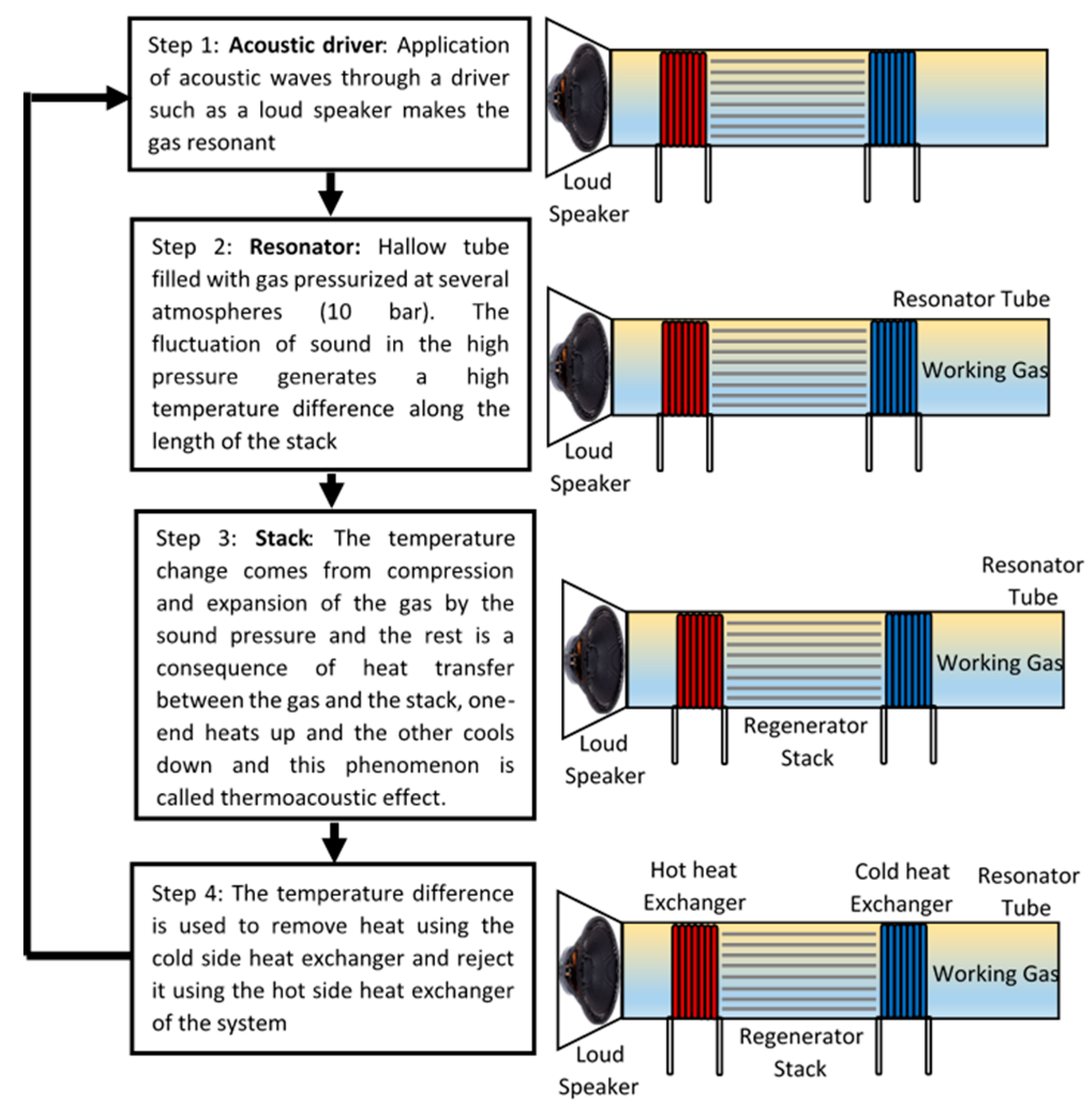
The first time a theoretical study of thermoacoustic was carried out by Kramers in 1949 by generalising the Kirchhoff theory of the attenuation of sounds waves. Thermoacoustic refrigerator has two main parts (driver and resonator), the driver houses the loudspeaker, and the resonator houses the gas, which is the medium in which the sound waves travel. The resonator houses two vital parts which are the stack and the cold and hot heat exchangers.
Thermoacoustic refrigerator (TAR) works on the principle of generating high amplitude sound waves (by the driver) in the resonator, which is a hollow tube filled with gas pressurised at several atmospheres (10 bar). The fluctuation of sound in the high pressure generates a high-temperature difference, which occurs across a stack of plates that are in between the two heat exchangers. The heat starts to flow from one side of the stack to the other, and as a consequence, one end heats up, and the other cools down, and this phenomenon is called the thermoacoustic effect. The thermoacoustic effect is mainly based on Gay-Lussac’s pressure-temperature law which states “The pressure of a given amount of gas held at a constant volume is directly proportional to the Kelvin temperature” [37]. Below Figure 4 explains the basic working principle of thermoacoustic refrigeration.
5.2. Working Materials
Thermoacoustic refrigerator does not have specific materials except those of the components of the device. The stack, for instance, needs to be made of a low thermal conductivity material, because if otherwise, the performance of the stack will be affected. Many other factors affect the stack’s performance, such as the spacing and the geometry [38]. The thermoacoustic refrigerator also requires a medium in which the sound travels to generate the cooling and heating, this medium needs to be an inert gas such as helium, helium-argon, helium-xenon, and helium-krypton, and they don’t contain any toxic or injurious substances.
5.3. Challenges and State of Development
There have been many efforts in researching thermoacoustic refrigeration in order to develop an efficient Thermo Acoustic Refrigerator (TAR). Nathad et al. designed and fabricated a TAR prototype (where helium pressurised at 1 bar was used as a medium gas) and tested it, and a temperature difference of 3 K was recorded in a one-hour test. The hot heat exchanger’s temperature rose 0.06 °C every 1.5 min, while the temperature of the cold heat exchanger rose 0.06 °C every 10 min. The output of the experiments was not satisfying to the authors as they designed the system to have a temperature difference of 30 °C. This massive drop in the output was highly likely because of helium leakage, but it was difficult to test that as the gas was pressurised at atmospheric pressure. Nathad et al. concluded that to get a higher temperature difference, the following needs to be accounted for: (1) The stack holder should not be thick as this affects the heat transfer rate. (2) The loudspeaker used in the driver needs to be of a higher power. (3) The shape of the speaker has a significant effect, as if it does not fit properly into the tube, it might cause gas leakage and power loss which diminishes the Thermoacoustic effect [39].
Saechan et al. described delta modelling and fabricated a laboratory demonstrator which achieved a minimum temperature of −8.3 °C at a storage condition of +8 °C at a 7 W cooling power. Saechan et al. studied eight different locations for the cooler along the resonator at different frequencies (58.6 and 70.3 Hz) and found that the optimum cooler’s location is at 2.52 m away from the generator [40]. In this respect, Mishra et al. after conducting experiments for high-temperature gradient, concluded that the best location for the stack was 1 cm from the top and it was also found, by hit and trial, that the optimum frequency is 369 Hz [41]. Saechan et al. concluded that, to achieve higher cooling load, future research should include instance tuning of the acoustic network, which will result in reducing the phase difference between the regenerator and the volumetric velocity [40].
Wang et al. wanted to benefit from the wasted heat produced by the heavy-duty vehicles engines to cool down the cab and the sleeper; therefore they proposed and simulated heat-driven thermoacoustic refrigerators and analysed the simulation results. The concept of the idea is that the cooling power is secured by harnessing the acoustic work produced by the engine. The results showed that a cooling power of 3.1 kW could be obtained at a COP of 0.41 [42]. Xu et al. have done a similar study to what Wang’s group did. Xu et al. have studied a thermoacoustically driven refrigerator for low-grade heat recovery using gas-liquid resonator. The study has considered the liquid volume ratio and the mean pressure, and the results have shown that a cooling power of 2.7 kW can be achieved with a system’s efficiency of 67% when increasing the pressure; as the overall performance is determined by high amplitude wave pressure and low working frequency [43].
Wang et al. have investigated and have numerically studied multi-stage travelling wave thermoacoustic refrigerator using SAGE software and have compared the results to a single-stage refrigerator. The results have shown that the cooling power of a single stage of 2.17 kW has increased to 6.42 kW achieving an increment of 195% for a seven stage refrigerator, and the COP increased from 2.60 to 3.19 [44]. Thermoacoustic technology has seen some noticeable progress in recent years as better cooling loads were achieved. This technology may find a market within certain fields as vehicle cooling for the technology can benefit from acoustic work produced by vehicles engines.
5.4. Applications
Thermoacoustic technology is not yet fully developed, and its efficiency in its present development state is lower than that of the vapour compression system. There is not a system working on Thermoacoustic principle commercially available yet. Thermoacoustic refrigeration, when fully researched and developed, can have the potential of covering a wide range of applications from cryogenic temperatures to food applications and domestic appliances.
There is room for development in structural design as well as enhancing heat transfer within the stack and between the heat exchangers and the stack. Also, different gases at different pressures need to be studied, e.g., nitrogen, argon, and different gas mixtures, such as helium-argon, helium-krypton, and helium-xenon.
5.5. Advantages and Disadvantages
Thermoacoustic refrigerator has no moving parts, and it is considered reliable, simple and run at a very low cost. This technology can also be operated by converting waste heat into sound waves. Thermoacoustic technology is still under research, and currently, it has minimal efficiencies as well as small temperature spans.
6. Stirling Refrigeration
6.1. Basic Working Principles
The Stirling cycle is one of the most famous thermodynamics cycles, and it can be implemented as a refrigerator, heat pump, and an engine. There are three types of Stirling engines:
- Alpha engine: this type has two power pistons, and that makes it heavier than the other two types (beta and gamma). Both pistons are connected to a crankshaft, where the hot and cold pistons are 90 degrees apart, the crankshaft moves in and out within two cylinders. The alpha engine works on the following principle:
- Expansion: The gas heats up and expands and drives both pistons in the crankshaft.
- Transfer: Then the momentum of the flywheel carries the engine through the next 90 degrees, this causes most of the air to be transferred over to the cold cylinder.
- Contraction: The majority of the expanded gas shifts over to the cold cylinder, it cools and contracts which sucks both pistons outwards, away from the crankshaft.
- Transfer: The same transfer operation is repeated to transfer the air to the hot cylinder and thus complete the cycle.
- Beta engine: this type has one cylinder, one piston and a displacer which shuttles the air back and forth with the cylinder. When the displacer moves away from the hot side, it forces the air to go to the cold side, and thus the air heats up, expands, and the piston gets pushed outwards. Reversely, when the displacer moves towards the hot end, it causes the air to go to the cold side and cools down, contracts and the piston gets sucked inwards. In beta engine, the displacer and the piston are 90° apart.
- Gamma (low-temperature differential): Gamma engine works by using the temperature difference between two metal plates, and this particular engine is complex as it has many components. Gamma engine is composed of two plates (bottom & top or hot & cold), displacer (contains a displacer cylinder and a rod), flywheel and a power piston with its supporting rod.
This engine works when the displacer moves up and down, causing the air within the cylinder to be in contact with either the hot or the cold plate. When the air is in contact with the hot plate, the air heats up, increases in volume and forces the power piston upwards. Similarly, when the air is in contact with the cold plate, it cools, contracts in volume and creates a partial vacuum within the cylinder, the higher atmospheric pressure outside forces the power piston down in its cylinder. When the power piston is made to move by the changing pressures, it transfers this force through its connecting rod to the flywheel. This, in turn, forces the displacer rod to move as it is connected to the flywheel through the crankshaft, and so the cycle can continue. The power piston must always be 90° behind the displacer on the crankshaft, and this allows the air inside the displacer cylinder to either expand or contract. Below Figure 5 depicts the basic working principle of the technology.
6.2. Working Materials
Stirling engines do not have specific materials other than the components mentioned in each one of the three types. However, Stirling engines use air, helium, nitrogen and hydrogen as their working fluids, and all these gases are inert, and they do no harm to the environment.
6.3. Challenges and State of Development
The main barrier and challenge that hinders the commercialising of this technology in its present state is the fact that it has low cooling/heating capacities as well as a low efficiency when compared to vapour compression systems. However, besides the direct use of the Stirling engine in cooling and heating, it can also be used to improve the performance of other technologies. Gao et al. studied a hybrid refrigerator which combines magnetic refrigeration effect with Stirling cycle effect at room temperature. This hybrid refrigerator was built using sheets of Gadolinium (Gd) as the regenerator, and a rotating Halbach permanent magnet which secured of magnetic field (0 to 1.4 T), all these components were placed in a helium-gas (heat transfer fluid) filled alpha type Stirling engine. The hybrid system achieved a cooling power of 40.3 W and 56.4 W over-temperature difference of 15 K and 12 K, respectively. Gao et al. concluded that the performance of the hybrid system improved by 28% when compared to the performance of a stand-alone Stirling cycle [45].
Ahmad et al. used COMSOL to develop a small-scale alpha Stirling Cryocooler and investigated the factors that affect the performance, such as operating speed, phase angle and heat exchanger length. The results showed that the best performance could be achieved with a phase angle of 90° and a heat exchanger length of 142 mm, and they also concluded that further length hinders the heat transfer. The Cryocooler achieved a cooling power of 455 W at a heat sink of 193 K with a COP of 0.57 [46]. Hachem et al. modelled an air-filled beta type Stirling refrigerator in terms of operations and geometrical parameters. The model was validated by experiments, and the results showed that the maximum COP could be achieved at a certain speed which is totally different to the speed at which the maximum cooling capacity could be achieved; which makes achieving maximum COP comes at the expense of attaining maximum cooling capacity and vice versa. The results also showed that the cold temperatures are reached by increasing the swept volume of the cold chamber. Hachem et al. concluded that the losses are in direct relation with the dimension of the engine and the optimal dimensions are a diameter of 22 mm and a length of 60 mm [47].
Gadalkareem et al. proposed a design for a hot and cold water dispenser where the heat rejected by the engine was used to secure the hot water. Gadalkareem et al. developed a mathematical model and evaluated the device’s performance, and the results showed the Stirling cycle has a high potential in water coolers as a cold temperature of 10 °C and hot of 95 °C could be achieved. It was also proven that the cycle consumes the least electric power when used in water dispensers [48].
6.4. Applications
Stirling refrigerators proved themselves successful in many applications, and that is due to their high reliability in terms of fast cool-down as well as their lightweight and low power consumption. Since Stirling refrigerators can achieve low temperatures, the demand for their use in Cryocoolers massively increased. Therefore, Stirling refrigerators are very efficient for water dispensers as well as they can be used in food applications such as small portable refrigerators and freezers, and in beverage vending machines. The literature showed no attempt of a large-scale cooling/heating device based on Stirling cycles.
6.5. Advantages and Disadvantages
Stirling engines, when used in refrigeration, are reliable and have a quick response in terms of cooling and heating as well as they are light in weight, which makes them ideal for small portable applications. On the other hand, Stirling refrigeration so far has very low capacities and need more research before it could be commercially available for bigger scales. The system also has moving parts which means more maintenance will be required and therefore a higher running cost.
7. Barocaloric Refrigeration
7.1. Basic Working Principles
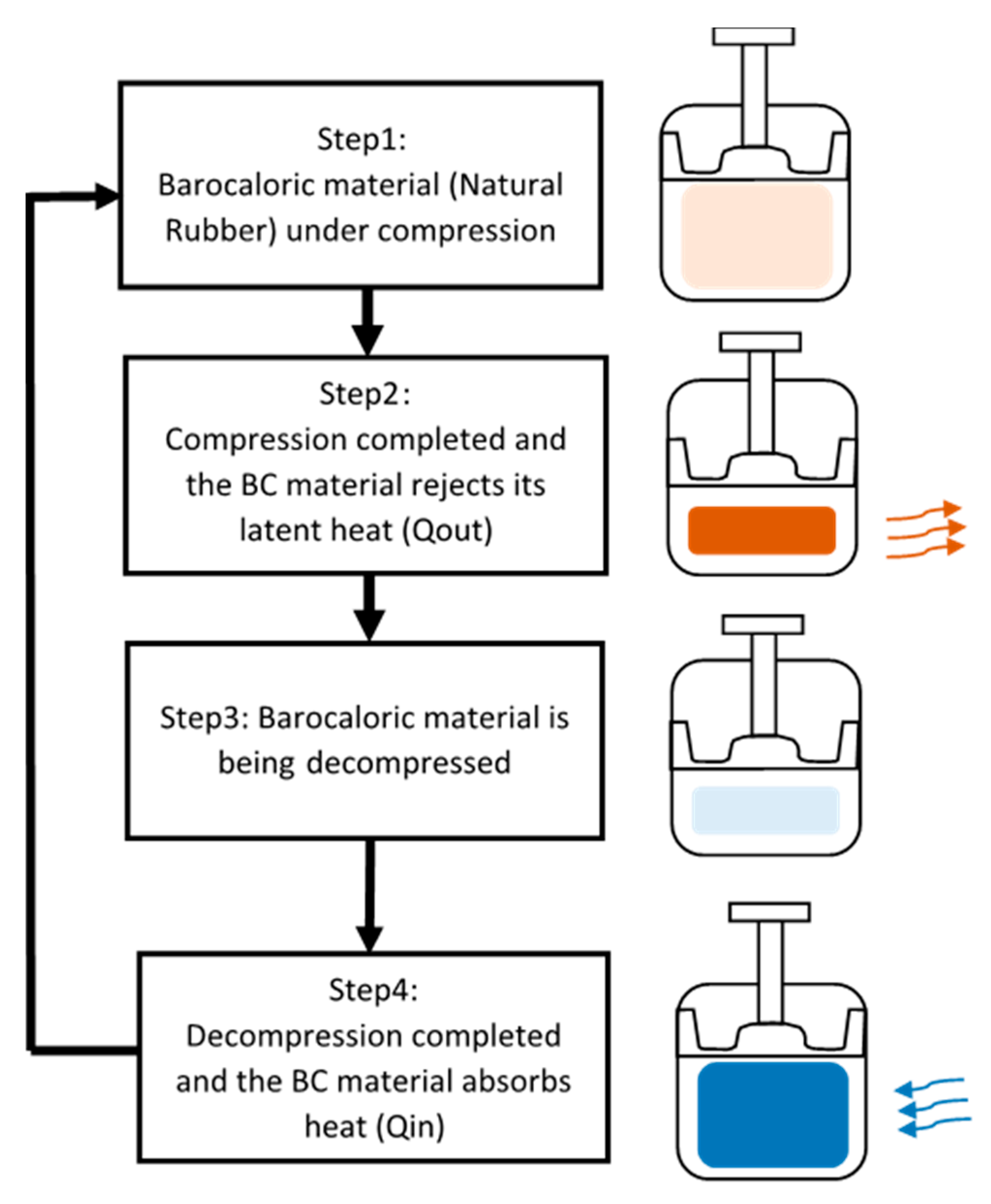
The Barocaloric refrigeration cycle has four main processes: adiabatic compression where the Barocaloric material gets compressed and the second process is heat transfer from the cold to the hot heat exchanger, the third process is the decompression which is followed by the fourth process where the heat transfers from the hot to the cold heat exchanger. The Barocaloric cooling is also known as active Barocaloric regenerative refrigeration cycle (ABR). The ABR has four main cycles which are: adiabatic compression, heat transfers from the cold heat exchanger (CHEX) to the hot heat exchanger (HHEX), adiabatic decompression, and heat transfers from HHEX to CHEX. Figure 6 explains the basic working principle of the technology.
7.2. Working Materials
The main Barocaloric materials used in ABR are natural rubber and elastomers materials as they exhibit giant Barocaloric effect (BCE). The Barocaloric effect occurs when a Barocaloric material is put under pressure and therefore, the material response by expelling and absorbing heat as a result of the pressure. The most commonly used heat transfer fluids in Barocaloric refrigeration are water and water-glycol mix as well as Nano-fluids.
7.3. Challenges and State of Development
Natural rubber heats up under stress and cools down when the stress is removed. This particular property is called Barocaloric effect, and it was noticed for the first time by John Gough in 1805. Bom et al. studied the giant Barocaloric effect in natural rubber, which has higher entropy and temperature difference among its counterparts. Bom et al. through experiments found that a temperature difference of 25 K can be achieved at a stress of 390 MPa at 314 K; the results also showed that a change in entropy () of 96 J/kg K can be achieved at a stress of 173 MPa at 290 K [49].
Aprea et al. investigated, via a two-dimensional model 2D, the effect on heat transfer in an ABR using vulcanising rubber as core material and Nanofluid (ethylene glycol-water) as the working fluid. Vulcanised rubber is a treated rubber with sulfur and heat to exhibit high strength, elasticity and durability. Aprea et al. studied the heat transfer between the ABR and the working fluid by varying the concentration of the fluid as well as adding Copper (Cu) to the mixture. The results showed that adding 10% Cu to the mixture enhances the heat transfer by 30% [50].
7.4. Application
The literature on Barocaloric technology is very minimal, and there are no comprehensive studies and review nor experimental results, as it is still in the early stage of research.
8. Elastocaloric Refrigeration
8.1. Basic Working Principles
Elastocaloric refrigeration works on a similar principle as Barocaloric refrigeration which is exposing the Elastocaloric materials (ECM) to pressure; this pressure could be applied by means of compression, tension, bending or torsion. Elastocaloric has two phases, Austenite and Martensite, and each phase has two activation temperatures at which each phase starts and finishes (Austenite start, Austenite finish, Martensite start, & Martensite finish). Each activation temperature happens at specific stress, depending on the material properties, as follows:
: Stress at which the Martensite phase is activated
: Stress at which the Martensite phase ends
: Stress at which the Austenite phase is activated
: Stress at which Austenite phase ends
The material starts rejecting heat when the martensite state is activated, and at the material rejects all its latent heat, and the material starts absorbing heat from the surrounding at . Below Figure 7 depicts the basic principle of the technology.
8.2. Working Materials
The main Elastocaloric Material ECM is called Shape Memory Alloys (SMA). There are many different SMA materials and the most common material for heating and cooling applications is a blend of Nickel (Ni), and Titanium (Ti) and this particular blend (NiTi) is also named NiTiNOL in honour of its discovery at the Naval Ordnance Laboratory (NOL). NiTi is the most used blend in heating and cooling applications for its superior biocompatibility and fatigue behaviour, as well as its high-temperature span and high entropy change. However, NiTi can be alloyed with many different chemical elements like Copper (Cu), Ferrum (Fe), Rhodium (Rh), Palladium (Pd), Cobalt (Co), and Gallium (Ga), and each blend has different properties with respect to adiabatic temperature, hysteresis and fatigue life. For instance, when NiTi is doped with Cu, the blend will have a temperature difference of around 10 K as well as its fatigue life significantly enhances, thus it can withstand millions of cycles; but on the other hand, copper reduces the latent heat. There are two other groups of shape memory alloys, which are Cu-based alloys and Fe-based alloys. Cu-based blends like CuZnAl and CuAlNi have smaller hysteresis, which means less energy dissipation; however, they require less stresses to fully transform from one phase to another [52].
Since different blends have different properties, therefore the loading strategy decides which blend is better for the application in question. There are four main loading methods, which are compression, tension, bending and torsion. In compression, we find that the Elastocaloric effect is sustained for a longer time and the potential for defects and cracks to grow and propagate is limited, which means a better fatigue life. On the other hand, we find that loading in tension provides a rapid heat transfer and a higher temperature difference for smaller stress. However, the Electrocaloric effect deteriorates in tension. Bending can be likened to compression, as the loading happens in the inner part of the bent piece, while the loading in tension occurs in the outer part. In bending mode, the stress-induced phase transformation remains incomplete due to the resulting strain profiles and the neutral axis. There’s no literature on using torsion for heating/cooling applications.
8.3. Challenges and State of Development
The literature revealed very limited research on this topic. Most of the literature is at the level of the material and not the application of the material in heating and cooling systems. The implementation and usage of SMA for cooling and heating are discussed below:
Qian Suxin carried out experimental research on SMA thermoelastic cooling system and evaluated the performance potential and limitations of this emerging new technology. A prototype was designed and fabricated at a maximum cooling capacity of 100 W, of which 65 W was achieved at a maximum temperature lift of 4.2 K. Qian’s design was based on Nitinol tubes arranged in a hexagonal layout in two conjugated beds under compression. Qian claimed that NiTi tube’s thermal mass does not allow heat transfer with high frequency, and that might be a limitation to increase the cycle’s frequency. To solve this issue, Qian used a thinner wall with smaller thermal mass per NiTi tube, and inserted plastic tubes inside the loading plate and the loading metal and that is to reduce the heat transfer between the heat transfer fluid (HTF) and the metal surfaces [53].
Qian did not look at properties losses, adiabatic compression losses and mechanical losses of the material. Qian only looked at minimising heat transfer loss and cyclic loss and found that the cyclic losses are caused by the dead thermal masses (masses of the material used to support the tubes and to apply the loading, and those masses do not contribute in the efficiency of the system, in contrast, they reduce it) inside the system as the dead thermal mass of Heat Transfer Fluid (HTF) neutralises the heat generated by the thin NiTi tubes and this case is exacerbated with high frequencies. Therefore, the performance of the system is limited by the parasitic loss caused by HTF heat dissipation, conduction to dead thermal mass and metal parts. Qian also concluded that the material level irreversibility causes performance degradation, which accounts to around more than 40% efficiency loss. Qian also observed that thermoelastic cooling works better in small to medium temperature lift applications [53].
Hinnerk Ossmer was the second person to conduct research on the feasibility of using SMA to produce micro-cooling. The main two objectives for Ossmer’s work were identifying suitable materials for elastocaloric micro-cooling after profoundly understanding their thermo-mechanical behaviours, as well as investigating the engineering tasks that would allow actual heat pumping for miniature scales. Ossmer explained the procedure of manufacturing different SMA blends and different ways of testing their properties such as differential scanning calorimetry, tensile test, infrared thermography and digital image correlation. Ossmer also investigated different SMA geometries (films and foils) under different ways of loading (tensile, compression and bending) for elastocaloric micro-cooling. Ossmer found that the NiTi-based foils and films have the highest temperature changes as their self-cooling can get to −15 K and they could achieve a maximum temperature lift of 14 K and a COP of 6.7 for a temperature span of 6.3 K [54].
Ossmer also found that thin SMA samples provide better cooling and heat pumping on a small scale, as they allow better heat transfer due to their large surface-to-volume ratio. Ossmer also stated that the highest COP is obtained for NiTiCuCo films as they have a low hysteresis comparing to their counterparts, whereas NiTi samples showed a strong functional degradation [54].
Ossmer run some experiments on a demonstrator built using NiTiFe foil bridges and the sink/source were fabricated from several copper segments. The experiments showed that decreasing the masses of sink and source did not result in increasing the temperature lift, which represents a challenge for small-scale applications [54].
Kirsch et al. designed an SMA based air conditioning system. They used swash plates to convert rotary movement into linear movement as well as an inclination angle which allows loading (tensile) and adjusting the SMA strain during the rotation. This design allows using a larger amount of SMA in a smaller assembly space. Through investigations, Kirsch et al. found that a combination of an adiabatic and an isothermal cycle shows the best performance. In this work, Kirsch et al. presented the concept of a continuously operating air cooling device without having mentioned any information about COP and temperature lift [55].
Qian et al. proposed a heat-driven elastocaloric cycle using a high-temperature SMA. They built a 32 NiTi SMA wires with 1 mm diameter and divided the wires into four bundles; each bundle contains eight wires. This system showed a temperature difference of 26 K under no load, and it produced 0.64 W/g but under zero temperature difference. They also found that the prototype can be driven by a temperature below 80 °C [53].
Besides the studies mentioned above, many other studies on the implementation of SMA in cooling/heating systems were carried out without success in scaling up the output of the systems in question. In 2016, the Technical University of Denmark collaborated with the University of Ljubljana in an SMA device project, and they achieved a temperature span of 15.3 K at a COP of 3.5. The attempts continued, and Engelbrecht et al. designed an SMA device using 10 NiTi plates under tension, and they achieved a temperature span of 19.9 K and a heating power of 800 W per kg. Their device failed before completing 6000 of active elastocaloric regenerator (AER) cycles, which makes it impossible for the device to be commercialised. Kirsch et al. worked on a cooling device using NiTiCo-based alloys, and they achieved a cooling power of 250 W with a temperature span of 10 K and a COP of 9.5. Researchers at the University of Saarland in collaboration with Karlsruhe Institute of Technology designed a single-stage cooling/heat-pumping device using NiTi sheets under tension, and their device achieved a temperature span of 7 K [56]. There have also been attempts to achieve microscale cooling devices; the last attempt was carried out by Bruederkin et al. where they presented a microscale system that achieved a temperature span of 14.8 K [57].
The literature showed that all the so far designed and manufactured prototypes either work under tension or tubes under compression. The experiments also showed that deciding tension for a heat pump device is not practical despite its excellent heat transfer potential, as the material under tension tends to break a lot quicker, and the reason for that is that the cracks on the surface of the material grow and propagate, and that leads to the failure of the material. On the other hand, compressive loading has a longer fatigue life, as the cracks and impurities don’t grow and propagate. However, compressive loading requires particular geometries to avoid problems such as buckling. The literature showed that in one of the attempts, compression was used as the loading strategy for NiTi tubes, and in that particular project, the designer used plastic supports to restrain buckling, and that compromised the heat produced as well as the heat transfer, and subsequently the performance of the device. Therefore, if compressive loading were to be considered for an SMA heat-pump, special attention should be paid for the geometry, putting into consideration the effectiveness of the heat-transfer between the material and the heat transfer fluid.
8.4. Application
Elastocaloric refrigeration can cover a broad spectrum of applications thanks to the ability of adjusting the Austenite and Martensite activation temperatures. This technology can be used in domestic cooling and heating devices, large heat pumps for large scale cooling and heating as well as in heating and cooling vehicles.
8.5. Advantages and Disadvantages
This technology has been researched in different institutions and research groups in the last five years; and it is considered one of the most promising alternatives for vapour compression system, and that is because it doesn’t have the problems its counterparts have. The other emerging technologies either depend on toxic materials, incredibly expensive materials or have low efficiencies. Moreover, we find that Elastocaloric technology:
- is scalable;
- its core material is completely environmentally friendly, cheap, and abundant;
- and it has a high efficiency and high COPs.
On the other hand, this technology is relatively new and still needs more research before it could be commercially available. Below Table 1 is a summary for the seven technologies reviewed in this paper.
9. Conclusions
Emerging alternative technologies are expected to play an important role in the transition into environmentally friendly cooling and heating systems. Many alternative systems have been and are still being researched intensively by different research groups in different countries. None of the seven technologies which have been critically evaluated in this paper has been commercialized yet. The literature showed that the Magnetocaloric technology has a long way to go as the materials are still unavailable globally, and when found, they will need to be studied thoroughly from different perspectives, especially materials aging, as this decides the life span of the Magnetocaloric device. Similarly, Electrocaloric technology has its materials challenge as the lead-based materials are toxic and detrimental to human’s lives. Therefore, more research into lead-free materials is needed for this technology to compete. On the other hand, thermoelectric and thermoacoustic technologies have not yet achieved satisfactory efficiencies and COPs, and they are, so far, confined in small applications and for research purposes. There are two other technologies that work on the same principle which are Barocaloric and Elastocaloric; the chances for Barocaloric to progress are very limited due to the short fatigue life of natural rubber which is the core material of the technology. Whereas Elastocaloric is the most promising technology among its alternative counterpart technologies, and that is for the abundance of its core material as well as the scalability. Elastocaloric technology, when fully developed, can cover a wide spectrum of heating/cooling loads from a few kilowatts to a few hundreds of kilowatts.
Author Contributions
All authors have contributed equally in the methodology, investigation, data curation, writing—original draft preparation, writing—review and editing. All authors have read and agreed to the published version of the manuscript.
Funding
This research received no external funding.
Conflicts of Interest
The authors declare no conflict of interest.
References
- Ožbolt, M.; Kitanovski, A.; Tušek, J.; Poredoš, A. Electrocaloric vs. magnetocaloric energy conversion. Int. J. Refrig. 2014, 37, 16–27. [Google Scholar] [CrossRef]
- Tassou, S.A.; Lewis, J.; Ge, Y.; Hadawey, A.; Chaer, I. A review of emerging technologies for food refrigeration applications. Appl. Therm. Eng. 2010, 30, 263–276. [Google Scholar] [CrossRef] [Green Version]
- Franco, V.; Blázquez, J.; Ipus, J.; Law, J.; Moreno-Ramírez, L.; Conde, A. Magnetocaloric effect: From materials research to refrigeration devices. Prog. Mater. Sci. 2018, 93, 112–232. [Google Scholar] [CrossRef]
- Aprea, C.; Greco, A.; Maiorino, A. Magnetic refrigeration: A promising new technology for energy saving. Int. J. Ambient. Energy 2014, 37, 294–313. [Google Scholar] [CrossRef] [Green Version]
- Eriksed, D. Active Magnetic Regenerator Refrigeration with Rotary Multi-Bed Technology. Ph.D. Thesis, Technical University of Denmark, Lyngby, Denmark, 2016. [Google Scholar]
- Olsen, U.L.; Bahl, C.R.; Engelbrecht, K.; Nielsen, K.K.; Tasaki, Y.; Takahashi, H. Modeling of in-vehicle magnetic refrigeration. Int. J. Refrig. 2014, 37, 194–200. [Google Scholar] [CrossRef] [Green Version]
- Gatti, J.; Muller, C.; Vasile, C.; Brumpter, G.; Haegel, P.; Lorkin, T. Magnetic heat pumps–Configurable hydraulic distribution for a magnetic cooling system. Int. J. Refrig. 2014, 37, 165–175. [Google Scholar] [CrossRef]
- Govindaraju, V.; Vilathgamuwa, D.M.; Ramanujan, R. Modelling of a magnetocaloric system for cooling in the kilowatt range. Int. J. Refrig. 2014, 43, 143–153. [Google Scholar] [CrossRef]
- Albertini, F.; Bennati, C.; Bianchi, M.; Branchini, L.; Cugini, F.; De Pascale, A.; Fabbrici, S.; Melino, F.; Ottaviano, S.; Peretto, A.; et al. Preliminary Investigation on a Rotary Magnetocaloric Refrigerator Prototype. Energy Procedia 2017, 142, 1288–1293. [Google Scholar] [CrossRef]
- Li, Z.; Shen, J.; Li, K.; Gao, X.; Guo, X.; Dai, W. Assessment of three different gadolinium-based regenerators in a rotary-type magnetic refrigerator. Appl. Therm. Eng. 2019, 153, 159–167. [Google Scholar] [CrossRef]
- Huang, B.; Lai, J.; Zeng, D.; Zheng, Z.; Harrison, B.; Oort, A.; Van Dijk, N.; Brück, E. Development of an experimental rotary magnetic refrigerator prototype. Int. J. Refrig. 2019, 104, 42–50. [Google Scholar] [CrossRef]
- He, J.; Wu, J.; Lu, B.; Liu, C. Comparative study on the series, parallel and cascade cycles of a multi-mode room temperature magnetic refrigeration system. Int. J. Refrig. 2020, 117, 94–103. [Google Scholar] [CrossRef]
- Kutjak, Z.; Rozic, B.; Pirc, R. Electrocaloric Effect: Theory, Measurements, and Applications; Wiley: Hoboken, NJ, USA, 2015. [Google Scholar]
- Mischenko, A. Giant Electrocaloric Effect in Thin-Film PbZr0.95Ti0.05O3. Science 2006, 311, 1270–1271. [Google Scholar] [CrossRef] [PubMed] [Green Version]
- Crossley, S. Electrocaloric Materials and Devices. Ph.D. Thesis, University of Cambridge, Cambridge, UK, 2013. [Google Scholar]
- Echa.europa.eu. Lead-Substance Information-ECHA. 2019. Available online: https://echa.europa.eu/substance-information/-/substanceinfo/100.028.273 (accessed on 19 December 2019).
- Zaitouni, H.; Hajji, L.; Mezzane, D.; Choukri, E.; Alimoussa, A.; Ben Moumen, S.; Rožič, B.; El Marssi, M.; Kutnjak, Z. Direct electrocaloric, structural, dielectric, and electric properties of lead-free ferroelectric material Ba0.9Sr0.1Ti1−xSnxO3 synthesized by semi-wet method. Phys. B Condens. Matter 2019, 566, 55–62. [Google Scholar] [CrossRef] [Green Version]
- Abomostafa, H.; Ellamey, M. Studying the mechanical properties of Barium Strontium Titanate ceramics by an ultrasonic pulse-echo technology. J. Ovonic Res. 2018, 14, 307–316. [Google Scholar]
- Aprea, C.; Greco, A.; Maiorino, A.; Masselli, C. A comparison between different materials in an active electrocaloric regenerative cycle with a 2D numerical model. Int. J. Refrig. 2016, 69, 369–382. [Google Scholar] [CrossRef]
- Molin, C.; Peräntie, J.; Le Goupil, F.; Weyland, F.; Sanlialp, M.; Stingelin, N.; Novak, N.; Lupascu, D.C.; Gebhardt, S.E. Comparison of direct electrocaloric characterization methods exemplified by 0.92 Pb(Mg1/3 Nb2/3 )O3-0.08 PbTiO3 multilayer ceramics. J. Am. Ceram. Soc. 2017, 100, 2885–2892. [Google Scholar] [CrossRef]
- Aprea, C.; Greco, A.; Maiorino, A.; Masselli, C. Electrocaloric refrigeration: An innovative, emerging, eco-friendly refrigeration technique. J. Phys. Conf. Ser. 2017, 796, 12019. [Google Scholar] [CrossRef]
- Shi, J.; Zhu, R.; Liu, X.; Bi-Jun, F.; Yuan, N.; Ren, Y.; Luo, H. Large Electrocaloric Effect in Lead-Free (Ba0.85Ca0.15)(Zr0.1Ti0.9)O3 Ceramics Prepared via Citrate Route. Materials 2017, 10, 1093. [Google Scholar] [CrossRef]
- Aprea, C.; Greco, A.; Maiorino, A.; Masselli, C. Solid-state refrigeration: A comparison of the energy performances of caloric materials operating in an active caloric regenerator. Energy 2018, 165, 439–455. [Google Scholar] [CrossRef]
- Lu, S.; Li, J.; Cheng, M.; Li, Q.; Li, F.; Lv, Z.; Zhang, Y.; Lu, C.; Li, S. Joule heating-A significant factor in electrocaloric effect. Ceram. Int. 2019, 45, 16992–16998. [Google Scholar] [CrossRef]
- Guvenc, C.M.; Adem, U. Influence of aging on electrocaloric effect in Li+ doped BaTiO3 ceramics. J. Alloy. Compd. 2019, 791, 674–680. [Google Scholar] [CrossRef]
- Plaznik, U.; Vrabelj, M.; Kutnjak, Z.; Malič, B.; Rožič, B.; Poredoš, A.; Kitanovski, A. Numerical modelling and experimental validation of a regenerative electrocaloric cooler. Int. J. Refrig. 2019, 98, 139–149. [Google Scholar] [CrossRef]
- Shi, J.; Han, D.; Li, Z.; Yang, L.; Lu, S.-G.; Zhong, Z.; Chen, J.; Zhang, Q.; Qian, X. Electrocaloric Cooling Materials and Devices for Zero-Global-Warming-Potential, High-Efficiency Refrigeration. Joule 2019, 3, 1200–1225. [Google Scholar] [CrossRef]
- Zhao, D.; Tan, G. A review of thermoelectric cooling: Materials, modeling and applications. Appl. Therm. Eng. 2014, 66, 15–24. [Google Scholar] [CrossRef]
- Navarro-Peris, E.; Corberan, J.M.; Ancik, Z. Evaluation of the potential recovery of compressor heat losses to enhance the efficiency of refrigeration systems by means of thermoelectric generation. Appl. Therm. Eng. 2015, 89, 755–762. [Google Scholar] [CrossRef]
- Pietrzyk, K.; Ohara, B.; Watson, T.; Gee, M.; Avalos, D.; Lee, H. Thermoelectric module design strategy for solid-state refrigeration. Energy 2016, 114, 823–832. [Google Scholar] [CrossRef]
- Cao, L.; Han, J.; Duan, L.; Huo, C. Design and Experiment Study of a New Thermoelectric Cooling Helmet. Procedia Eng. 2017, 205, 1426–1432. [Google Scholar] [CrossRef]
- Xu, W.; Liu, Y.; Marcelli, A.; Shang, P.; Liu, W. The complexity of thermoelectric materials: Why we need powerful and brilliant synchrotron radiation sources? Mater. Today Phys. 2018, 6, 68–82. [Google Scholar] [CrossRef]
- Moria, H.; Ahmed, M.; Alghanmi, A.; Mohamad, T.I.; Yaakob, Y. Experimental Study of Solar Based Refrigerator Using Thermoelectric Effect. Energy Procedia 2019, 158, 198–203. [Google Scholar] [CrossRef]
- Tian, X.-X.; Asaadi, S.; Moria, H.; Kaood, A.; Pourhedayat, S.; Jermsittiparsert, K. Proposing tube-bundle arrangement of tubular thermoelectric module as a novel air cooler. Energy 2020, 208, 118428. [Google Scholar] [CrossRef]
- Shen, L.; Zhang, W.; Liu, G.; Tu, Z.; Lu, Q.; Chen, H.; Huang, Q. Performance enhancement investigation of the thermoelectric cooler with segmented configuration. Appl. Therm. Eng. 2020, 168, 114852. [Google Scholar] [CrossRef]
- Cuce, E.; Guclu, T.; Cuce, P.M. Improving thermal performance of thermoelectric coolers (TECs) through a nanofluid driven water to air heat exchanger design: An experimental research. Energy Convers. Manag. 2020, 214, 112893. [Google Scholar] [CrossRef]
- Verma, S.S. Thermo-acoustic refrigeration. IOSR J. Mech. Civil Eng. 2014. [Google Scholar]
- Bhansali, P.S.; Patunkar, P.P.; Gorade, S.V.; Adhav, S.S.; Botre, S.S. An Overview Of Stack Design For A Thermoacoustic Refrigerator. Int. J. Res. Eng. Technol. 2015, 4, 68–72. [Google Scholar]
- Nathad, A.; Ahmed, F.; Khalid, M.O.; Kumar, R.; Hafeez, H. Experimental Analysis of an Economical Lab Demonstration Prototype of a Thermo Acoustic Refrigerator (TAR). Energy Procedia 2018, 157, 343–354. [Google Scholar] [CrossRef]
- Saechan, P.; Jaworski, J.A. Thermoacoustic cooler to meet medical storage needs of rural communities in developing countries. Therm. Sci. Eng. Process 2018, 7, 164–175. [Google Scholar] [CrossRef] [Green Version]
- Mishra, A.; Choudhary, A.K.; Tomar, T.; Korody, J. Thermoacoustic Refrigerator for High Temperature Gradient. MATEC Web Conf. 2018, 144, 04003. [Google Scholar] [CrossRef]
- Wang, H.; Yu, G.; Hu, J.; Wu, Z.; Hou, M.; Zhang, L.; Luo, E. A novel looped low-temperature heat-driven thermoacoustic refrigerator operating in room temperature range. Energy Procedia 2019, 158, 1653–1659. [Google Scholar] [CrossRef]
- Xu, J.; Luo, E.; Hochgreb, S. Study on a heat-driven thermoacoustic refrigerator for low-grade heat recovery. Appl. Energy 2020, 271, 115167. [Google Scholar] [CrossRef]
- Wang, X.; Wu, Z.; Zhang, L.; Hu, J.; Luo, E. Traveling-wave thermoacoustic refrigerator for room temperature application. Int. J. Refrig. 2020, 120, 90–96. [Google Scholar] [CrossRef]
- Gao, X.Q.; Shen, J.; He, X.N.; Tang, C.C.; Li, K.; Dai, W.; Li, Z.X.; Jia, J.C.; Gong, M.Q.; Wu, J.F. Improvements of a room-temperature magnetic refrigerator combined with Stirling cycle refrigeration effect. Int. J. Refrig. 2016, 67, 330–335. [Google Scholar] [CrossRef]
- Ahmed, H.; Almajri, A.K.; Mahmoud, S.; Al-Dadah, R.; Ahmad, A. CFD modelling and parametric study of small scale Alpha type Stirling Cryocooler. Energy Procedia 2017, 142, 1668–1673. [Google Scholar] [CrossRef]
- Hachem, H.; Gheith, R.; Aloui, F.; Ben Nasrallah, S. Optimisation of an air-filled Beta type Stirling refrigerator. Int. J. Refrig. 2017, 76, 296–312. [Google Scholar] [CrossRef]
- Gadelkareem, M.T.; EldeinHussin, A.; Hennes, G.M.; El-Ehwany, A.A. Stirling cycle for hot and cold drinking water dispenser. Int. J. Refrig. 2019, 99, 126–137. [Google Scholar] [CrossRef]
- Bom, N.M.; Imamura, W.; Usuda, E.O.; Paixao, L.S.; Carcalho AM, G. Giant barocaloric effects in natural rubber: A relevant step toward solid-state cooling. ASC Macro Lett. 2017, 7, 470–471. [Google Scholar] [CrossRef] [Green Version]
- Aprea, C.; Greco, A.; Maioriono, A.; Masselli, C. Enhancing the Heat Transfer in an Active Barocaloric Cooling System Using Ethylene-Glycol Based Nanofluids as Secondary Medium. Energies 2019, 12, 2902. [Google Scholar] [CrossRef] [Green Version]
- Lagoudas, D. Shape Memory Alloys; Springer: New York, NY, USA, 2011. [Google Scholar]
- Tušek, J.; Engelbrecht, K.; Pryds, N. Elastocaloric effect of a Ni-Ti plate to be applied in a regenerator-based cooling device. Sci. Technol. Built Environ. 2016, 22, 489–499. [Google Scholar] [CrossRef]
- Qian, S.; Wang, Y.; Yuan, L.; Yu, J. A heat-driven elastocaloric cooling system. Energy 2019, 182, 881–899. [Google Scholar] [CrossRef]
- Ossmer, H. Elastocaloric Microcooling. Ph.D. Thesis, Karlsruhe Institute of Technology (KIT), Karlsruhe, Germany, 2017. [Google Scholar]
- Kirsch, S.; Schmidt, M.; Welsch, F.; Michaelis, N.; Schütze, A.; Seelecke, S. Development of a shape memory-based air conditioning system. In Proceedings of the 59th Ilmenau Scientific Colloquium, Ilmenau, Germany, 11–15 September 2017. [Google Scholar]
- Kabirifar, P.; Žerovnik, A.; Ahčin, Ž.; Porenta, L.; Brojan, M.; Tušek, J. Elastocaloric Cooling: State-of-the-art and Future Challenges in Designing Regenerative Elastocaloric Devices. Stroj. Vestn. J. Mech. Eng. 2019, 65, 615–630. [Google Scholar] [CrossRef] [Green Version]
- Greco, A.; Aprea, C.; Maiorino, A.; Masselli, C. A review of the state of the art of solid-state caloric cooling processes at room-temperature before 2019. Int. J. Refrig. 2019, 106, 66–88. [Google Scholar] [CrossRef]
Figure 1.
Schematic showing the basic working principle of Magnetic Refrigeration.

Figure 2.
Schematics showing the basic working principle of Electrocaloric Refrigeration.

Figure 3.
Schematics showing the basic working principle of thermoelectric Refrigeration.

Figure 4.
Schematics showing the basic working principle of Thermoacoustic Refrigeration.

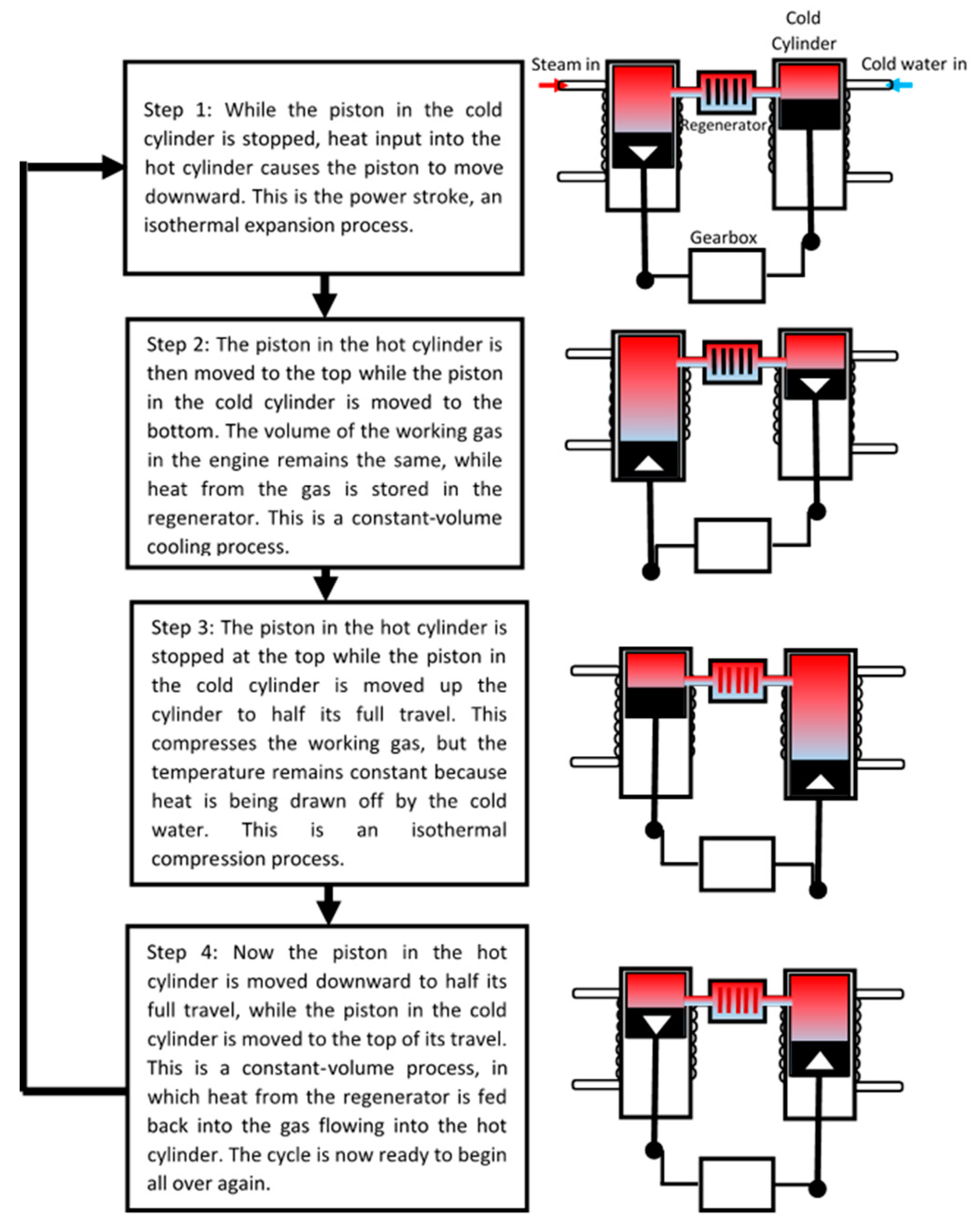
Figure 5.
Schematics showing the basic working principle of Stirling Refrigeration.

Figure 6.
Schematic showing the basic working principle of Barocaloric Refrigeration.

Figure 7.
Schematics showing the basic working principle of Elastocaloric Refrigeration based on information obtained from Shape Memory Alloys by Lagoudas [51].
Figure 7.
Schematics showing the basic working principle of Elastocaloric Refrigeration based on information obtained from Shape Memory Alloys by Lagoudas [51].


Table 1.
Characteristics and applications of emerging refrigeration technologies.
| Technology | State of Development | Barriers | Presently Available Capacity | Technical Information | Efficiency/COP of Currently Available Systems | Current/Potential Area | |||
|---|---|---|---|---|---|---|---|---|---|
| Key Material | Material’s Availability | Working Principle | Technology Readiness Levels (TRL) | ||||||
| Magnetocaloric | R&D focuses on MCM and machine design optimization | Materials are not available, and the technology can’t be used for large scale with the available current fabrication technologies | >Up to 890 W >The technology doesn’t store energy as the energy gets rejected under a specific circumstance | Rare earth magnets | 95% of the global material production is in China | Rotating magnet to expose the paramagnetic materials to a magnetic field—moving part | 3 to 4 | Highest of 9.44 at 17.8 W (1.1 kg of Gd; HTF: water) | Mobile refrigerators and cryogenic temperatures |
| Lowest of 0.7 at 0.46 W (70 g of GdEr/Gd; HTF: Helium) | |||||||||
| Electrocaloric | >R&D shifted into lead-free materials as lead is classified as a toxic substance >Manufacturing of electrocaloric material and electrodes >Compact structures that offer high electric field | To produce high EC, large electric fields and required and they cause stress in the internal structure which results in chemical degradation and electromechanical breakdown | Few watts to 2 kW | Ferroelectrics, relaxor ferroelectrics & Antiferroelectric | Lead-based material available but more research into lead-free materials are required | Electric field | 1 to 2 | 7 to 10 | Wearable coolers and heating and cooling of vehicles seats |
| Thermoelectric | Current research focuses on: >Improvement of the intrinsic efficiencies of thermoelectric materials >Optimization of cooling system’s thermal design | Thermoelectric devices have great potential energy efficiency; however, these cannot be produced economically at large scale with current fabrication technologies | Few watts | Semiconductors | Available | DC current | 4 | 0.3–0.8 | PC processors, car seats temperature control and portable food and beverage storages |
| Thermoacoustic | >Structural and mechanical design >Heat transfer within a stack and with heat exchangers> Different gases | thermoacoustic prime mover generally requires a high-temperature heat source to achieve effective acoustic power output, which is a huge barrier to utilizing the low-grade heat source | Few watts to 6.5 kW | No special material except those of the components | Available | Sound waves | 4 | up to 3.2 | cryogenic temperatures, food applications, heavy-duty vehicles and domestic appliances |
| Stirling | studies on combining Stirling cycle with other novel technologies like magnetic refrigeration to generate higher cooling performance | Manufacturing cost and the challenges of differential expansion and linear generator design is a major barrier to the introduction of Stirling-cycle heat-pumps and refrigerators, particularly when competing against the very large-scale production of vapour compression technology | Few watts to 1 kW | No special material except those of the components | Available | Mechanical movement—moving parts | 4 | <1 | Cryocoolers, water dispensers, portable refrigerators and freezers and beverages vending machines. |
| Barocaloric | Early R&D stage (materials and cycles) | Natural rubber has a very short fatigue life | Few watts on modeling | Natural Rubber | Available | Stress in tension or compression—moving parts | 4 | 6 | Miniature cryocoolers |
| Elastocaloric | Materials characterization, system engineering and stress strategies | System’s complexity and a large number of components | <1 kW | Shape Memory Alloys | Available | Stress in tension, torsion or compression—moving parts | 3 to 4 | >9 | Domestic cooling and heating devices, large heat pumps for large scale cooling and heating as well as in heating and cooling vehicles |
Publisher’s Note: MDPI stays neutral with regard to jurisdictional claims in published maps and institutional affiliations. |
© 2021 by the authors. Licensee MDPI, Basel, Switzerland. This article is an open access article distributed under the terms and conditions of the Creative Commons Attribution (CC BY) license (http://creativecommons.org/licenses/by/4.0/).
Share and Cite
MDPI and ACS Style
Ismail, M.; Yebiyo, M.; Chaer, I. A Review of Recent Advances in Emerging Alternative Heating and Cooling Technologies. Energies 2021, 14, 502. https://0-doi-org.brum.beds.ac.uk/10.3390/en14020502
AMA Style
Ismail M, Yebiyo M, Chaer I. A Review of Recent Advances in Emerging Alternative Heating and Cooling Technologies. Energies. 2021; 14(2):502. https://0-doi-org.brum.beds.ac.uk/10.3390/en14020502
Chicago/Turabian StyleIsmail, Mubarak, Metkel Yebiyo, and Issa Chaer. 2021. "A Review of Recent Advances in Emerging Alternative Heating and Cooling Technologies" Energies 14, no. 2: 502. https://0-doi-org.brum.beds.ac.uk/10.3390/en14020502
Note that from the first issue of 2016, this journal uses article numbers instead of page numbers. See further details here.