
Robotic Mapping Approach under Illumination-Variant Environments at Planetary Construction Sites

1
Department of Geoinformatic Engineering, Inha University, Incheon 22212, Korea
2
Department of Mechanical Engineering, Korea Advanced Institute of Science and Technology, College of Engineering, Daejeon 34141, Korea
3
Department of Future Technology and Convergence Research, Korea Institute of Civil Engineering and Building Technology, Goyang-si 10223, Korea
*
Author to whom correspondence should be addressed.
Remote Sens. 2022, 14(4), 1027; https://0-doi-org.brum.beds.ac.uk/10.3390/rs14041027
Submission received: 25 January 2022
/
Revised: 14 February 2022
/
Accepted: 17 February 2022
/
Published: 20 February 2022
(This article belongs to the Special Issue Planetary Geologic Mapping and Remote Sensing)
Abstract
:In planetary construction, the semiautonomous teleoperation of robots is expected to perform complex tasks for site preparation and infrastructure emplacement. A highly detailed 3D map is essential for construction planning and management. However, the planetary surface imposes mapping restrictions due to rugged and homogeneous terrains. Additionally, changes in illumination conditions cause the mapping result (or 3D point-cloud map) to have inconsistent color properties that hamper the understanding of the topographic properties of a worksite. Therefore, this paper proposes a robotic construction mapping approach robust to illumination-variant environments. The proposed approach leverages a deep learning-based low-light image enhancement (LLIE) method to improve the mapping capabilities of the visual simultaneous localization and mapping (SLAM)-based robotic mapping method. In the experiment, the robotic mapping system in the emulated planetary worksite collected terrain images during the daytime from noon to late afternoon. Two sets of point-cloud maps, which were created from original and enhanced terrain images, were examined for comparison purposes. The experiment results showed that the LLIE method in the robotic mapping method significantly enhanced the brightness, preserving the inherent colors of the original terrain images. The visibility and the overall accuracy of the point-cloud map were consequently increased.
1. Introduction
The international space community has been increasingly committed to returning humans to the Moon, leading to the establishment of a permanent base and, eventually, the Mars base (Figure 1) [1]. In situ resource utilization (ISRU) technology, which aims to produce consumables from raw materials on the surfaces of the Moon and Mars, is one of the key enablers of sustainable human exploration and habitation [2,3,4,5]. For instance, water ice, recently discovered on the Moon and Mars [6,7,8,9], is used to generate hydrogen, oxygen, water, fuel, and propellants for life support [10,11]. Regolith is another available resource to produce construction materials such as bricks and blocks [12,13]. Three-dimensional (3D) construction printing technology has been proposed as a robust and efficient means to construct planetary infrastructure under extreme environments [14,15,16,17].
Planetary construction necessitates collaborative efforts from a variety of fields, one of which is 3D terrain mapping for on-site construction planning and management. Different from Earth construction, various types of teleoperated robots are expected to build a planetary base and infrastructure [14,18,19]. A highly detailed and accurate 3D terrain map is essential for planning robotic construction operations such as site preparation and infrastructure emplacement. Although planetary remote sensing data have been used to create global terrain maps [20,21], their spatial resolutions are insufficient to support robotic construction. Rover-based 3D mapping is compulsory to understand the topographic aspect of construction candidate sites. However, due to the homogeneous and rugged planetary terrains in a global navigation satellite system (GNSS)-denied environment, the rover’s mapping capabilities are limited. Thus, recent studies have presented numerous 3D simultaneous location and mapping (SLAM) techniques that can dynamically estimate the current position and automatically build a 3D point-cloud map of surrounding environments.
Sensors mainly used in SLAM techniques include light detection and ranging (LiDAR) and cameras. LiDAR SLAM, which allows high-resolution and long-range observations, can improve the autonomous navigation of planetary rovers. Tong et al. [22] and Merali et al. [23] presented a 3D SLAM framework using rover-mounted LiDAR and demonstrated globally consistent mapping results over test areas. Shaukat et al. [24] presented camera–LiDAR fusion SLAM, in which LiDAR overcomes the camera’s field of view and point density restrictions and allows the camera to obtain a semantic interpretation of a scene. However, planetary rovers typically suffer from limited capabilities in terms of power, computational resources, and data storage [25]. Furthermore, no LiDAR exists that can be applied to contemporary planetary rovers. In this regard, visual SLAM, which mainly uses a camera system, has been considered to develop a 3D robotic mapping method for planetary surfaces. In comparison to LiDAR, the advantage of a camera system is that it is relatively lighter and consumes less power per unit. Additionally, as point clouds with color information can be generated, static and kinematic objects can be easily detected and identified in the dynamic nature of worksites.
In this paper, two types of visual SLAM-based mapping approaches, monocular SLAM and stereo SLAM, are considered. Both approaches rely on the quantity and quality of feature points on image frames from a camera system. Monocular SLAM searches for correspondences using a feature descriptor for each feature point between consecutive image frames from a single camera. The corresponding feature points are then used to estimate the camera pose, as well as to create point clouds. Thus, it is crucial not only to choose suitable feature points as a landmark but also to use a robust feature-matching method. For example, Bajpai et al. [26] proposed a biologically inspired visual saliency model that semantically detects feature points. Tseng et al. [27] improved oriented FAST and rotated BRIEF (ORB) to enhance feature matching in a single image sequence. However, a single camera is not able to handle the sudden movement of a mobile platform. Additional inertial and range sensors are required to avoid scale ambiguity and measurement drift on rough terrains. In comparison to monocular SLAM, stereo SLAM matches corresponding feature points on a pair of two image frames, recovering relatively accurate pose estimations and 3D measurements [28]. Hidalgo-Carrió et al. [29] developed a sensor fusion framework using a stereo camera, IMU, and wheel odometer. A Gaussian-based odometry error model was designed to predict nonsystematic errors to increase the localization and mapping accuracy. Additionally, for longer and faster traversal in future planetary missions, a field-programmable gate array (FPGA) was implemented in the rover as a computing device for terrain mapping in combination with the IMU and wheel encoder [25].
However, there are limitations pertaining to the photogrammetric mapping principle, such as the sparse nature of point clouds due to uniform or repetitive texture of surfaces, inconsistent color of images due to daylight fluctuations, and even infeasibility of image acquisition in dark illumination conditions. Therefore, with the recognized technical limitations, the primary objective of this paper is to develop a novel approach employing modern visual SLAM and low-light image enhancement (LLIE) methods robust to variant illumination conditions at unstructured worksites. The remainder of this paper is organized as follows. Section 2 briefly describes the LLIE methods. Section 3 describes the proposed pipeline of the 3D robotic mapping approach. Section 4 presents the experimental setup to validate the proposed approach, followed by visibility and accuracy assessments of the mapping results. Finally, conclusions are discussed in Section 5.
2. Low-Light Image Enhancement Method
Generally, LLIE methods can be categorized into histogram equalization (HE), retinex theory, and deep-learning-based methods. HE increases the global contrast of a given image by mapping the pixel intensity distribution to a uniform frequency distribution and thereby spreading out the intensity values, resulting in the enhancement of areas with low contrast. However, relying on global contrast to improve the visibility of a diverse range of objects in the foreground and background may result in an inferior image due to the overenhancement of certain regions within the foreground. To avoid this limitation, adaptive histogram equalization (AHE) was proposed, where the complete image is divided into smaller patches, and histogram equalization is subsequently applied to each patch [30,31]. The contrast-limited adaptive histogram (CLAHE) method was proposed to reduce noise amplification by clipping the histogram at a predefined threshold depending on the normalization of the histogram and, in turn, the size of the patch [32]. This clipped region, when redistributed among neighboring histograms, tends to improve overall image quality. Other methods extend this principle by dividing the image into sub-histograms based on the mean pixel value (bi-histogram equalization [33]), median pixel value (dualistic subimage histogram equalization [34], recursive subimage histogram equalization [35]), and minimum mean brightness error bi-histogram equalization [36]. These parts are subsequently processed individually before merging to obtain an enhanced image. While these algorithms provide robust performance, they cannot be directly applied to individual color channels in RGB images, as they dramatically change the color balance.
The retinex theory is modeled on the human visual system and decomposes an image into an illumination map and a reflectance map in the scene [37]. Classical retinex-based algorithms such as SSR [38] and MSR [39] estimate and remove the illumination map to obtain enhanced images. However, since the illumination map represents scene lighting, removing it results in enhanced images having artifacts near the edges. To overcome this limitation, naturalness preserved enhancement (NPE) was proposed to obtain illumination and reflectance maps using a bright-pass filter, thus preserving the naturalness of the image [40]. Another approach formulates the decomposition process as an optimization problem, wherein Fu et al. [41] proposed a weighted variational model for simultaneously estimating reflectance and illumination maps. However, this method is sensitive to the presence of noise in low-contrast regions, resulting in halo artifacts in the enhanced images. LIME relies on illumination map estimation with the structure known prior to enhancing low-light images [42]. Subsequently, BM3D is used for denoising with postprocessing. However, due to less reliance on the reflectance map, amplified noise results in low-contrast regions of the image.
Deep-learning-based models rely on the feature extraction and representation capabilities of convolutional neural networks (CNNs) to enhance low-light images. LLNet was proposed as a stacked autoencoder framework for jointly performing the task of low-light image enhancement and denoising of grayscale images [43]. Based on the retinex model, LightenNet relies on enhancing the illumination map to obtain a natural-looking enhanced image with better detail [44]. RetinexNet estimates both reflectance and illumination maps using two CNNs that decompose an image into reflectance and illumination maps, followed by enhancement of the illumination map while denoising the reflectance map [45]. MBLLEN utilizes multiple branches across different feature scales, subsequently enhancing and fusing these features to generate enhanced images [46]. DeepFuse images captured at multiple exposure levels are fused to generate well-lit images [47]. While deep-learning-based methods represent the current state of the art, paired data sets representing low illumination and well-lit conditions for a particular scene are required for training. Additionally, a collection of such data sets is logistically expensive. Thus, to overcome the reliance on paired training samples, EnlightenGAN [48] and Low-LightGAN [49] utilize generative adversarial networks (GANs) to generate paired data sets without explicitly constructing such data sets. A more recent model, DALE, relies on a visual attention module to identify dark regions and uses these regions to estimate visual attention [50].
As illumination variations affect the performance of perception tasks in visual SLAM, contrast enhancement was employed to improve the detection and matching of feature points [51]. The color space conversion and guided filter-based method was introduced to extract illumination-insensitive feature points [52]. However, these mathematically predefined methods are not scalable for diverse illumination environments. Deep-learning-based LLIE methods, which have been shown to outperform traditional methods [53,54], have been increasingly adopted to visual SLAM [55,56,57]. Therefore, in this paper, modern deep-learning-based LLIE methods are experimentally investigated to enhance the visual SLAM-based construction mapping approach, concerning the illumination-variant conditions at planetary worksites.
3. Robotic Construction Mapping Approach
The 3D robotic mapping approach is designed to build a highly detailed 3D point-cloud map for construction purposes. Different from planetary exploration into unknown environments during a mission, planetary construction requires a rover to traverse within a limited extent of a worksite. In planetary construction, rovers are required to revisit the same site multiple times. However, uniform illumination conditions are not guaranteed because viewpoints and solar altitudes are different for each visit to the worksite. Thus, the visual SLAM technique with the LLIE method is designed to create a 3D dense point-cloud map, ensuring a perceptually color-consistent representation of the test site.
A 3D robotic mapping approach, an extension of the visual stereo SLAM-based robotic mapping method [58], was designed in response to construction mapping requirements. The proposed method adopts stereo parallel tracking and mapping (S-PTAM) [59] as the base SLAM framework, to which the dense mapping and LLIE methods are combined to enhance construction mapping capabilities. The proposed method consists of three threads: preprocessing, mapping, and localization (Figure 2). In the preprocessing thread, the deep-learning-based LLIE method is selectively applied to stereo images from the robotic mapping system. The images obtained under varying illumination conditions are enhanced without oversaturating, contrasting, or stylizing the image. The LLIE method leverages feature extraction and matching correspondences between stereo images. Because the training data set for planetary terrain is not typically available, the deep learning model is trained based on a subset of planetary terrain images. Furthermore, the enhanced image set is used to train the disparity estimation deep network [60], and the disparity map is then created for localization and dense mapping threads.
In the localization thread, the camera trajectory relies on the quality and quantity of feature matches between stereo pairs. In the feature-matching procedure, the disparity map, along with the nearest neighbor distance ratio (NNDR) constraint, is used as an additional constraint to increase feature matching concerning homogeneous planetary terrains. In the first sequence, the camera pose, which is estimated by matching correspondences between the terrain features and identical features, is set up as an origin. The sequent stereo pairs are selected as a keyframe if the feature-matching number is less than 90% of that in the previous keyframe. When the threshold is satisfied, the camera pose is sequentially updated through triangulation between the feature matches of neighboring keyframes. These keyframes are stored in the stereo keyframe database. For local adjustment of the camera trajectory from the beginning, the bundle adjustment is repeatedly used to refine the estimated camera pose. However, the locational error is inevitably accumulated and propagated into the camera trajectory. It is necessary to recognize the already-visited place for the global adjustment of the camera trajectory. Loop closure detection with 3D points from the disparity map is used for global adjustment of the camera trajectory using the graph optimization process.
In the mapping thread, the disparity map is the basis for creating a dense 3D point cloud. However, an error in disparity values, which is caused by homogeneous (or textureless) terrains, is another concern for creating accurate point clouds. The structural dissimilarity (DSSIM) threshold [61] is used to examine a pixel-wise correspondence between stereo pairs. The estimated disparity with DSSIM below the predefined threshold is mapped to the 3D point cloud. In addition, the 3D point cloud from each image frame is referenced in the local coordinate system. As the accuracy of stereo depth estimation reduces at a longer distance, only points with a distance of less than 20 m are reprojected and mapped.
All point clouds from every key frame are reprojected at a reference coordinate system from the first frame in the image sequence. Additionally, a 3D grid with a predefined resolution is used to register and manage 3D points. To manage a 3D point-cloud map effectively, the 3D space is divided into a set of 3D grids with a predefined resolution. Specifically, each of the image points reprojected onto the 3D space, carrying the RGB pixel color information, are registered into the nearest grid in the 3D coordinate. Multiple points originating from images at various timesteps can land on the same grid. Grids with the number of points less than the predefined threshold are considered noisy measurements to be filtered out and recorded as unoccupied.
In addition, the number of reprojected points from each image frame can reach the order of 100,000. The 3D grid helps in limiting memory usage. In the implementation, the grid size was , and the minimal number of points in each grid was 5. The RGB color associated with the grid was computed simply as the mean RGB values of the contained points. Then, for each 3D grid, the associated occupancy and color information were updated at every timestep. Application of the LLIE method at the initial stage helps in providing consistent RGB color information across multiple frames over a long period of mapping.
4. Experiments and Results
4.1. Overview
The proposed approach in Section 3 is applied to the emulated planetary worksite (test site, hereinafter). To simulate the robotic mapping process, the robotic mapping system collects terrain images to build a point-cloud map depicting the entire test site in Section 4.2. Although all terrain images were taken during the day, changes in lighting conditions caused the point clouds to have inconsistent color properties. The topographic aspects of the test site are not clearly distinguished. Therefore, in the experiments, the deep-learning-based LLIE methods are examined and selected to enhance the terrain images in Section 4.3. The proposed mapping method combined with the selected LLIE method is used to create the 3D point-cloud map for construction purposes. Additionally, for comparison purposes, the visibility and the accuracy of the point-cloud maps based on original and enhanced images (hereinafter referred to as original and enhanced point-cloud maps, respectively) are assessed in Section 4.4.
4.2. Robotic Mapping System and Test Site
The robotic mapping system employed in this research is a four-wheeled mobile platform with payloads consisting of a stereo camera system and a Wi-Fi router (Figure 3). The stereo camera system has a 20 cm baseline, from which 15 stereo image frames with a 484 × 366 resolution are collected per second while the mapping system is moving. A camera mast with manual pan and tilt capabilities is ideal for effectively collecting terrain images, minimizing the rover’s motions. The pan axis can rotate from the center, and the tilt axis range is . Additionally, with the Wi-Fi-enabled router, the rover and its camera system can be remotely operated to simulate the planetary construction mapping process.
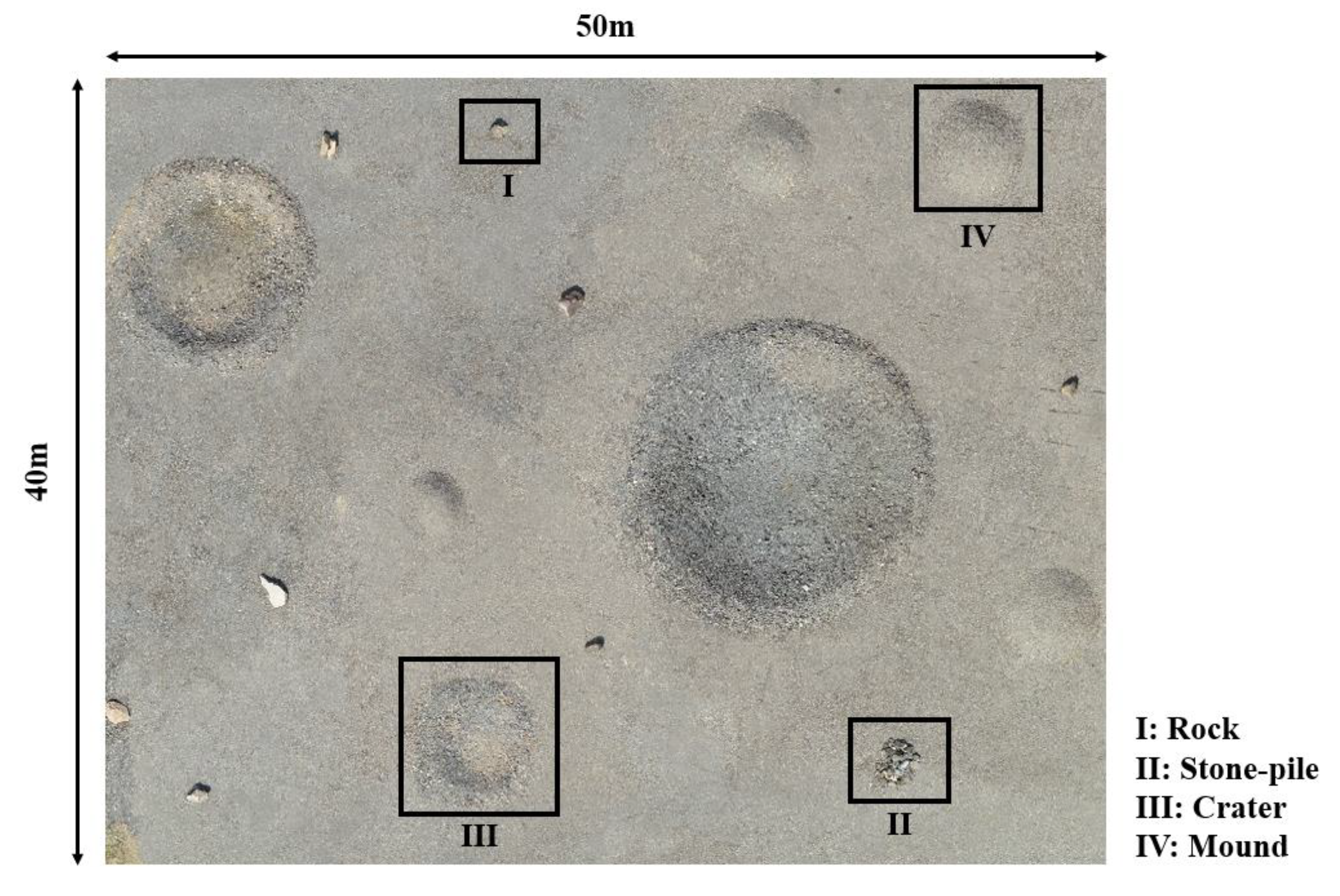
In planetary construction, flat areas with sparse rock distribution are likely to be construction candidate sites due to their topographic and geotechnical feasibility to strengthen the foundation and stabilize the surface [62,63]. The field test site, which is located at the Korea Research Institute of Civil Engineering and Building Technology (KICT) (Figure 4), is designed for robotic mapping systems to simulate a construction mapping process. The dimensions are 40 m × 50 m, and rounded-pile and hollowed-out areas of different sizes are distributed over a flat ground with few rocks. In the experiment, the robotic mapping system slowly traversed the entire test site from noon to late afternoon, occasionally stopping to recognize the current location and find a path to the next terrain feature. In the robotic operation, major terrain features (e.g., rock, crater, and mound) were repeatedly visited from different angles and positions. In the following sections, the terrain image set from the mapping system was used to experimentally select the LLIE method and to create the 3D point-cloud map of the test site.
4.3. Image Enhancement under Varying Illumination Conditions
In the experiment, six different LLIE methods (RetinexNet, DALE, DLN, DSLR, GLAD, KinD) were initially selected and trained on the LOL data set [45]. The LLIE methods were sequentially fine-tuned using 440 image pairs from an emulated terrain in the indoor laboratory, where diverse illumination conditions from a bright level to a dark level could be manually adjusted [64]. Another 60 images were used to validate the LLIE methods. The proposed approach was implemented using Python due to the easy integration of deep learning models. The computation time per image frame was approximately 0.2 s on the graphics processing unit (RTX 3070). Specifically, 0.1 s was used to perform the image enhancement procedure on both stereo image inputs and another 0.1 s for visual tracking with AKAZE [65].
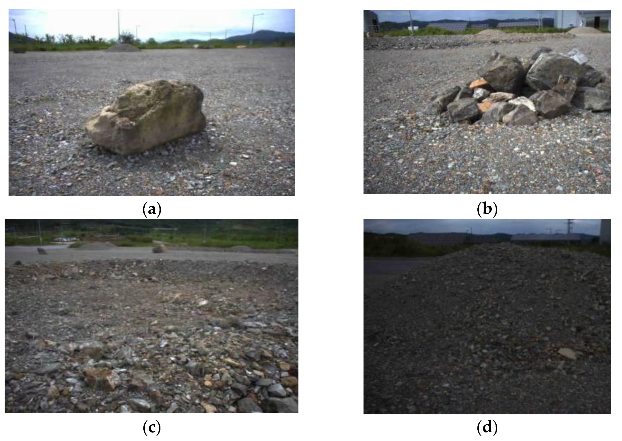
To determine the robust LLIE method, four terrain images under different illumination conditions were obtained from the test site. As cloud coverage and solar altitude continuously change, the terrain images in Figure 5 have a different magnitude of brightness and color property. In Figure 5a, the terrain image was taken under clear sky at noon, in which the rock has a bright color with a shadow. However, the image quality depends on the cloud coverage that reflects the sunlight. In Figure 5b,c, the terrain images become incrementally darker as the cloud coverage increases. In addition, the low solar altitude in the late afternoon caused the onboard camera to become underexposed. The terrain image in Figure 5d consequently has the lowest brightness compared to the other images, with the entire visual content degraded and the mound in the background hardly discernible.
To ensure the image enhancement results from the darkest condition in the image set, the LLIE methods were applied to the terrain image in Figure 5d. The image enhancement results were then evaluated quantitatively and qualitatively, as shown in Table 1 and Figure 6 respectively. In Table 1, Naturalness Image Quality Evaluator (NIQE) [66] and Blind/Referenceless Image Spatial Quality Evaluator (BRISQUE) [67], which are no-reference image evaluation metrics, are used to quantify the enhanced image qualities. NIQE measures the distance between the multivariate Gaussian model of the natural image and the test image. Additionally, BRIQUE evaluates the test image based on natural scene statistics. A smaller score from both NIQE and BRISQUE indicates better visually perceptual quality. Table 1 shows that GLAD is the best method from both evaluation metrics. However, in some cases, different evaluation metrics assign a different score to the same LLIE method in that each metric evaluates different aspects of the enhanced image. For example, NIQE indicates that DLN and Kind achieve the second and third best scores, respectively. However, the second and third best scores in BRISQUE are achieved by DSLR and DLN, respectively.
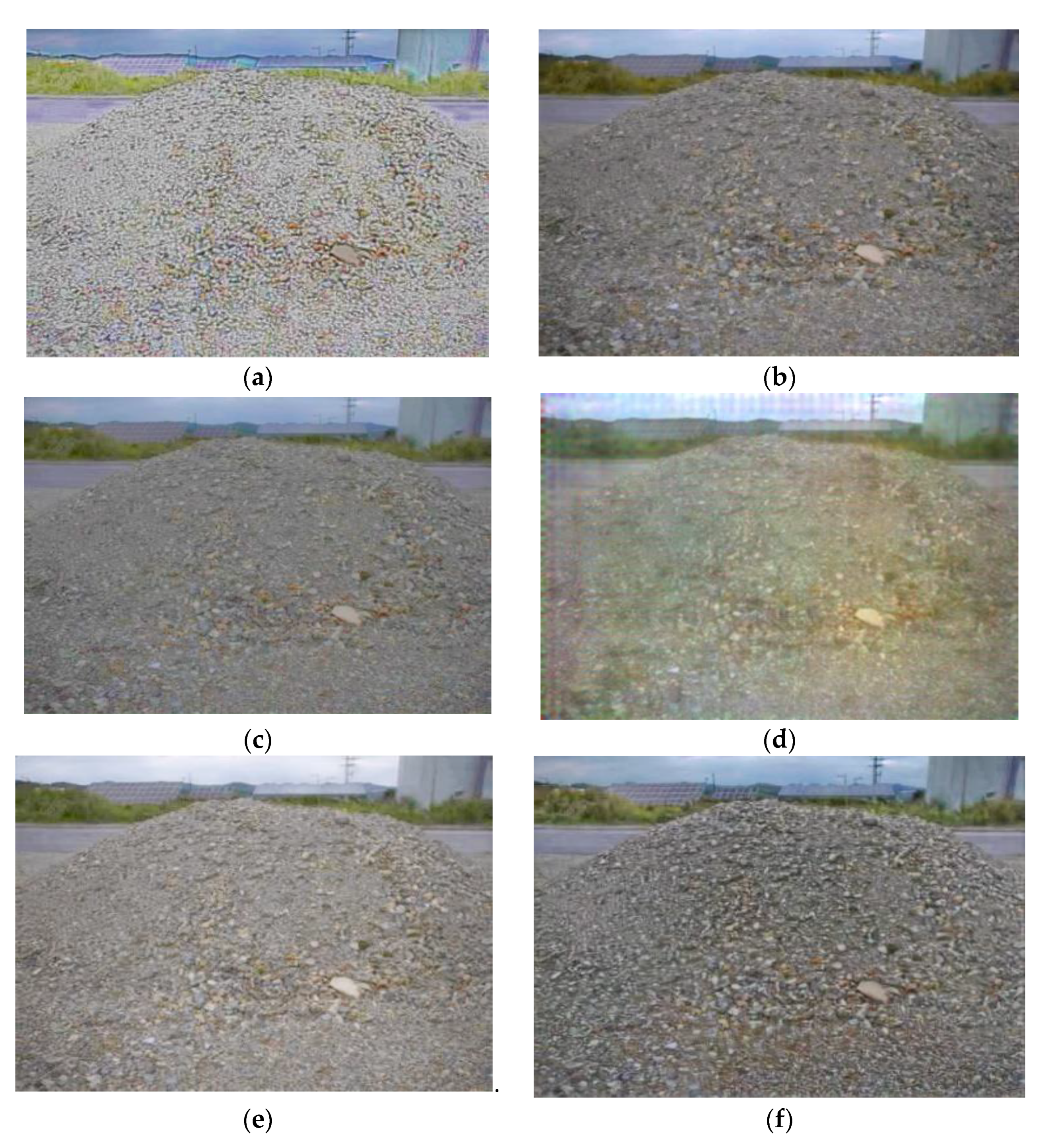
These evaluation metric scores are not completely consistent with subjective human perception; thus, the image enhancement results in Figure 6 is visually inspected. In Figure 6a, RetinexNet severely stylizes and distorts the colors of the terrain features in the image. DSLR in Figure 6 has the second highest score in BRISQUE, but random and gridding artifacts are introduced within the image. Additionally, the entire image is oversmoothed, which causes a loss of detail, especially for the gravels on the mound. In Figure 6d, DALE reveals chromatic distortion surrounding the different artifacts. KinD in Figure 6f improved the contrast, but visible color distortion is shown in the lower part of the mound. Overall, GLAD (Figure 6e) and DLN (Figure 6c) improved the brightness the best, maintaining clarity and color in the darkest conditions in Figure 5.
A second experiment was conducted to ensure consistent color restorations over the terrain images with a different degree of brightness (Figure 5). GLAD and DLN were selected from the first experiment due to their quantitatively and qualitatively stable performances. Additionally, the image brightness is increased without severely degrading the image quality. Figure 7 shows the image enhancement results from the four terrain images in Figure 5. In Figure 7a, DLN generates slightly overexposed images but blurs the extent of terrain features such as gravel, rock, and mound. Additionally, the different brightness is obviously observed when the first and last images are compared. However, in Figure 7b, GLAD tends to demonstrate consistent color enhancement over all images, maintaining the image quality. Additionally, the features in each image can be clearly identified in comparison to those in the DLN-enhanced images. Therefore, GLAD is eventually selected for enhancing the entire terrain image frames from the robotic mapping system.
4.4. Robotic Mapping Results
Similar to construction on Earth, the first phase in planetary construction is site preparation. The teleoperated construction robots are then employed to clear and grade the ground before emplacing infrastructure such as roads, landing pads, and ISRU utilities. Therefore, to understand the terrain morphological characteristics of the worksite, on-site robotic mapping is essential to create a highly detailed and accurate point-cloud map.
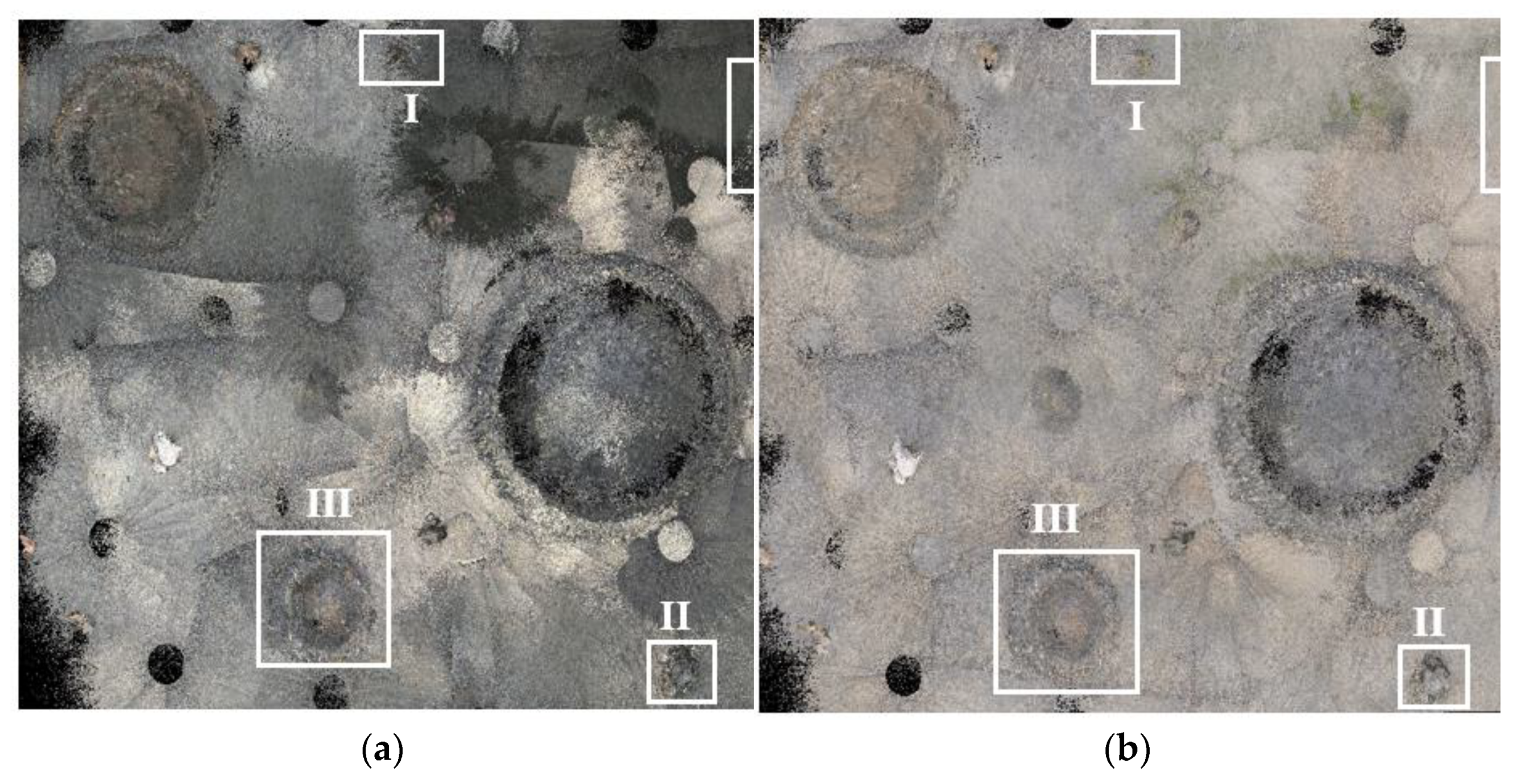
The proposed mapping method sequentially involved enhanced image pairs from GLAD. Three-dimensional (3D) point clouds were then generated along the rover trajectory, by which the test site in Figure 8 was reconstructed as a mapping result. In Figure 9, the original and enhanced point-cloud maps are shown for comparison purposes. Multiple circles in both point-cloud maps are blind spots that were inevitably made when the rover-mounted camera was fully rotated. Additionally, to build the point-cloud map, the rover slowly traversed around the entire test site, repeatedly visiting the same locations. Terrain images were continuously influenced by changes in cloud coverage and solar altitude from noon to late afternoon. Therefore, in Figure 9a, the original point-cloud map consequently has the mixed nature of colors from beige to dark gray. However, in Figure 9), the LLIE method visually improved the original terrain images to have relatively brighter and more consistent colors irrespective of the illumination condition changes. Shapes and distributions of terrain features (e.g., mound, crater) and obstacles (e.g., rock) are easily identified in the enhanced point-cloud map.
In Figure 10 and Figure 11, point clouds of the rock, stone pile, crater, and mound in both point-cloud maps are selected for visual inspection, each of which is indexed in Figure 8 and Figure 9. In the robotic mapping process, images of the same feature were taken from different angles and distances. Point clouds are repeatedly created, blurring the outlines of the terrain features. Therefore, even though images were obtained in better lighting conditions, small features (e.g., pebble and stone) in all point clouds are hardly discernible in Figure 10 and Figure 11. However, in Figure 10, the perceptual appearance of terrain features is degraded by the dark colors of the point clouds. Images of the stone pile were taken under partial or full cloud coverage, and therefore, its appearance has distorted color properties with indistinct outlines. Furthermore, the mound has an empty space on the top due to the lower height of the rover-mounted camera system. Although prior knowledge is given from the terrain image, the defects in point clouds make it more difficult to identify the mound from the background. In contrast, Figure 11 shows that the overall qualities of the point clouds are significantly improved, especially for the stone pile and the mound. The rock, stone pile, and crater still have blurred outlines, but the enhanced image set creates point clouds closer to their natural appearances, preserving inherent colors and details. Additionally, for the mound, the brightness of the point clouds is enhanced while restoring the colors from dark gray to beige. The visual perception is much improved when the mounds in Figure 10 and Figure 11 are compared to each other.
Accuracy assessment was conducted to investigate the influence of the enhanced images on the quality of the point-cloud map. Terrestrial LiDAR (Trimble X7) was employed to obtain the point cloud as a reference, to which the iterative closest point (ICP) was used to optimally align the point-cloud maps in Figure 9. The root mean square error (RMSE) measurements for the original and enhanced point-cloud maps are 0.29 m and 0.25 m, respectively. As the test site has a flat and smooth surface, the enhanced image set does not lead to a significant reduction in RMSE measurements. To rigorously analyze the positional errors, the positional error distribution is geographically represented along with the positional error histogram in Figure 12. The color index, ranging from blue to yellow-green, represents the magnitude of positional errors along the x-axis of the histogram. Generally, positional errors in both point-cloud maps are not uniformly distributed over the test site. As the robotic mapping system mostly moved around the center of the test site, positional errors in the marginal areas are often larger than the central area. However, when the positional error distributions and histograms in Figure 12a,b are compared, the enhanced point-cloud map has a larger blue extent, and its histogram has a narrower width. Accuracy assessment results indicate that the enhanced image set increases the overall accuracy of the original point clouds.
5. Discussion and Conclusions
Many space agencies worldwide have renewed their planetary exploration roadmap to return humans to the surfaces of the Moon and Mars. Numerous ideas and proposals have been presented to build a planetary base for sustained human exploration and habitation. Planetary construction implies that various types of construction robots will repeatedly visit the same worksite to perform complex tasks such as excavation, grading, leveling, and additive construction. These robotic construction operations solely rely on images from the onboard camera system. However, illumination conditions may vary for each visit due to illumination-variant conditions such as solar altitudes and different weather, especially for Mars. The inconsistent color property of images hampers the ability to recognize terrain features, even at the returned location. Additionally, in the unknown environments of worksites, prior knowledge of detailed topographic information is essential for construction planning and management. It is critical to ensure that images from robots are maintained in bright and consistent colors despite continually changing illumination conditions.
The proposed robotic mapping approach for planetary construction aims to build a 3D dense point-cloud map that depicts the worksite with perceptually color-consistent properties. In the proposed approach, the stereo SLAM-based robotic mapping method, which is based on S-PTAM, is combined with the LLIE method to enhance mapping capabilities. The robotic mapping system, which was deployed at the emulated planetary worksite, collected terrain images in a topographic surveying manner. All terrain images were collected during the daytime from noon to late afternoon. However, changes in weather and solar altitude resulted in the terrain images having inconsistent colors and consequently affected the point-cloud map. Dark point clouds hid many terrain features of interest, making it difficult to understand the topographic properties of the test site. Therefore, the deep-learning-based LLIE method was experimentally selected, enabling the original terrain images to have structural consistency with improved brightness and color. The enhanced point-cloud map was then created and compared with the original point-cloud map. The experiment results indicate that the robotic mapping method leverages the LLIE method to improve the visibility and the overall accuracy of the original point-cloud map. The brightness of the original point-cloud map was significantly improved, preserving inherent colors and details. Additionally, the point-cloud map became closer to the natural appearance of the test site.
The proposed approach shows promising results for planetary construction mapping. Additionally, color restoration and consistent imagery have potential for use in scientific investigations, such as geologic mapping. However, path planning, along with global localization, is another concern to minimize robot motions for efficient mapping and to historically align updated mapping results for construction monitoring. In addition, technical constraints still remain for implementation. In the planetary construction process, humans and robots are required to repetitively visit the worksite. The terrain image set is then accumulated to fine-tune the LLIE methods for future robots. However, the LLIE method in the proposed approach requires robots to use a large image set for training purposes. Additionally, during mapping, a disparity map is computed at a high frame rate. Heavy computation and a large data set pose great challenges to its application. The proposed approach should be adjusted to be more lightweight and optimized with respect to technical progress on the mechanical and hardware components of future planetary construction robots.
Author Contributions
Conceptualization, S.H.; methodology, P.S., S.H., A.B. and H.S.; validation, S.H.; formal analysis, S.H. and P.S.; resources, H.S.; data curation, P.S. and A.B.; writing—original draft preparation, S.H. and P.S.; writing—review and editing, S.H., P.S. and A.B; supervision, S.H.; project administration, H.S.; funding acquisition, H.S. All authors have read and agreed to the published version of the manuscript.
Funding
This research was supported by the research project “Development of environmental simulator and advanced construction technologies over TRL6 in extreme conditions” funded by Korea Institute of Civil Engineering and Building Technology.
Data Availability Statement
Not applicable.
Acknowledgments
This research was supported by the research project “Development of environmental simulator and advanced construction technologies over TRL6 in extreme conditions” funded by Korea Institute of Civil Engineering and Building Technology and an Inha University research grant.
Conflicts of Interest
The authors declare no conflict of interest.
References
- ISECG. Global Exploration Roadmap Supplement; Lunar Surface Exploration Scenario Update. Available online: https://www.globalspaceexploration.org/?p=1049 (accessed on 10 January 2022).
- Arya, A.S.; Rajasekhar, R.P.; Thangjam, G.A.; Kumar, A.K. Detection of potential site for future human habitability on the Moon using Chandrayaan-1 data. Curr. Sci. 2011, 100, 524–529. [Google Scholar]
- Spudis, P.; Bussey, D.; Baloga, S.; Cahill, J.; Glaze, L.; Patterson, G.; Raney, R.; Thompson, T.; Thomson, B.; Ustinov, E. Evidence for water ice on the Moon: Results for anomalous polar craters from the LRO Mini-RF imaging radar. J. Geophys. Res. Planets 2013, 118, 2016–2029. [Google Scholar] [CrossRef]
- Ralphs, M.; Franz, B.; Baker, T.; Howe, S. Water extraction on Mars for an expanding human colony. Life Sci. Space Res. 2015, 7, 57–60. [Google Scholar] [CrossRef]
- Thangavelautham, J.; Robinson, M.S.; Taits, A.; McKinney, T.; Amidan, S.; Polak, A. Flying, hopping Pit-Bots for cave and lava tube exploration on the Moon and Mars. arXiv Preprint 2017, arXiv:1701.07799. [Google Scholar]
- Li, S.; Lucey, P.G.; Milliken, R.E.; Hayne, P.O.; Fisher, E.; Williams, J.-P.; Hurley, D.M.; Elphic, R.C. Direct evidence of surface exposed water ice in the lunar polar regions. Proc. Natl. Acad. Sci. USA 2018, 115, 8907–8912. [Google Scholar] [CrossRef] [Green Version]
- Deutsch, A.N.; Head, J.W., III; Neumann, G.A. Analyzing the ages of south polar craters on the Moon: Implications for the sources and evolution of surface water ice. Icarus 2020, 336, 113455. [Google Scholar] [CrossRef]
- Piqueux, S.; Buz, J.; Edwards, C.S.; Bandfield, J.L.; Kleinböhl, A.; Kass, D.M.; Hayne, P.O.; MCS; THEMIS Teams. Widespread shallow water ice on Mars at high latitudesand midlatitudes. Geophys. Res. Lett. 2019, 46, 14290–14298. [Google Scholar] [CrossRef]
- Titus, T.N.; Kieffer, H.H.; Christensen, P.R. Exposed water ice discovered near the south pole of Mars. Science 2003, 299, 1048–1051. [Google Scholar] [CrossRef]
- Anand, M.; Crawford, I.A.; Balat-Pichelin, M.; Abanades, S.; Van Westrenen, W.; Péraudeau, G.; Jaumann, R.; Seboldt, W. A brief review of chemical and mineralogical resources on the Moon and likely initial In Situ Resource Utilization (ISRU) applications. Planet. Space Sci. 2012, 74, 42–48. [Google Scholar] [CrossRef]
- Arney, D.C.; Jones, C.A.; Klovstad, J.; Komar, D.; Earle, K.; Moses, R.; Bushnell, D.; Shyface, H. Sustaining Human Presence on Mars Using ISRU and a Reusable Lander. In Proceedings of the AIAA Space 2015 Conference and Exposition, Pasadena, CA, 31 August–2 September 2015; p. 4479. [Google Scholar]
- Naser, M. Extraterrestrial construction materials. Prog. Mater. Sci. 2019, 105, 100577. [Google Scholar] [CrossRef]
- Lee, W.-B.; Ju, G.-H.; Choi, G.-H.; Sim, E.-S. Development Trends of Space Robots. Curr. Ind. Technol. Trends Aerosp. 2011, 9, 158–175. [Google Scholar]
- Khoshnevis, B. Automated construction by contour crafting—Related robotics and information technologies. Autom. Constr. 2004, 13, 5–19. [Google Scholar] [CrossRef]
- Khoshnevis, B.; Yuan, X.; Zahiri, B.; Zhang, J.; Xia, B. Construction by Contour Crafting using sulfur concrete with planetary applications. Rapid Prototyp. J. 2016, 22, 848–856. [Google Scholar] [CrossRef] [Green Version]
- Cesaretti, G.; Dini, E.; De Kestelier, X.; Colla, V.; Pambaguian, L. Building components for an outpost on the Lunar soil by means of a novel 3D printing technology. Acta Astronaut. 2014, 93, 430–450. [Google Scholar] [CrossRef]
- Roman, M.; Yashar, M.; Fiske, M.; Nazarian, S.; Adams, A.; Boyd, P.; Bentley, M.; Ballard, J. 3D-printing lunar and martian habitats and the potential applications for additive construction. In Proceedings of the International Conference on Environmental Systems, Lisbon, Portugal, 31 July 2020. [Google Scholar]
- Kelso, R.; Romo, R.; Andersen, C.; Mueller, R.; Lippitt, T.; Gelino, N.; Smith, J.; Townsend, I.I.; Schuler, J.; Nugent, M. Planetary Basalt Field Project: Construction of a Lunar Launch/Landing Pad, PISCES and NASA Kennedy space center project update. In Earth and Space 2016: Engineering for Extreme Environments; American Society of Civil Engineers: Reston, VA, USA, 2016; pp. 653–667. [Google Scholar]
- Mueller, R.; Fikes, J.C.; Case, M.P.; Khoshnevis, B.; Fiske, M.R.; Edmunson, J.; Kelso, R.; Romo, R.; Andersen, C. Additive construction with mobile emplacement (ACME). In Proceedings of the 68th International Astronautical Congress (IAC), Adelaide, Australia, 25–29 September 2017; pp. 25–29. [Google Scholar]
- Jawin, E.R.; Valencia, S.N.; Watkins, R.N.; Crowell, J.M.; Neal, C.R.; Schmidt, G. Lunar science for landed missions workshop findings report. Earth Space Sci. 2019, 6, 2–40. [Google Scholar] [CrossRef] [Green Version]
- Pajola, M.; Rossato, S.; Baratti, E.; Kling, A. Planetary mapping for landing sites selection: The Mars Case Study. In Planetary Cartography and GIS; Springer: Cham, Switzerland, 2019; pp. 175–190. [Google Scholar]
- Tong, C.H.; Barfoot, T.D.; Dupuis, É. Three-dimensional SLAM for mapping planetary work site environments. J. Field Robot. 2012, 29, 381–412. [Google Scholar] [CrossRef]
- Merali, R.S.; Tong, C.; Gammell, J.; Bakambu, J.; Dupuis, E.; Barfoot, T.D. 3D surface mapping using a semiautonomous rover: A planetary analog field experiment. In Proceedings of the 2012 International Symposium on Artificial Intelligence, Robotics and Automation in Space (i-SAIRAS), Fort Lauderdale, Florida, USA, 9–11 January 2012. [Google Scholar]
- Shaukat, A.; Blacker, P.C.; Spiteri, C.; Gao, Y. Towards camera-LIDAR fusion-based terrain modelling for planetary surfaces: Review and analysis. Sensors 2016, 16, 1952. [Google Scholar] [CrossRef] [Green Version]
- Schuster, M.J.; Brunner, S.G.; Bussmann, K.; Büttner, S.; Dömel, A.; Hellerer, M.; Lehner, H.; Lehner, P.; Porges, O.; Reill, J. Towards autonomous planetary exploration. J. Intell. Robot. Syst. 2019, 93, 461–494. [Google Scholar] [CrossRef] [Green Version]
- Bajpai, A.; Burroughes, G.; Shaukat, A.; Gao, Y. Planetary monocular simultaneous localization and mapping. J. Field Robot. 2016, 33, 229–242. [Google Scholar] [CrossRef]
- Tseng, K.-K.; Li, J.; Chang, Y.; Yung, K.; Chan, C.; Hsu, C.-Y. A new architecture for simultaneous localization and mapping: An application of a planetary rover. Enterp. Inf. Syst. 2021, 15, 1162–1178. [Google Scholar] [CrossRef]
- Lemaire, T.; Berger, C.; Jung, I.-K.; Lacroix, S. Vision-based slam: Stereo and monocular approaches. Int. J. Comput. Vis. 2007, 74, 343–364. [Google Scholar] [CrossRef]
- Hidalgo-Carrió, J.; Poulakis, P.; Kirchner, F. Adaptive localization and mapping with application to planetary rovers. J. Field Robot. 2018, 35, 961–987. [Google Scholar] [CrossRef]
- Hummel, R. Image enhancement by histogram transformation Comp. Graph. Image Process 1975, 6, pp. 184–195. [Google Scholar] [CrossRef]
- Ketcham, D.J. Real-Time Image Enhancement Techniques. In Proceedings of the Image Processing, International Society for Optics and Photonics. Pacific Grove, CA, USA, 9 July 1976; pp. 120–125. [Google Scholar]
- Zuiderveld, K. Contrast limited adaptive histogram equalization. In Graphics gems IV; Academic Press: Cambridge, MA, USA, 1994; pp. 474–485. [Google Scholar]
- Kim, Y.-T. Contrast enhancement using brightness preserving bi-histogram equalization. IEEE Trans. Consum. Electron. 1997, 43, 1–8. [Google Scholar]
- Wang, Y.; Chen, Q.; Zhang, B. Image enhancement based on equal area dualistic sub-image histogram equalization method. IEEE Trans. Consum. Electron. 1999, 45, 68–75. [Google Scholar] [CrossRef]
- Sim, K.; Tso, C.; Tan, Y. Recursive sub-image histogram equalization applied to gray scale images. Pattern Recognit. Lett. 2007, 28, 1209–1221. [Google Scholar] [CrossRef]
- Chen, S.-D.; Ramli, A.R. Preserving brightness in histogram equalization based contrast enhancement techniques. Digit. Signal Process. 2004, 14, 413–428. [Google Scholar] [CrossRef]
- Land, E.H. The retinex theory of color vision. Sci. Am. 1977, 237, 108–129. [Google Scholar] [CrossRef]
- Jobson, D.J.; Rahman, Z.-u.; Woodell, G.A. Properties and performance of a center/surround retinex. IEEE Trans. Image Process. 1997, 6, 451–462. [Google Scholar] [CrossRef]
- Jobson, D.J.; Rahman, Z.-u.; Woodell, G.A. A multiscale retinex for bridging the gap between color images and the human observation of scenes. IEEE Trans. Image Process. 1997, 6, 965–976. [Google Scholar] [CrossRef] [Green Version]
- Wang, S.; Zheng, J.; Hu, H.-M.; Li, B. Naturalness preserved enhancement algorithm for non-uniform illumination images. IEEE Trans. Image Process. 2013, 22, 3538–3548. [Google Scholar] [CrossRef] [PubMed]
- Fu, X.; Zeng, D.; Huang, Y.; Zhang, X.-P.; Ding, X. A weighted variational model for simultaneous reflectance and illumination estimation. In Proceedings of the IEEE Conference on Computer Vision and Pattern Recognition, Las Vegas, NV, USA, 27–30 June 2016; pp. 2782–2790. [Google Scholar]
- Guo, X.; Li, Y.; Ling, H. LIME: Low-light image enhancement via illumination map estimation. IEEE Trans. Image Process. 2016, 26, 982–993. [Google Scholar] [CrossRef] [PubMed]
- Lore, K.G.; Akintayo, A.; Sarkar, S. LLNet: A deep autoencoder approach to natural low-light image enhancement. Pattern Recognit. 2017, 61, 650–662. [Google Scholar] [CrossRef] [Green Version]
- Li, C.; Guo, J.; Porikli, F.; Pang, Y. LightenNet: A convolutional neural network for weakly illuminated image enhancement. Pattern Recognit. Lett. 2018, 104, 15–22. [Google Scholar] [CrossRef]
- Wei, C.; Wang, W.; Yang, W.; Liu, J. Deep retinex decomposition for low-light enhancement. arXiv Preprint 2018, arXiv:1808.04560. [Google Scholar]
- Lv, F.; Lu, F.; Wu, J.; Lim, C. MBLLEN: Low-light image/video enhancement using CNNs. In Proceedings of the BMVC, Newcastle, UK, 3–6 September 2018; p. 220. [Google Scholar]
- Prabhakar, K.R.; Srikar, V.S.; Babu, R.V. DeepFuse: A deep unsupervised approach for exposure fusion with extreme exposure image Pairs. In Proceedings of the ICCV, Venice, Italy, 22–29 October 2017; p. 3. [Google Scholar]
- Jiang, Y.; Gong, X.; Liu, D.; Cheng, Y.; Fang, C.; Shen, X.; Yang, J.; Zhou, P.; Wang, Z. Enlightengan: Deep light enhancement without paired supervision. arXiv Preprint 2019, arXiv:1906.06972. [Google Scholar] [CrossRef]
- Kim, G.; Kwon, D.; Kwon, J. Low-lightgan: Low-light enhancement via advanced generative adversarial network with task-driven training. In Proceedings of the 2019 IEEE International Conference on Image Processing (ICIP), Taipei, Taiwan, 22–25 September 2019; pp. 2811–2815. [Google Scholar]
- Kwon, D.; Kim, G.; Kwon, J. DALE: Dark region-aware low-light image enhancement. arXiv Preprint 2008, arXiv:12493 2020. [Google Scholar]
- Wang, X.; Christie, M.; Marchand, E. Optimized contrast enhancements to improve robustness of visual tracking in a SLAM relocalisation context. In Proceedings of the 2018 IEEE/RSJ International Conference on Intelligent Robots and Systems (IROS), Madrid, Spain, 1–5 October 2018; pp. 103–108. [Google Scholar]
- Sun, P.; Lau, H.Y. RGB-Channel-based Illumination Robust SLAM Method. J. Control Autom. Eng. 2019, 7, 61–69. [Google Scholar] [CrossRef]
- Lee, H.S.; Park, J.M.; Hong, S.; Shin, H.-S. Low light image enhancement to construct terrain information from permanently shadowed region on the moon. J. Korean Soc. Geospat. Inf. Syst. 2020, 28, 41–48. [Google Scholar]
- Fan, W.; Huo, Y.; Li, X. Degraded image enhancement using dual-domain-adaptive wavelet and improved fuzzy transform. Math. Probl. Eng. 2021, 2021, 1–12. [Google Scholar] [CrossRef]
- Gomez-Ojeda, R.; Zhang, Z.; Gonzalez-Jimenez, J.; Scaramuzza, D. Learning-based image enhancement for visual odometry in challenging HDR environments. In Proceedings of the 2018 IEEE International Conference on Robotics and Automation (ICRA), Brisbane, QLD, Australia, 21–25 May 2018; pp. 805–811. [Google Scholar]
- Jung, E.; Yang, N.; Cremers, D. Multi-frame GAN: Image enhancement for stereo visual odometry in low light. In Proceedings of the Conference on Robot Learning, 16–18 November 2020; pp. 651–660. [Google Scholar]
- Hu, J.; Guo, X.; Chen, J.; Liang, G.; Deng, F.; Lam, T.L. A two-stage unsupervised approach for low light image enhancement. IEEE Robot. Autom. Lett. 2021, 6, 8363–8370. [Google Scholar] [CrossRef]
- Hong, S.; Bangunharcana, A.; Park, J.-M.; Choi, M.; Shin, H.-S. Visual SLAM-based robotic mapping method for planetary construction. Sensors 2021, 21, 7715. [Google Scholar] [CrossRef] [PubMed]
- Pire, T.; Fischer, T.; Castro, G.; De Cristóforis, P.; Civera, J.; Berlles, J.J. S-PTAM: Stereo parallel tracking and mapping. Robot. Auton. Syst. 2017, 93, 27–42. [Google Scholar] [CrossRef] [Green Version]
- Zhong, Y.; Dai, Y.; Li, H. Self-supervised learning for stereo matching with self-improving ability. arXiv Preprint 2017, arXiv:1709.00930. [Google Scholar]
- Loza, A.; Mihaylova, L.; Canagarajah, N.; Bull, D. Structural similarity-based object tracking in video sequences. In Proceedings of the 2006 9th International Conference on Information Fusion, Florence, Italy, 10–13 July 2006; pp. 1–6. [Google Scholar]
- Bussey, B.; Hoffman, S.J. Human Mars landing site and impacts on Mars surface operations. In Proceedings of the 2016 IEEE Aerospace Conference, Big Sky, MT, USA, 5–12 March 2016; pp. 1–21. [Google Scholar]
- Green, R.D.; Kleinhenz, J.E. In-situ resource utilization (ISRU) Living off the Land on the Moon and Mars. In Proceedings of the American Chemical Society National Meeting & Exposition, Oraldo, FL, USA, 31 March–4 April 2019; pp. 1–4. [Google Scholar]
- Hong, S.; Shin, H.-S. Construction of indoor and outdoor testing environments to develop rover-based lunar geo-spatial information technology. In Proceedings of the the KSCE Conference, Jeju, Korea, 10–23 October 2020; pp. 455–456. [Google Scholar]
- Alcantarilla, P.F.; Solutions, T. Fast explicit diffusion for accelerated features in nonlinear scale spaces. IEEE Trans. Pattern Anal. Mach. Intell. 2011, 34, 1281–1298. [Google Scholar]
- Mittal, A.; Soundararajan, R.; Bovik, A.C. Making a ″completely blind″ image quality analyzer. IEEE Signal Process. Lett. 2012, 20, 209–212. [Google Scholar] [CrossRef]
- Mittal, A.; Moorthy, A.K.; Bovik, A.C. No-reference image quality assessment in the spatial domain. IEEE Trans. Image Process. 2012, 21, 4695–4708. [Google Scholar] [CrossRef]
Figure 1.
Planetary base and ISRU facilities for human presence.

Figure 2.
Conceptual process of the robotic construction mapping method.

Figure 3.
Robotic mapping system.

Figure 4.
Emulated planetary worksite (test site).

Figure 5.
Terrain images with decreasing illumination conditions (a–d): (a) bright condition with clear sky at noon; (b) overcast condition, partly cloudy in the afternoon; (c) overcast condition with full cloud coverage in the afternoon; (d) darkest condition with low solar altitude in the late afternoon.

Figure 6.
Darkest image enhancement results in the test image in Figure 5d: (a) RetinexNet; (b) DALE; (c) DLN; (d) DSLR; (e) GLAD; (f) KinD.
Figure 6.
Darkest image enhancement results in the test image in Figure 5d: (a) RetinexNet; (b) DALE; (c) DLN; (d) DSLR; (e) GLAD; (f) KinD.

Figure 7.
Image enhancement results over the test images in Figure 5: (a) DLN; (b) GLAD.
Figure 7.
Image enhancement results over the test images in Figure 5: (a) DLN; (b) GLAD.

Figure 8.
Aerial photo of the test site.

Figure 9.
Robotic mapping results to terrain images from the robotic mapping system: (a) original point-cloud map; (b) enhanced point-cloud map.
Figure 9.
Robotic mapping results to terrain images from the robotic mapping system: (a) original point-cloud map; (b) enhanced point-cloud map.

Figure 10.
Terrain features selected from original point cloud in Figure 9.
Figure 10.
Terrain features selected from original point cloud in Figure 9.

Figure 11.
Terrain features selected from the enhanced point-cloud maps in Figure 9.
Figure 11.
Terrain features selected from the enhanced point-cloud maps in Figure 9.

Figure 12.
Positional error histogram (left) and positional error distribution over the test site (right). Identical color index is used to represent a magnitude of positional errors in the original and enhanced point-cloud maps: (a) positional errors in the original point-cloud map; (b) positional errors in the enhanced point-cloud map.


Table 1.
Performance of different models on dark images.
| LLIE methods | NIQE | BRISQUE |
|---|---|---|
| RetinexNet | 5.48 | 67.40 |
| DALE | 8.40 | 65.56 |
| DLN | 4.27 | 55.74 |
| DSLR | 5.07 | 52.38 |
| GLAD | 3.82 | 45.33 |
| KinD | 4.67 | 60.60 |
Publisher’s Note: MDPI stays neutral with regard to jurisdictional claims in published maps and institutional affiliations. |
© 2022 by the authors. Licensee MDPI, Basel, Switzerland. This article is an open access article distributed under the terms and conditions of the Creative Commons Attribution (CC BY) license (https://creativecommons.org/licenses/by/4.0/).
Share and Cite
MDPI and ACS Style
Hong, S.; Shyam, P.; Bangunharcana, A.; Shin, H. Robotic Mapping Approach under Illumination-Variant Environments at Planetary Construction Sites. Remote Sens. 2022, 14, 1027. https://0-doi-org.brum.beds.ac.uk/10.3390/rs14041027
AMA Style
Hong S, Shyam P, Bangunharcana A, Shin H. Robotic Mapping Approach under Illumination-Variant Environments at Planetary Construction Sites. Remote Sensing. 2022; 14(4):1027. https://0-doi-org.brum.beds.ac.uk/10.3390/rs14041027
Chicago/Turabian StyleHong, Sungchul, Pranjay Shyam, Antyanta Bangunharcana, and Hyuseoung Shin. 2022. "Robotic Mapping Approach under Illumination-Variant Environments at Planetary Construction Sites" Remote Sensing 14, no. 4: 1027. https://0-doi-org.brum.beds.ac.uk/10.3390/rs14041027
Note that from the first issue of 2016, this journal uses article numbers instead of page numbers. See further details here.