Article

Study on the Light Field Regulation of UVC-LED Disinfection for Cold Chain Transportation

1
Beijing Institute of Technology, School of Mechanical Engineering, No.5 Zhongguancun South Street, Haidian District, Beijing 100081, China
2
Chongqing Innovation Center, Beijing Institute of Technology, Chongqing 401120, China
3
Institute of Engineering Medicine, Beijing Institute of Technology, No.5 Zhongguancun South Street, Haidian District, Beijing 100081, China
4
Department of Clinical Laboratory, The 7th Medical Center, Chinese PLA General Hospital, Beijing 100853, China
5
Beijing Institute of Technology, School of Optics and Photonics, No.5 Zhongguancun South Street, Haidian District, Beijing 100081, China
*
Author to whom correspondence should be addressed.
These authors contributed equally to this paper as first authors.
Submission received: 15 December 2021 / Revised: 17 January 2022 / Accepted: 19 January 2022 / Published: 26 January 2022
(This article belongs to the Collection Optical Design and Engineering)

Abstract

:
In this paper, the pain point that cold chain transportation urgently needs for an efficient disinfection method is pointed out. Thus, this work aims at solving the problems and improving the disinfection efficiency in cold chain transportation. While Ultraviolet-C (UVC) irradiation is an effective method by which to kill viruses, it is difficult to apply the commonly used UVC-LED disinfection light source to ice-covered cold chain transportation due to its uneven light field distribution. Thus, the light field regulation of UVC-LED disinfection for cold chain transportation is studied. A UVC-LED chip with a wavelength of 275 nm was used as a light source, and parallel light was obtained by collimating lenses. Then, microlens array homogenization technology was used to shape the UVC light into a uniform light spot, with an energy space uniformity rate of 96.4%. Moreover, a simulation was conducted to compare the effects of the ice layer on the absorption of UVC light. Finally, an experiment was carried out to verify that the disinfection efficiency can be increased nearly by 30% with the proposed system by disinfecting E. coli (Escherichia coli), and the results indicate that the proposed system is an effective disinfection solution during cold chain transportation.

1. Introduction

Since 2019, the COVID-19 virus has spread globally, and the main transmission mode is cold chain transportation. There have been many cases of cold chain transportation leading to the spread of COVID-19 around the world, which has had severe consequences [1,2]. Therefore, it is necessary to kill viruses in cold chain transportation, including COVID-19 or other viruses. However, disinfection is difficult to complete in cold chain transportation, which is mainly caused by the following reasons. Firstly, viruses and bacteria are more likely to survive at low temperature [3]. Experiments show that most viruses can survive for 1 month at 4 °C. Moreover, when the temperature is lowered to freezing, the viruses can survive stably for several years, while the biological structure of the viruses will not be damaged during survival [4]. At the same time, the viruses still have the possibility of transmission after leaving the freezing environment; then, at low temperature, ice may form on the packaging. The existence of ice makes the disinfection situation more complicated, which will be discussed later; in addition, cold chain transportation involves many links, making the transmission routes of viruses and bacteria wider. All these bring great difficulties to disinfection in the process of cold chain transportation.
In this paper, inspired by the spread of COVID-19 triggered by cold chain transportation, the pain point that cold chain transportation urgently needs for an efficient disinfection method is pointed out. In view of the method of Ultraviolet-C (UVC) disinfection, the difficulties caused by the existence of an ice layer are analyzed in detail through simulation. Secondly, aiming at the shortcomings of the UVC-LED disinfection method and the difficulties of crossing the ice, the light field regulation is studied, and a uniform UVC-LED disinfection system is proposed. Finally, the results of a simulation and a biological experiment are reported to verify the proposed design. In this paper, Section 2 introduces the previous relevant studies and which of those methods are used in the paper. Section 3 presents the whole methodological approach in this paper (simulation modeling of ice influence, design of the proposed optical system, preparation of the experiments). Section 4 analyzes the results in detail (results of simulations on ice influence, results of optical simulation based on the proposed system, results of the experiments). Then, discussions and conclusions are drawn in Section 5.

2. Background

There are several disinfection methods used in cold chain transportation, such as chemical disinfection, ozone disinfection, UV disinfection and so on. Chemical disinfection is often used to disinfect non-food goods in cold chain transportation. Its principle is to kill all microbial propagules and spores in the medium. Ozone disinfection and radiation disinfection are effective disinfection methods. Chen et al. [5] employed an efficient cold atmospheric plasma (CAP) with argon feed gas to inactivate SARS-CoV-2 on various surfaces and achieved great results. Zhang et al. [6] applied surface discharge plasma treated air to deactivate the pseudo virus with the SARS-CoV-2S protein, which also provided a potential disinfection method. In contrast, the process of UV disinfection will not produce pungent odor and will not produce any chemical residues [7]; thus, it is an effective disinfection method in cold chain transportation.
UV (ultraviolet) light in the band of 200–280 nm is UVC light, and UVC disinfection is a mature disinfection method. The principle is to use UVC light to destroy the DNA or RNA molecular structure in microorganism cells, thereby halting cell growth or regeneration and ultimately achieving the effect of disinfection [8]. Shin et al. [9] examined the basic spectral properties of DUV-LEDs (Deep Ultraviolet) and the effects of UVC irradiation for inactivating foodborne pathogens, finding that the use of DUV-LEDs may compensate for the drawbacks of using LP-UV (low-pressure mercury UV) lamps to inactivate foodborne pathogens. Liang et al. [10] examined the efficacy of UVC light prototype devices with the wavelengths of 275, 254, and 222 nm, and drew the conclusion that the UVC-LED (275 nm) exhibited superior SARS-CoV-2 disinfection activity compared to the mercury lamp (254 nm) and the excimer lamp (222 nm). Heilinglog [11] determined the susceptibility of SARS-CoV-2 to UVC light. As a result, a viral stock with a high infectious titer of 5 × 10⁶ TCID50/mL was completely inactivated by UVC irradiation after 9 min, while the dose required for complete inactivation was 1048 mJ·cm−2. Kitagawa [12] investigated the in vitro efficacy of 222-nm far-ultraviolet light (UVC) on the disinfection of SARS-CoV-2 surface contamination. They also investigated the titer of SARS-CoV-2 after UV irradiation (0.1 mW·cm−2) at 222 nm for 10–300 s using the 50% tissue culture infectious dose (TCID50). The results indicated that 222-nm UVC irradiation (0.1 mW·cm−2 for 10 and 30 s) resulted in an 88.5 and 99.7% reduction of viable SARS-CoV-2 based on the TCID50 assay, respectively. There are many other studies that indicate that UVC disinfection has great application prospects [13,14,15,16].
There currently exist two main types of UVC light sources, the first of which is the traditional mercury lamp, which generates UVC light by breaking down mercury vapor discharge at high pressure. However, it has defects that include a complex structure, short life, and highly toxic elements. The second type of UVC light source is UVC-LED, which has gradually become a popular research topic [17,18,19]. Compared with traditional mercury lamps, UVC-LEDs have no highly toxic elements, are safe to use, will not pollute the environment, and are also characterized by a relatively single wavelength, targeted disinfection, a narrow spectral range, low power consumption, and small size [20,21].
However, UVC-LEDs also have low light-output efficiency, poor reliability and high costs [20]. In the process of disinfection, the main disadvantage of UVC-LEDs is the uneven light field distribution [22,23,24,25], which leads to excessive disinfection in some areas and incomplete disinfection in some areas. In addition, under the environment of cold chain transportation and the attenuation of UVC energy by an ice layer, traditional UVC-LED may not meet the disinfection requirements of cold chain transportation. Thus, this paper aims at designing a uniform UVC-LED disinfection system that is suitable for cold chain transportation.

3. Research Methodology

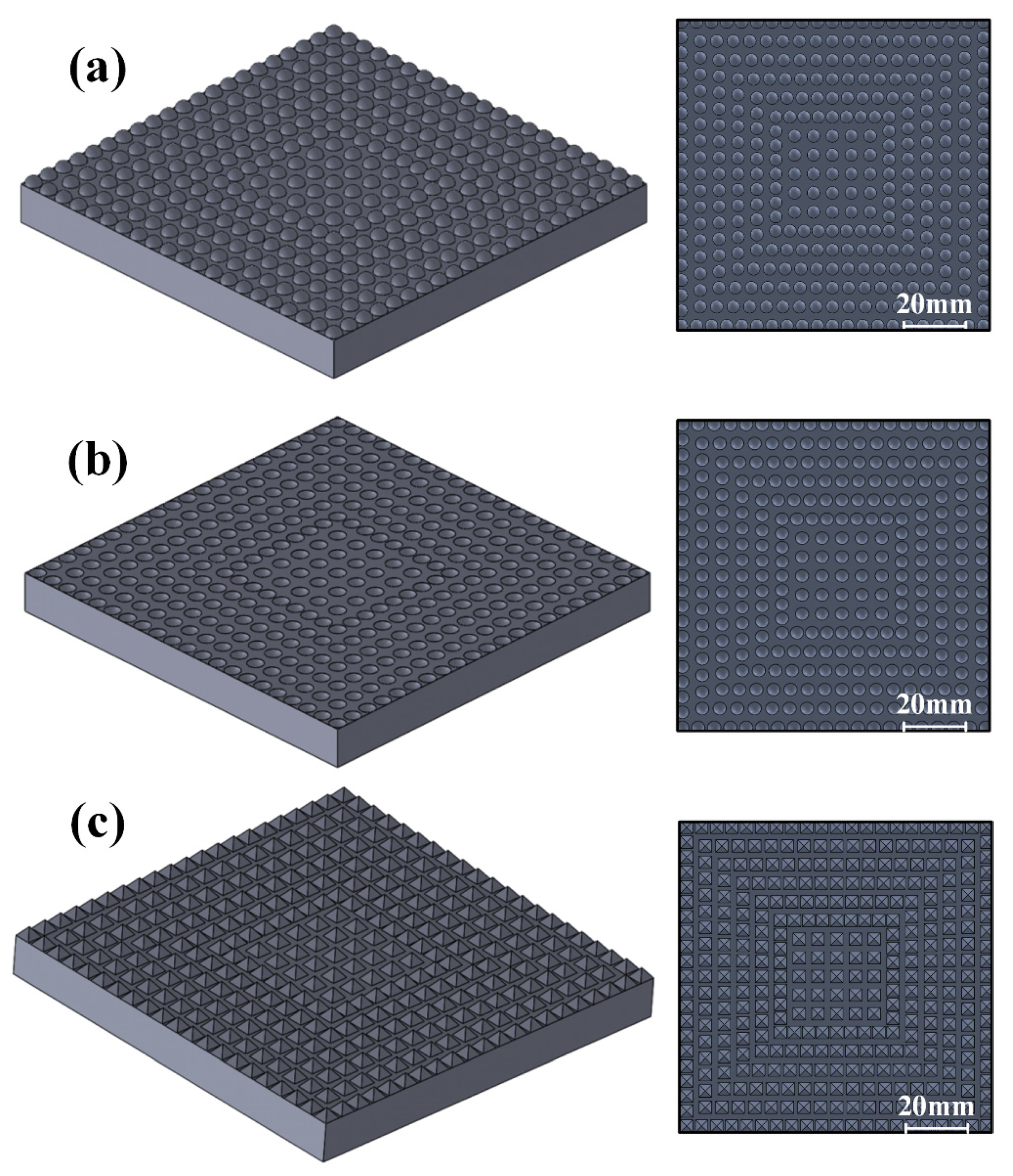
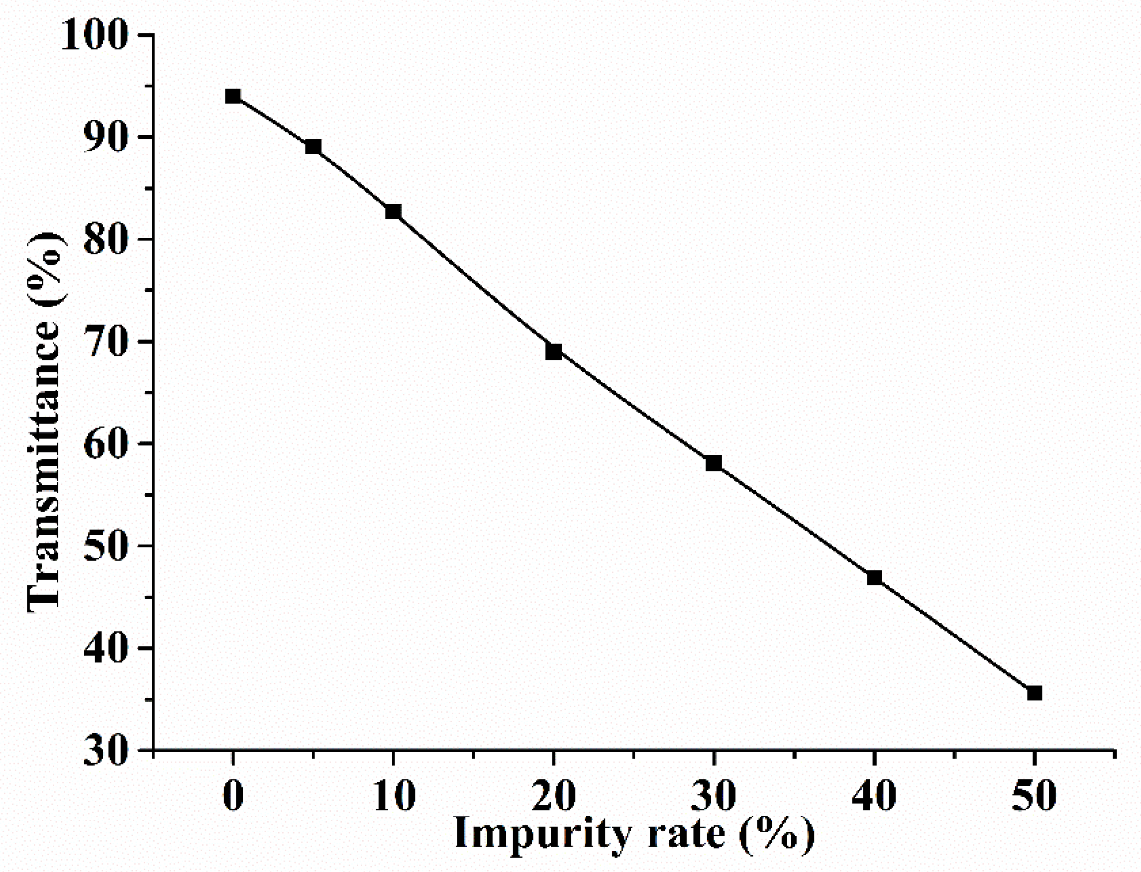
3.1. Simulation Modeling of Ice Influence

The ice layer that develops in cold chain transportation absorbs and scatters UVC light. To explore the influences of ice on the transmittance of UVC light, comparative simulation experiments were carried out with TracePro, which is a set of ray simulation software widely used in lighting systems, optical analysis, radiance analysis, and photometric analysis. In the experiments, 275 nm UVC was selected as the light source used to irradiate various ice layers, and the residual energy on the 150 × 150 mm surface of the lighting area was calculated. In addition, because the surface of ice is often not ideally flat, to explore the influence of the structure of the ice surface in the simulation, the complex ice surface was simplified into three regular surfaces (convex spherical, concave spherical, and conical), as shown in Figure 1a–c. The results of simulations on ice influence will be introduced in Section 4.1.

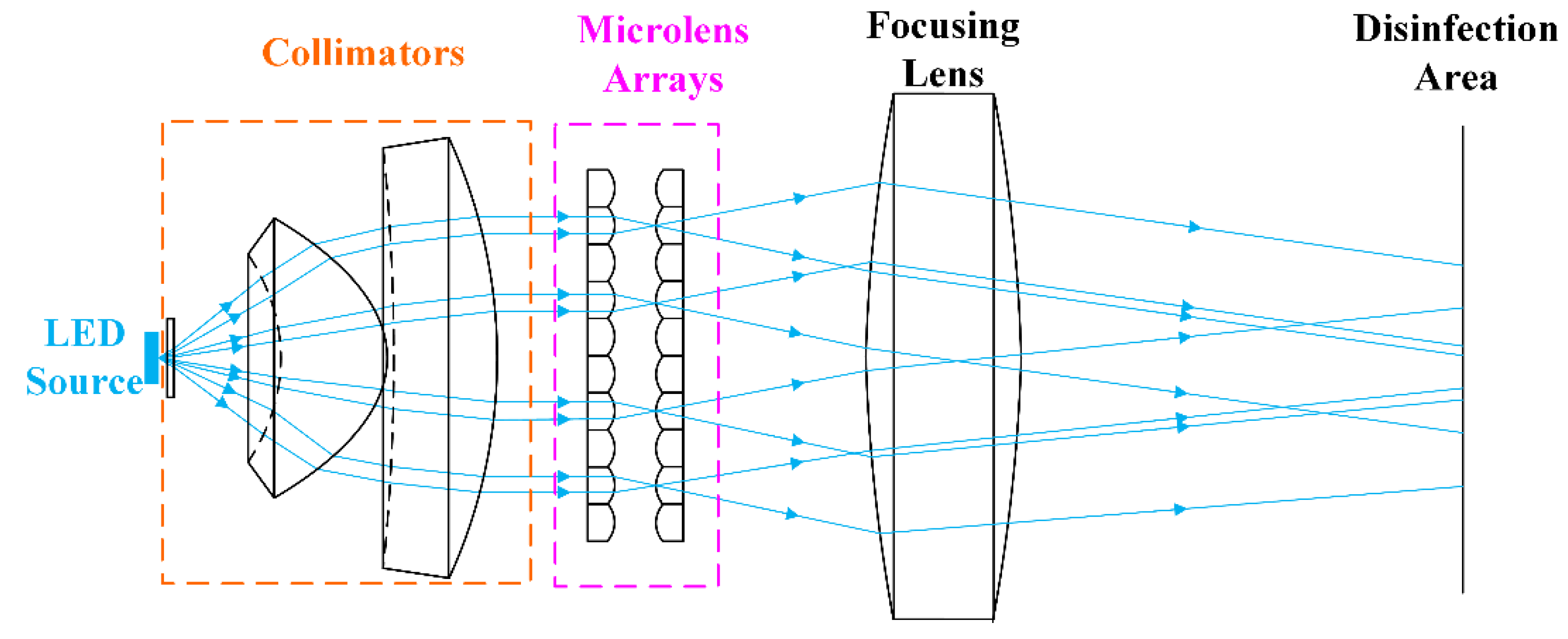
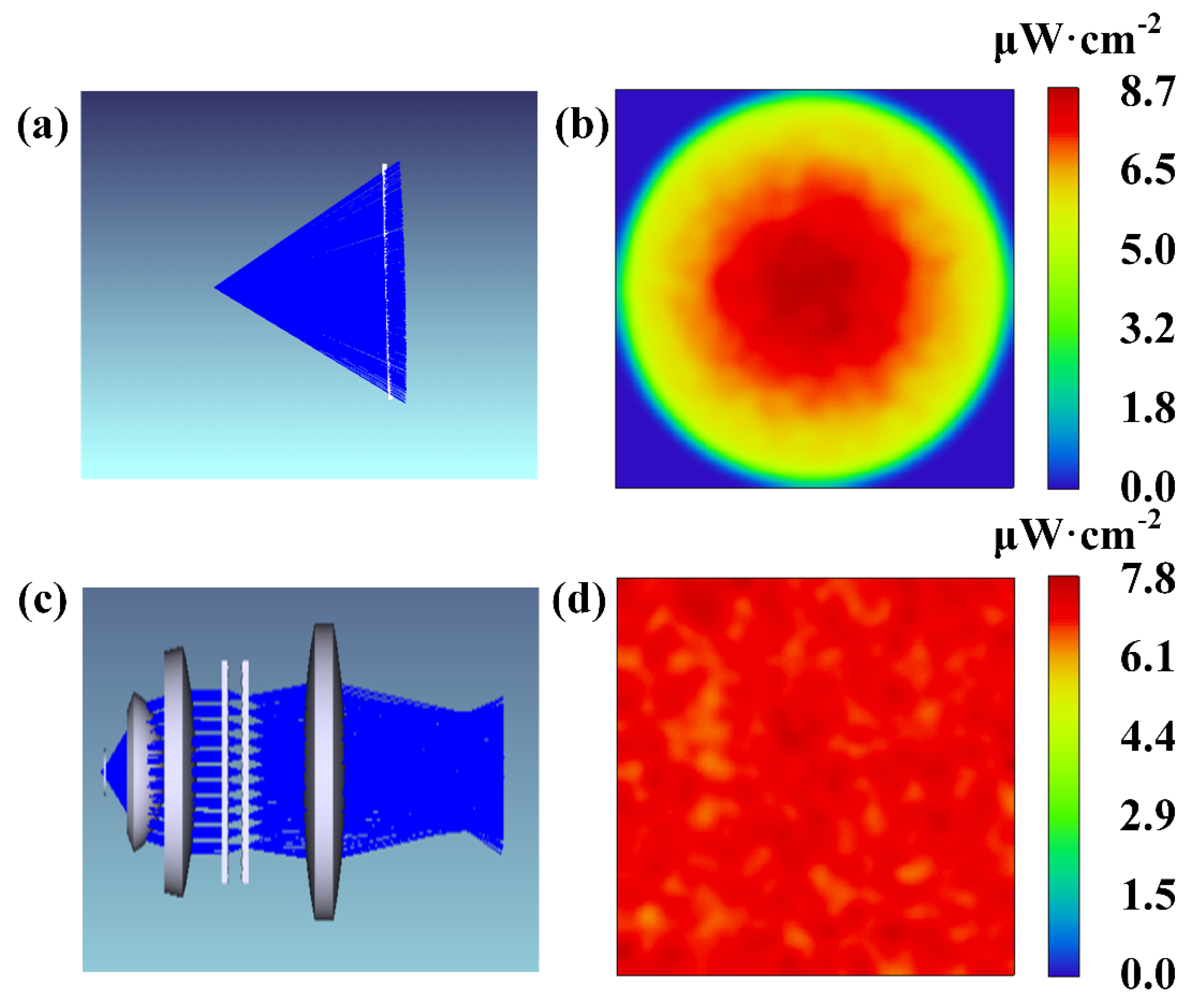
3.2. Design of the Proposed Optical System

Figure 2 presents the schematic diagram of the proposed system, in which a UVC-LED chip with a wavelength of 275 nm was used as the light source. Three collimating lenses (lens 1–3 in the Table 1) were used to realize the collimation of LED light, then a pair of microlens arrays (lens 4) and a focusing lens (lens 5) were used to regulate the uniformity of the light beam, thereby ensuring that the UVC light can realize the disinfection effect of the ice layer in cold chain transportation. The parameters of lenses are listed in Table 1. The proposed system provides an effective solution to stop the spread of global viral epidemics via disinfection during cold chain transportation.
The luminance of LEDs is defined as the amount of luminous flux emitted by the unit area of the light source surface in the unit solid angle of the normal direction, which is expressed as:
L = d ϕ d S cos θ d Ω
The luminous intensity of the light source is expressed as the luminous flux emitted within a unit solid angle, namely:
I = d ϕ d Ω
Therefore, the light distribution curve for a Lambert type LED light source can be expressed as follows [26]:
I ( θ ) = I 0 cos m θ
where, θ is the included angle between the luminous direction of the light source and the plane normal, and I0 is the intensity value of the normal direction. The value of m is generally provided by the LED manufacturer, and the ideal m value of an LED light source is 1.
Light field regulation is a method to control light field by using optical devices such as microlens arrays and a cylindrical mirror. It is widely used in lighting systems in recent years. LEDs are optically designed twice before they become lighting products to realize light field regulation [27,28]. According to the LED light distribution curve, when the light source is directly used for illumination, uneven light spots will be formed on the receiving surface. The light distribution curve of a Lambert-type LED is a cosine distribution, so the effect of strong lighting in the middle and low lighting at the edge will occur, and the LED will have a large divergence angle.
In current disinfection systems, a multi-chip or multi-device combination is carried out to achieve the uniformity of the lighting surface. However, the light field formed in this way is unable to meet the requirements of the uniformity of illumination in the entire illuminated area. Therefore, in the proposed system, the uniformity of the LED collimated beam is accomplished by using microlens arrays in conjunction with a focusing lens.
The essence of light uniformity is to transform the uneven lighting surface in the spatial domain into a uniform lighting surface. After homogenizing the illumination surface of a Lambert beam, the light intensity of the central area can be reduced and that of the edge area can be increased to improve energy utilization. To achieve this, the following principles must be met [29]:
Consider the radius of the LED circular spot after collimation as b, and the spot is divided into M uniform parts along the radial direction of the light. Then, the total power contained in the N-th uniform area is:
P ( N ) = 0 N M b I 0 cos m θ 2 π r d r
The power of the N-th annular region is:
{ P N = P ( N , z ) P ( N 1 , z ) = π c 2 { exp [ 2 2 u ( N 1 ) 2 M 2 ] exp ( 2 u N 2 M 2 ) } u = b 2 / w 2
Assuming that the illuminated area is a rectangular area and the length-width ratio of the rectangular area is β, the following can be obtained:
{ P N ( X N Y N X N 1 Y N 1 ) = P 1 X 1 Y 1 X N Y N = β
These equations can be combined to obtain the following:
{ Y N = { exp [ 2 u ( N 1 ) 2 M 2 ] exp ( 2 u N 2 M 2 ) } X 1 Y 1 1 exp ( 2 u M 2 ) + X N 1 Y N 1 / w X N = Y N β
From these equations, it can be seen that when the illumination intensity of the illumination surface is uniform, there is a corresponding relationship between the coordinates of the Lambert beam and the position coordinates of the illumination surface; the size and shape of the spot after the achievement of uniform light is determined by the area of the first equal projection rectangle. The parameters of microlens arrays can be calculated by the equations, as shown in Table 1. The optical simulation of the designed system will be carried out in Section 4.2.

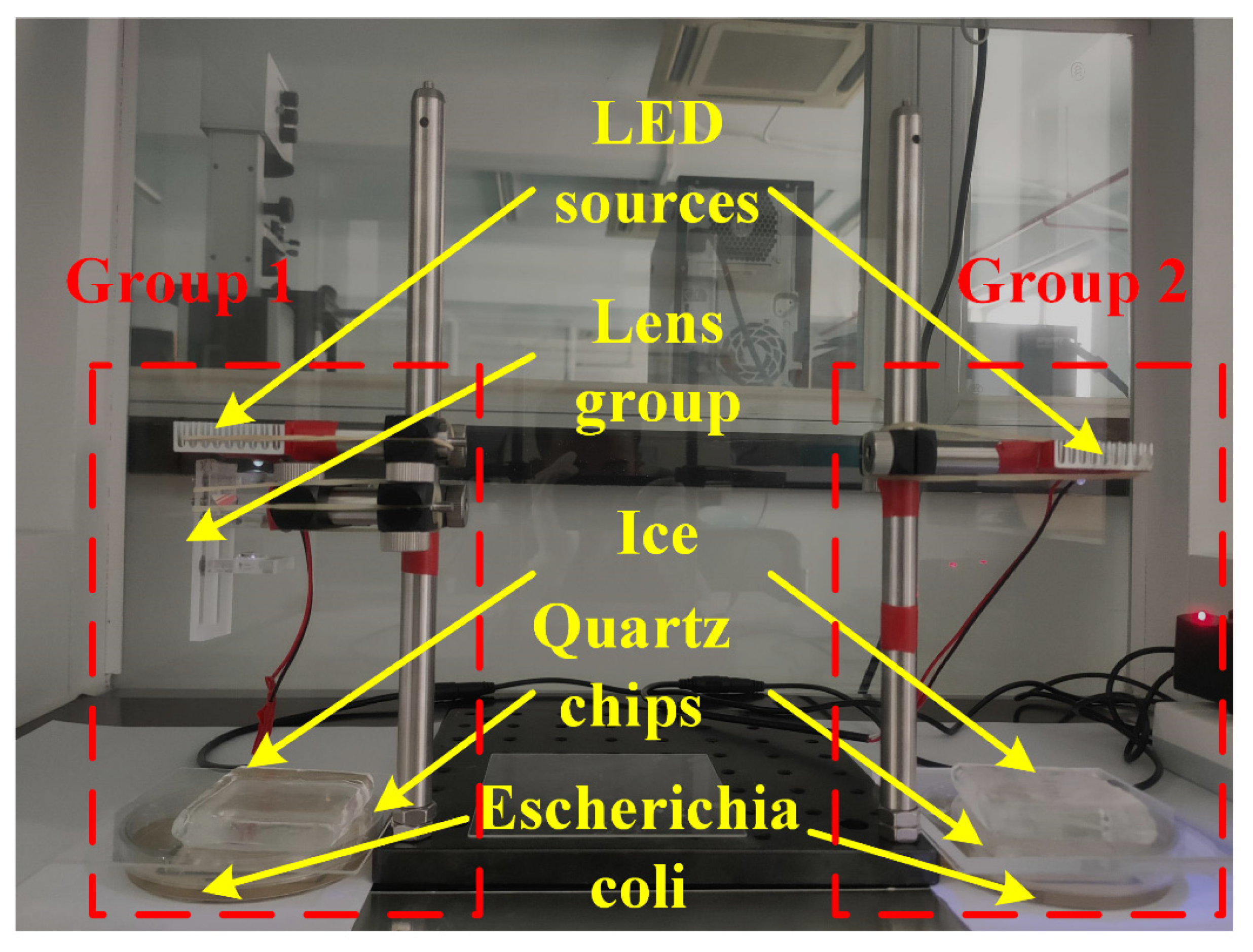
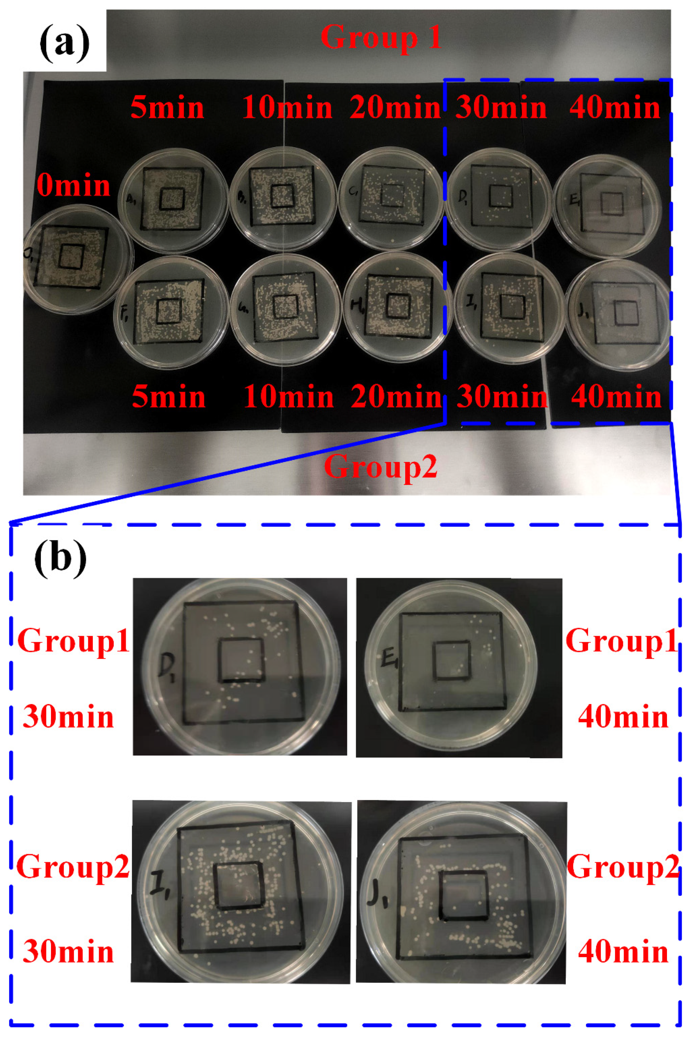
3.3. The Preparation of the Experiments

In order to verify the disinfection effect of the designed optical system, a comparative experiment was conducted. Before the experiment, the following conditions were prepared. All the steps were completed in the super-clean platform, and high quality, appropriate concentration of E. coli was cultured in advance. Before culturing E. coli, all the experimental supplies (tube, beaker, pipette et al.) that would be used later were put on the super-clean platform, with UV light shining for 15 min to create a sterile environment. Then, we removed E. coli (ATCC25922 standard strain) from the refrigerator, disinfected the surface of the glass tube with 75% alcohol, and opened the test tube in the super-clean platform. We took an appropriate amount of E. coli using the inoculation ring, put it into the petri dish 1, and put the petri dish 1 at 37 °C with constant temperature incubator for 24 h. Until this step, the initial recovery of E. coli was completed, and then it could be diluted appropriately as needed. For convenience of counting, the E. coli was washed twice with sterile saline solution (0.9% NaCl) by centrifugation. After 24 h culturing, we used the inoculation ring to place an appropriate amount of E. coli from petri dish 1 into sterile saline solution 1 (0.9% NaCl, 5 mL), and shake it well; concentration was approximately 106 CFU/mL. Then, we used a pipette to add 10 μL of E. coli solution to sterile saline solution 2 (0.9% NaCl, 10 mL), obtaining a concentration of approximately 1191 CFU/mL. We took an appropriate amount of E. coli using the pipette, put it into the Petri dishes, and put them at 37 °C with the constant temperature incubator for 24 h. At this point, high quality and appropriate concentration of E. coli was cultured successfully.
During the experiment, firstly, two sets of optical systems, namely Group 1 and Group 2 were constructed, as shown in Figure 3. Both groups used a UVC-LED (2 mW, 275 nm, chosen from Shenzhen Silverlight Technologies Co. Ltd. (Shenzhen, China), 3535-UVC-270-280NM-IF40MA-60°) as a light source, with an installation height of about 150 mm. Group 1 had the uniform light path using the lens group described in this paper, and the ice block (60 × 60 mm) with a thickness of 30 mm and a flat surface was placed on the path of light, the transmittance of which was greater than 90%. At the bottom was the E. coli and a piece of quartz chip, the function of which was to avoid the melted ice. In the experiment, it should be noted that it was necessary to maintain observation at all times and replace the melted ice in time. Group 2 contained only one LED light source as the control, and other installation conditions were consistent with Group 1. In addition, Group 2 also included quartz chips to imitate the attenuation effect of the lens group on the light in Group 1. The results of experiments will be introduced in Section 4.3.

4. Results

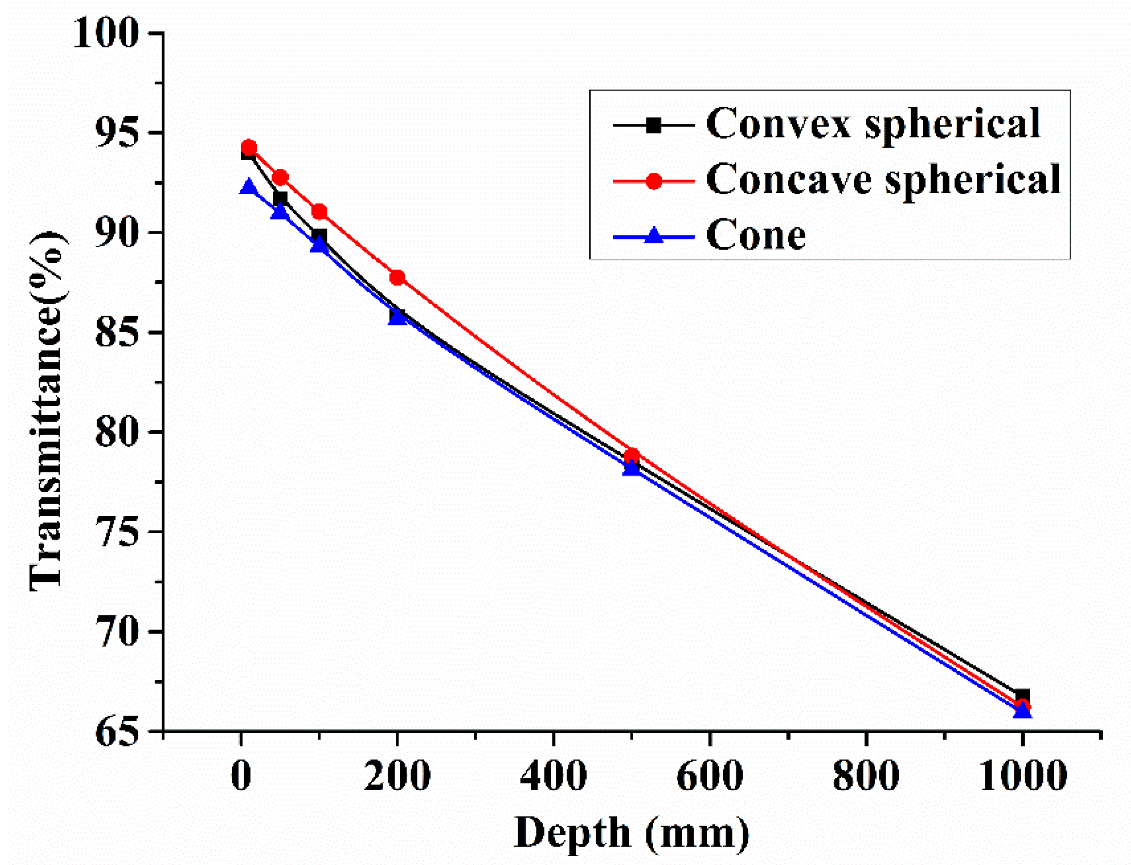
4.1. Results of Simulations on Ice Influence

These three types of ice surfaces with different thicknesses (10, 50, 100, 200, 500, and 1000 mm) are contrasted under the influence of UVC beam transmittance, and the result curve is presented in Figure 4. It can be concluded from the figure that when the ice thickness was small (less than 500 mm), the ice surface structures had substantially different influences on the transmittance of the UVC beams; the concave spherical surface was found to have the least influence, while the conical surface was found to have the greatest influence. When the thickness of the ice was greater than 500 mm, the effect of the ice surface structure on the transmittance of the UVC beam was not significant. Due to the absorption of UVC beams by the ice layer, the thicker the ice layer, the higher was the UVC light energy absorbed by the ice layer, perhaps reducing the UVC disinfection effect. As can be seen from the figure, when the thickness of the ice reached about 50 mm, the absorption rate of the light beam was found to be close to 10% for all three surface morphologies of pure ice.
To investigate the influence of the ice impurity rate on the UVC transmittance, a 10 mm thick convex spherical ice surface with impurity ratios of 5%, 10%, 20%, 30%, 40% and 50% was taken as an example to simulate the transmittance of light beams, and the result is shown in Figure 5; here the impurity rate is defined as the proportion of opaque part in the whole ice. And it is evident that the presence of impurities affected the transmittance of the beam in the ice. When the impurity rate was 5%, the UVC beam absorption rate of the ice reached about 10%. Combined with the effect of the thickness of the ice itself, this reduces the efficiency of UVC disinfection.
Besides the influences from the thickness, surface structure and impurity rate of the ice, there are many other factors that affect the UVC transmittance, and this work only explored the three factors above. Based on the results of a series of comparative simulations, it is evident that the thickness, surface structure and impurity rate of the ice greatly affect the UVC transmittance efficiency, and the higher the UVC transmittance is, the more energy will be saved. Therefore, traditional UVC disinfection methods face great challenges, and effective solutions are urgently required.

4.2. Simulation of the Proposed Optical System

In this proposed system, a pair of microlens arrays and a piece of focusing lens were designed and used as the uniformity elements to achieve a compact structure and uniform illumination. To get uniformity on the same plane, the full width of the light surface must be illuminated by equal axial and divergent rays. By achieving uniformity via the microlens arrays and focusing lens, the power loss of luminance caused by the uneven distribution of luminance in the illumination plane is reduced, and a uniform illumination spot is obtained.
The effect of ordinary UVC-LED illumination was compared with the effect of uniform UVC-LED illumination based on microlens arrays. Figure 6a presents the light distribution of a single LED chip, and Figure 6b exhibits the light distribution effect, which reveals high brightness in the center (8.7 μW·cm−2), surrounded by low brightness (1.8 μW·cm−2). The central part with higher luminance is characterized by energy waste, while the surrounding part has the risk of substandard luminance. Figure 6c presents the uniform lighting effect of the UVC-LED based on microlens arrays designed in this paper.
The illumination intensity of the illuminated surface is calculated as follows:
γ = 1 | E i E ¯ | n E ¯
where n is the number of sampling points, Ei is the illumination intensity of the sampling points, and E is the average illumination intensity of the sampling points.
Compared with that shown in Figure 6b, a better lighting effect was achieved. In addition, the illumination uniformity shown in Figure 6d is 96.4%, and the luminance of the central part of the illuminated area (7.8 μW·cm−2) is not much different from that of the surrounding area (1.5 μW·cm−2). From the results of simulation, we can see that the proposed system can improve the illumination uniformity while ensuring the using requirements, which is consistent with our design. In the proposed system, the light field is regulated as we design, with less light in the center area and more light in the edge area; therefore, the energy is uniform in the whole area and reduces the risk of excessive disinfection and incomplete disinfection, ensuring the disinfection quality.

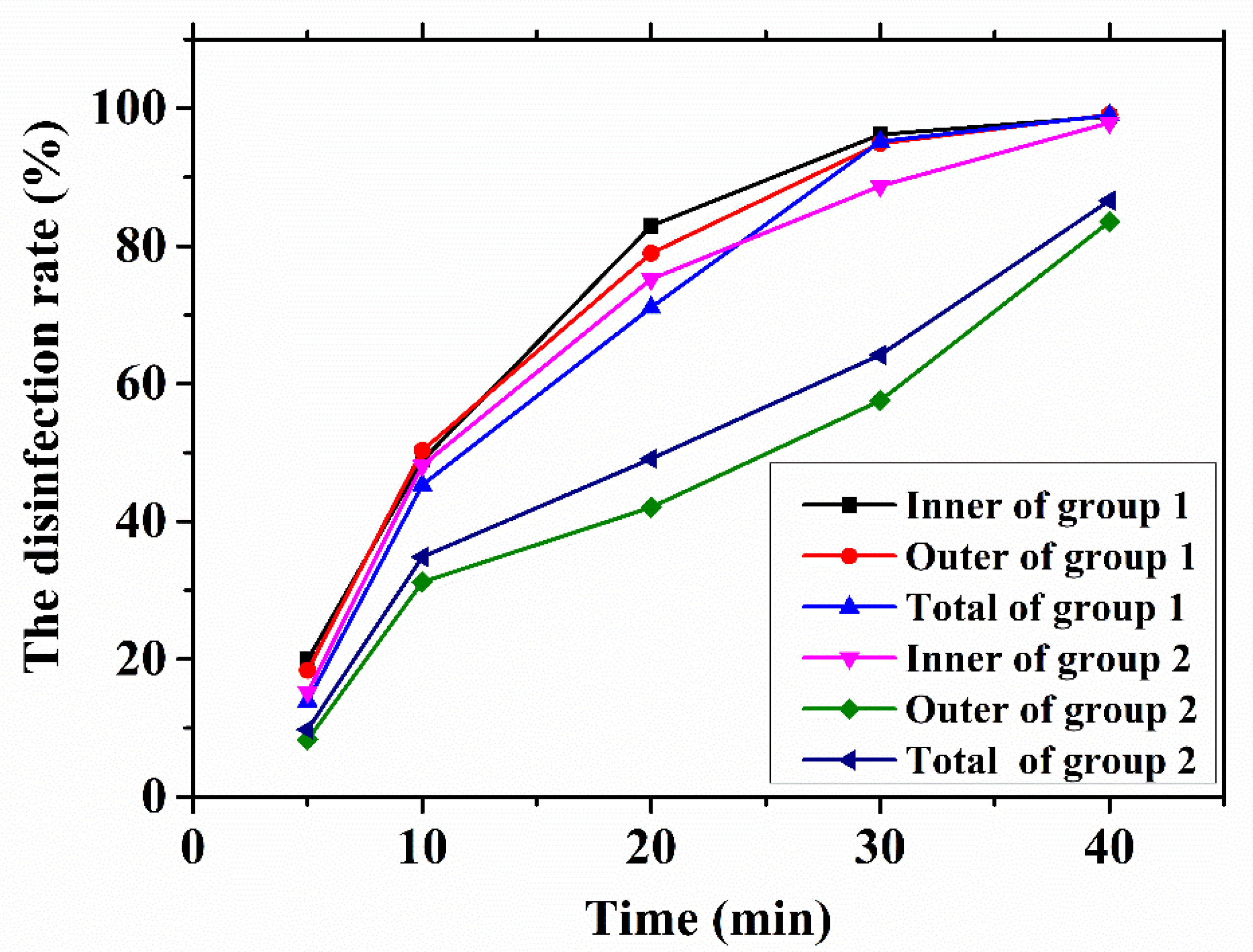
4.3. Results of Experiments

The experiments were conducted to investigate the effect of the disinfection of E. coli through ice (30 mm) in two groups for different periods (5, 10, 20, 30, and 40 min). Each group after irradiation was put into the constant temperature incubator for 24 h at 37 °C. To avoid accidental errors, the experiment was conducted 3 times for each period, and the average value was taken as the result. Each Petri dish contained two square frames with side lengths of 50 and 20 mm, and the number of colonies in the two frames was counted to conduct the analysis of the results, the purpose of which was to compare the effect of uniform light on the disinfection effect. The final disinfection effect is shown in Figure 7a; the leftmost is the reference group, that is, the E. coli after 0 min of irradiation. Group 1 is above, while Group 2 is below; from left to right are the results of different periods (5, 10, 20, 30, and 40 min) of irradiation in each group. The white dot in the figure is the E. coli colony, the number of which is the indicator of disinfection effect. It can be seen that the number of E. coli colony in both groups decreased rapidly. However, the speed of decreasing differed in two groups, including the speed of decreasing in inner frame and outer frame in the same group. Note the disinfection results of two groups after 30 min and 40 min, for example, as shown in Figure 7b. Firstly, in the comparison between up and down, the number of E. coli colony in Group 1 was significantly less than that of Group 2 in the same period, and there were few E. coli in Group 1 after 30 min, while there were still many in Group 2 after 40 min. Then, in the comparison of inner frame and outer frame in the same group, it can be seen that the decreasing speed is almost the same of inner frame and out frame in Group 1, while this differs a lot in Group 2. For quantitative comparison, the average results of each group are listed in Table 2.
According to the parameters in the table, the disinfection rate (%) of each period can be obtained by the following formula:
α = N 0 N t N 0
where α is the disinfection rate, N0 is the number of E. coli in the non-irradiation group (0 min), and Nt is the number of E. coli after t minutes of irradiation. Then the disinfection rate of each group can be calculated, as shown in Table 3, and Figure 8 can be drawn according to Table 3 at the same time.
Based on Figure 8, firstly, comparing the curve “Inner of Group 1” and “Outer of Group 1”, it can be seen that the changes in the disinfection rates of the inner and the outer frames of Group 1 for different periods were almost the same, which proves the uniform effect of the designed system. Then, comparing the curve of “Inner of Group 2” and “Outer of Group 2”, the disinfection rates of the inner and the outer frames of Group 2 differed greatly with time; this is due to the uneven UVC light energy between the inner frame and the outer frame of Group 2. Thirdly, comparing the curve of “Inner of Group 1” and “Inner of Group 2”, it can be seen that the disinfection rates of the inner frame in both groups were close, which indicates that the light field regulation of UVC-LED will not reduce the energy in the central area. In addition, by comparing the curve of “Outer of Group 1” and “Outer of Group 2”, it can be seen that the disinfection effect of the outer frame of Group 2 was bad, which further confirms that UVC-LED needs light field regulation to solve the problem of low energy in the surrounding area. Finally, by comparing the total disinfection rates of Groups 1 and 2, it can be seen that the disinfection effect of Group 1 was significantly better than that of Group 2. The disinfection rate of Group 1 in 30 min was close to 100% with a dose of 7.92 mJ·cm−2, while that of Group 2 in 40 min was less than 90%. While the disinfection rate of the inner frame was comparable to that of Group 1, that of the outer frame was much lower, less than 80% at 40 min. In conclusion, the disinfection efficiency can be increased nearly by 30% with the proposed system. (It is worth noting that the power of the UVC-LED used in this experiment is not high, resulting in a complete disinfection time of nearly 30 min. In practical application, the power of the UVC-LED can be appropriately increased to improve the disinfection efficiency.).
The results of experiments verify the feasibility of the design again, and match the results of simulation in Section 4.2 as well. With the proposed system, the disinfection efficiency can be improved by nearly 30%, which means energy saving and efficiency improvement, and plays a positive role in the disinfection methods in cold chain transportation.

5. Discussion

Via comparison from Section 4, it can be seen that the proposed microlens arrays UVC-LED disinfection system achieves light field regulation, which can greatly improve the energy utilization rate and ensure UVC light realizes the disinfection effect of goods under ice in cold chain transportation.
On the premise of the wide application of UVC for disinfection, aiming at the disinfection demands in cold chain transportation and facing the difficulties caused by ice layer and transportation environment, this paper proposes a uniform UVC light disinfection system, which combines light regulation, optical design and a disinfection system, in order to improve disinfection efficiency, overcome a challenging environment and save energy, providing reliable help for disinfection in cold chain transportation. An additional benefit from the light field regulation of UVC-LED disinfection is that the uniform lighting helps reduce the dose of UVC to 7.92 mJ·cm−2 compared to the dose of about 1048 mJ·cm−2 in other research, which may help to save a great deal of energy when this technology is widely used. Moreover, the disinfection efficiency can be increased nearly by 30% with the proposed system, achieving a huge increase in efficiency. In conclusion, the results match the initial hypothesis.

6. Conclusions

This paper aimed at improving the disinfection efficiency in cold chain transportation. Firstly, the influences of ice on UVC disinfection were explored. Then, a uniform UVC light disinfection system for cold chain transportation was designed, the uniform light rate of which reached 96.4%. Finally, a comparative experiment was conducted, and the results verify that the disinfection efficiency can be increased nearly by 30% with the proposed system, which provides an effective solution during cold chain transportation, with great practical application prospects. However, limitations still exist in our research, such as the limited lighting area and high cost of microlens arrays. Therefore, our future potential research may focus on solving the problem of the limited lighting area and reducing the cost of microlens arrays. We share hope that it will help in the cold chain transportation disinfection field.

Author Contributions

Conceptualization, Z.G. and P.L.; methodology, Z.G. and P.L.; software, Z.G.; validation, T.Z., L.Z., X.W. and W.Z.; formal analysis, Q.Y.; investigation, D.Z.; resources, Q.X.; data curation, Y.H.; writing—original draft preparation, Z.G. and P.L.; writing—review and editing, T.Z.; visualization, S.W.; supervision, P.L. and L.Z.; project administration, T.Z.; funding acquisition, T.Z. and P.L. All authors have read and agreed to the published version of the manuscript.

Funding

This work was supported by the National Natural Science Foundation of China (52005040, 51775046, 51875043), the Beijing Municipal Natural Science Foundation (JQ20014), the China Postdoctoral Science Foundation (2019M660480), and the Natural Science Foundation of Chongqing of China (cstc2020jcyj-msxmX0884, cstc2020jcyj-msxmX0601).

Institutional Review Board Statement

Not applicable.

Informed Consent Statement

Not applicable.

Data Availability Statement

Not applicable.

Conflicts of Interest

The authors declare no conflict of interest.

Abbreviation

AbbreviationDetailed meaning
UVCUltraviolet C
LEDLight Emitting Diode
E. coliEscherichia coli
COVID-19Corona Virus Disease 2019
CAPCold atmospheric plasma
DUVDeep-Ultraviolet
LP-UVLow-pressure mercury UV
TCID5050% Tissue culture infectivedose

References

  1. Pang, X.; Ren, L.; Wu, S.; Ma, W.; Yang, J.; Di, L.; Li, J.; Xiao, Y.; Kang, L.; Du, S.; et al. Cold-chain food contamination as the possible origin of COVID-19 resurgence in Beijing. Natl. Sci. Rev. 2020, 7, 1861–1864. [Google Scholar] [CrossRef] [PubMed]
  2. Zhang, X. COVID-19 transmission in cold chain: A safe and green new-generation cold chain is demanded. Int. J. Energy Res. 2021, 45, 6483–6488. [Google Scholar] [CrossRef]
  3. Van Doremalen, N.; Bushmaker, T.; Morris, D.; Holbrook, M.; Gamble, A.; Williamson, B.; Tamin, A.; Harcourt, J.; Thornburg, N.; Gerber, S.; et al. Aerosol and surface stability of SARS-CoV-2 as compared with SARS-CoV-1. N. Engl. J. Med. 2020, 382, 1564–1567. [Google Scholar] [CrossRef] [PubMed]
  4. Chan, K.; Marlik Peiris, J.; Lam, S.; Poon, N.; Yuen, K.; Seto, W. The effects of temperature and relative humidity on the viability of the SARS coronavirus. Adv. Virol. 2011, 2011, 734690. [Google Scholar] [CrossRef] [PubMed]
  5. Chen, Z.; Garcia, G.; Arumugaswami, V.; Wirz, R. Cold atmospheric plasma for SARS-CoV-2 inactivation. Phys. Fluids 2020, 32, 111702. [Google Scholar] [CrossRef]
  6. Zhang, H.; Chen, M.; Huang, L.; Guo, L.; Xu, S.; Zhang, J.; Xi, W.; Wang, Z.; Liu, D.; Kong, M. Using cold atmospheric plasma treated-air for COVID-19 disinfection in cold-chain environment. J. Phys. D Appl. Phys. 2021, 54, 40LT01. [Google Scholar] [CrossRef]
  7. Koutchma, T. Advances in ultraviolet light technology for non-thermal processing of liquid foods. Food Bioprocess Technol. 2009, 2, 138–155. [Google Scholar] [CrossRef]
  8. Zeqiri, B.; Hodnett, M.; Carroll, A. Studies of a novel sensor for assessing the spatial distribution of cavitation activity within ultrasonic cleaning vessels. Ultrasonics 2006, 44, 73–82. [Google Scholar] [CrossRef]
  9. Shin, J.; Kim, S.; Kim, D.; Kang, D. Fundamental characteristics of deep-UV light-emitting diodes and their application to control foodborne pathogens. Appl. Environ. Microbiol. 2016, 82, 2–10. [Google Scholar] [CrossRef] [Green Version]
  10. Liang, J.; Liao, C.; Chang, C.; Lee, C.; Chen, S.; Huang, S.; Yeh, Y.; Singh, K.; Kuo, H.; Lin, Y.; et al. The Effectiveness of far-ultraviolet (UVC) light prototype devices with different wavelengths on disinfecting SARS-CoV-2. Appl. Sci. 2021, 11, 10661. [Google Scholar] [CrossRef]
  11. Heilinglog, C.; Aufderhorst, U.; Schipper, L.; Dittmer, U.; Witzke, O.; Yang, D.; Zhang, X.; Sutter, K.; Trilling, M.; Alt, M.; et al. Susceptibility of SARS-CoV-2 to UV irradiation. Am. J. Infect. Control 2020, 48, 1273–1275. [Google Scholar] [CrossRef] [PubMed]
  12. Kitagawa, H.; Nomura, T.; Nazmul, T.; Keitaro, O.; Shigemoto, N.; Sakaguchi, T.; Ohge, H. Effectiveness of 222-nm ultraviolet light in disinfection SARS-CoV-2 surface contamination. Am. J. Infect. Control 2020, 49, 299–301. [Google Scholar] [CrossRef] [PubMed]
  13. Liang, S.; Hao, R.; Fan, D.; Li, B.; Huang, J.; Zhang, Y.; Wu, J.; Li, Y.; Mo, J. Structural optimization and numerical thermal analysis of ultraviolet light-emitting diodes with high-power multi-chip arrays. Optik 2020, 222, 165333. [Google Scholar] [CrossRef]
  14. Buonanno, M.; Welch, D.; Shuryak, I.; Brenner, D. Far-UVC light (222 nm) efficiently and safely inactivates airborne human coronaviruses. Sci. Rep. 2020, 10, 10285. [Google Scholar] [CrossRef] [PubMed]
  15. Chawla, A.; Lobacz, A.; Tarapata, J.; Zulewska, J. UV light application as a mean for disinfection applied in the dairy industry. Appl. Sci. 2021, 11, 7285. [Google Scholar] [CrossRef]
  16. Bačík, J.; Tkáč, P.; Hric, L.; Alexovič, S.; Kyslan, K.; Olexa, R.; Perduková, D. Phollower—The universal autonomous mobile robot for industry and civil environments with COVID-19 germicide addon meeting safety requirements. Appl. Sci. 2020, 10, 7682. [Google Scholar] [CrossRef]
  17. Shen, L.; Grilffith, T.; Nyangaresi, P.; Qin, Y.; Pang, X.; Chen, G.; Li, M.; Lu, Y.; Zhang, B. Efficacy of UVC-LED in water disinfection on Bacillus species with consideration of antibiotic resistance issue. J. Hazard. Mater. 2020, 386, 121968. [Google Scholar] [CrossRef]
  18. Shatalov, M.; Sun, W.; Jain, R.; Lunev, A.; Hu, X.; Dobrinsky, A.; Bilenko, Y.; Yang, J.; Garrett, G.; Rodak, L.; et al. High power AlGaN ultraviolet light emitters. Semicond. Sci. Technol. 2014, 29, 084007. [Google Scholar] [CrossRef]
  19. Shur, M.; Gaska, R. Deep-ultraviolet light-emitting diodes. IEEE Trans. Electron Devices 2010, 57, 12–25. [Google Scholar] [CrossRef]
  20. Tamulaitis, G. Ultraviolet light emitting diodes. Lith. J. Phys. 2011, 51, 177–193. [Google Scholar] [CrossRef] [Green Version]
  21. Muramoto, Y.; Kimura, M.; Nouda, S. Development and future of ultraviolet light-emitting diodes: UV-LED will replace the UV lamp. Semicond. Sci. Technol. 2014, 29, 084004. [Google Scholar] [CrossRef] [Green Version]
  22. Djavid, M.; Mi, Z. Enhancing the light extraction efficiency of AlGaN deep ultraviolet light emitting diodes by using nanowire structures. Appl. Phys. Lett. 2016, 108, 051102. [Google Scholar] [CrossRef]
  23. Ryu, H.; Choi, I.; Choi, H.; Shim, J. Investigation of light extraction efficiency in AlGaN deep ultraviolet light-emitting diodes. Appl. Phys. Express 2013, 6, 062101. [Google Scholar] [CrossRef]
  24. Adivarahan, V.; Sun, W.; Chitnis, A.; Shatalov, M.; Wu, S.; Maruska, H.; Khan, M. 250 nm AlGaN light-emitting diodes. Appl. Phys. Lett. 2004, 85, 2175–2177. [Google Scholar] [CrossRef]
  25. Wu, S.; Adivarahan, V.; Shatalov, M.; Chitnis, A.; Sun, W.; Khan, M. Micro-pixel design milliwatt power 254 nm emission light emitting diodes. Jpn. J. Appl. Phys. 2004, 43, 8–11. [Google Scholar] [CrossRef]
  26. Zhen, Z.; Xiang, H.; Xu, L. Freeform surface lens for LED uniform illumination. Appl. Optics 2009, 48, 6627–6634. [Google Scholar]
  27. Ding, Y.; Liu, X.; Zheng, Z.; Gu, P. Secondary optical design for LED illumination using freeform lens. Illum. Opt. 2008, 7103, 71030K. [Google Scholar]
  28. Tai, W.; Schwarte, R. Design of an aspherical lens to generate a homogenous irradiance for three-dimensional sensors with a light-emitting-diode source. Appl. Opt. 2000, 39, 5801. [Google Scholar] [CrossRef]
  29. Liu, P.; Guan, Z.; Zhou, T.; Xie, Q.; Yu, Q.; He, Y.; Zeng, Z.; Wang, X. Laser regulation for variable color temperature lighting with low energy consumption by microlens arrays. Appl. Opt. 2021, 60, 5652–5661. [Google Scholar] [CrossRef]
Figure 1. (a) Ice with a convex spherical surface; (b) ice with a concave spherical surface; (c) ice with a conical surface.
Applsci 12 01285 g001
Figure 2. The schematic diagram of the proposed uniform UVC-LED disinfection system by microlens arrays.
Applsci 12 01285 g002
Figure 3. Ultraviolet-C (UVC) disinfection systems, Group 1 (left) and Group 2 (right).
Applsci 12 01285 g003
Figure 4. The relationship between ice transmittance and ice thickness.
Applsci 12 01285 g004
Figure 5. The relationship between ice transmittance and the impurity rate.
Applsci 12 01285 g005
Figure 6. (a) The light distribution of a single LED chip; (b) the illuminance diagram of a single LED; (c) the light distribution of the proposed LED microlens arrays; (d) the illuminance diagram of the microlens arrays.
Applsci 12 01285 g006
Figure 7. (a) The disinfection results of two groups for different periods; (b) the detailed disinfection results of two groups after 30 and 40 min.
Applsci 12 01285 g007
Figure 8. The relationship between the disinfection rate and period in different areas for the two systems.
Applsci 12 01285 g008
Table 1. The parameters of lenses (unit: mm, material: silica).
LensLens 1Lens 2Lens 3Lens 4Lens 5
TypeStandard LensStandard LensStandard LensMicrolens ArrayStandard Lens
X Half-Width///0.5/
Y Half-Width///0.5/
Clear 11.534.018.06/10.0
Clear 21.535.368.44/10.0
Thickness0.34.04.01.06.0
Radius 10−6.9−76.32−1.230.0
Conic 10000.50
Radius 20−5.5−20.00−30.0
Conic 200000
Table 2. The disinfection results of each group (CFU/mL).
TimesGroup 1 (in)Group 1 (out)Group 1 (Total)Group 2 (in)Group 2 (out)Group 2 (Total)
0 min254.00937.001191.00254.00937.001191.00
5 min203.33764.67968.00215.33859.001074.33
10 min127.33465.67593131.67644.67776.33
20 min43.33197.00240.3363.00543.00606.00
30 min9.6747.6757.3328.67397.67426.33
40 min3.009.0012.005.33154.33159.67
Table 3. The disinfection rates of each group (%).
TimesGroup 1 (in)Group 1 (out)Group 1 (Total)Group 2 (in)Group 2 (out)Group 2 (Total)
0 min//////
5 min19.9518.3918.7215.228.329.80
10 min49.8750.3050.2148.1631.2034.82
20 min82.9478.9879.8275.2042.0549.12
30 min96.1994.9195.1988.7157.5664.20
40 min98.8299.0498.9997.9083.5386.59
Publisher’s Note: MDPI stays neutral with regard to jurisdictional claims in published maps and institutional affiliations.

