
A Compact Self-Injection-Locked Narrow-Linewidth Diode Laser with Narrowband Dielectric Filter
by
 ,
,
Pengfei Fan
1,2,3,†,
Peng Xu
1,3,4,†,
Hua-Ying Liu
1,2,3,* ,
,
Minghao Shang
1,2,3,
Zhenda Xie
1,3,4 and
Shining Zhu
1,4 1
National Laboratory of Solid State Microstructures, Nanjing University, Nanjing 210093, China
2
School of Physics, Nanjing University, Nanjing 210093, China
3
School of Electronic Science and Engineering, Nanjing University, Nanjing 210093, China
4
School of Engineering and Applied Sciences, Nanjing University, Nanjing 210093, China
*
Author to whom correspondence should be addressed.
†
These authors contributed equally to this work.
Appl. Sci. 2023, 13(8), 4765; https://0-doi-org.brum.beds.ac.uk/10.3390/app13084765
Submission received: 28 February 2023
/
Revised: 27 March 2023
/
Accepted: 31 March 2023
/
Published: 10 April 2023
(This article belongs to the Collection Optical Design and Engineering)
Abstract
:The self-injection-locked diode laser can significantly reduce the linewidth down to a sub-100 kHz level but requires optical filtering that is much narrower than the laser cavity linewidth. Such optical filtering is usually sophisticated and beyond the capability of the normal dielectric coating approach. Here we develop a 0.16 nm narrowband dielectric coating using a Fabry–Perot dielectric filter (HFFPF) for the narrow linewidth self-injection-locked laser demonstration using a cost-effective Fabry–Perot laser diode. Single-longitude-mode output is achieved, with beat linewidth down to ~66 kHz and a high side mode suppression ratio over 60 dB. This setup of self-injection-locked laser is cost-effective for mass production and thus is suitable for various applications such as laser ranging, LIDAR, optical communication, and holographic.
Narrow-linewidth lasers with a sub-100 kHz linewidth play an important role in laser ranging [1], LIDAR [2], optical communication [3,4,5,6,7,8,9] and holographic applications [10]. Such narrow-linewidth lasers can be achieved by the self-injection locking of a diode laser to a narrowband filter [11,12,13,14,15,16], where the laser light is directed through the filter and fed back to the laser cavity. This narrowband filtering is normally achieved using diffraction grating [17], volume Bragg grating [18], or a high-Q resonator [19]. In comparison to the above filtering methods, dielectric filtering is more widely used for other optical applications [20] for its low cost in mass production and compact size. However, it is difficult to fabricate a dielectric filter with a bandwidth lower than 1 nm, which is comparable to or broader than the cold cavity bandwidth of a diode laser [21]. Therefore, the application is limited for the narrow-linewidth laser realization using the dielectric filters.
In this paper, we demonstrate a compact narrow-linewidth diode laser that is self-injection-locked to a dielectric-coated high-finesse Fabry–Pérot dielectric filter (HFFPF) with a beat linewidth of ~66 kHz. This HFFPF features in a narrow full-width half-maximum (FWHM) bandwidth of 0.16 nm and a large free spectrum range (FSR) of 11.2 nm. Taking advantage of the HFFPF, a single-longitudinal-mode lasering is achieved, with a high side-mode suppression ratio of over 60 dB. The key innovation is that besides the two high-reflection layers, the resonance cavity layer is also fabricated through the ion-assisted deposition method in the HFFPF; hence, the high reflectivity and thin resonance cavity thickness are achieved at the same time. In a single batch of coating, we fabricated a large number of HFFPFs that can be used for ~23,000 narrow-linewidth lasers, demonstrating its extraordinary mass production capability. Our result shows a new approach for narrow-linewidth laser fabrication with a low requirement for the laser diode (LD), thus reducing the system cost and enabling mass-production capability, which would push forward its practical application in the relevant fields.
For Fabry–Pérot laser diodes (FP-LD), the FSR is normally in the order of sub-nanometer, which is smaller than the semiconductor gain bandwidth. A free-running FP-LD is thus usually lasing in multi-longitudinal modes. Here, we choose to use a Fabry–Pérot (FP) cavity for the self-injection locking of an FP-LD, not only to narrow the laser linewidth but also to achieve single-longitudinal-mode lasing.
In an FP cavity [22], the transmission bandwidth is calculated by , where the F is the finesse of the FP cavity and the FSR is related to the cavity thickness t, by
where ng is the group refractive index of the resonance cavity layer, and c is the light speed. It is beneficial to have a large FSR and a small bandwidth for the self-injection locking laser based on the FP cavity for achieving a single-longitudinal-mode lasing and a narrow linewidth, respectively. We developed a dielectric coating method, which can realize the large FSR through a thin resonance cavity layer and the small bandwidth through a pair of high-reflection coatings on both sides of the resonance cavity layer.
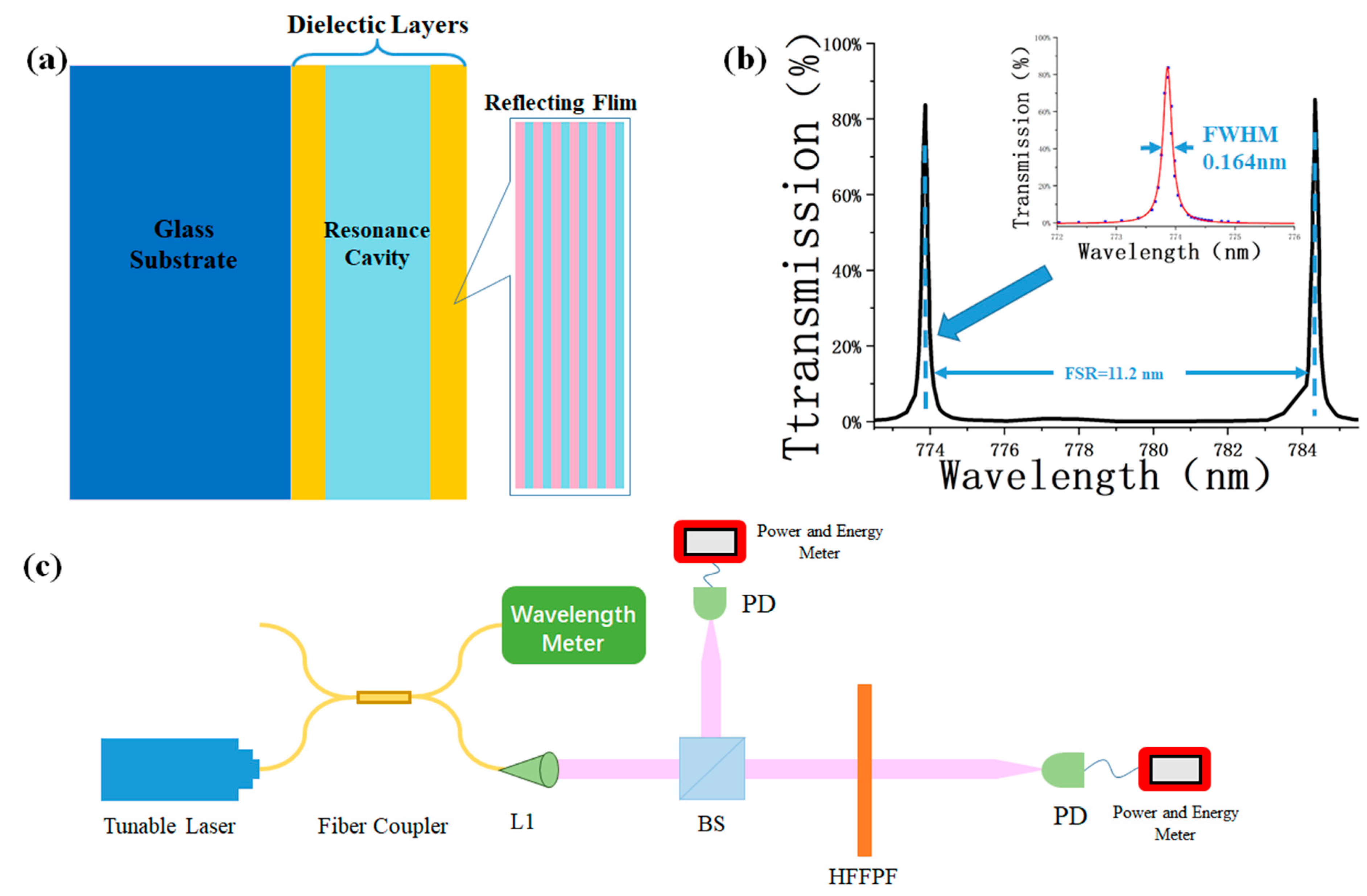
In the experiment, we use the ion-assisted deposition (IAD) [23] method to fabricate the FP cavity, where a thickness accuracy of ~1 nm can be achieved with precise control of the deposition time. As shown in Figure 1a, high-refractive films using eight-layer pairs of Ta2O5 and SiO2 are first deposited on the 8-inch BK7 glass circular substrate, with an effective thickness of 1/4 λ for each layer. Then ~12 μm Ta2O5 is deposited on the refractive film as the resonance cavity layer; hence, the theoretical FSR is ~11.8 nm. Finally, more eight-layer pairs of Ta2O5 and SiO2 with the same reflectivity are deposited on the cavity layer as the second reflective layer. For the 97%-reflectivity layer, the corresponding finesse is ~103.1; hence, the theoretical full-width half-maximum (FWHM) bandwidth is = 0.114 nm. In our fabrication, 10 pieces of 8-inch HFFPF are coated in the same batch, and 3 mm × 3 mm square blocks of HFFPF are sufficient for the self-injection locking experiment. Therefore, ~23,000 narrow-linewidth lasers can be made from a single batch of coating, which is beneficial for mass production (In this estimation, we considered the edge effect for coating and only used the central area with a diameter of 197 mm in each wafer for HFFPF fabrication).
Then, we measure the transmission spectrum of the HFFPF using a tunable external cavity diode laser (DL PRO, TOPTICA Photonics AG, Munich, Germany) with a linewidth of 10 kHz. The measurement setup is shown in Figure 1c, where the fiber-coupled laser beam is directed to a 50:50 fiber coupler for the separation into two output ports. One port is connected to a wavelength meter (WS Ultimate, High Finesse GmbH, Tübingen, Germany) for the precise monitoring of the laser wavelength during the tuning. The laser beam in the other port is used for the HFFPF transmission measurement, which is collimated into free space by an aspherical lens and further split by a 50:50 cubic beam splitter. The transmitting beam is focused onto the HFFPF and then detected by a photodetector (PD). The reflecting beam is detected by another PD for the intensity normalization against the laser power fluctuation during the scanning process, with a wavelength sweeping from 772.5 nm to 785.5 nm. The measured HFFPF transmission is plotted in Figure 1b, and the FSR is measured to be 11.2 nm. There is a small deviation between this value and the theoretical one. It is because to achieve resonance at 785 nm, the actual resonance cavity thickness must be slightly larger than 12 μm. The transmission peak is further zoomed-in in the inset of Figure 1b, where its FWHM bandwidth is fitted to be 0.164 nm. Compared to the theoretical value, the experimental bandwidth is broadened because the actual reflectivity, due to fabrication deviation, is slightly lower than 97%.
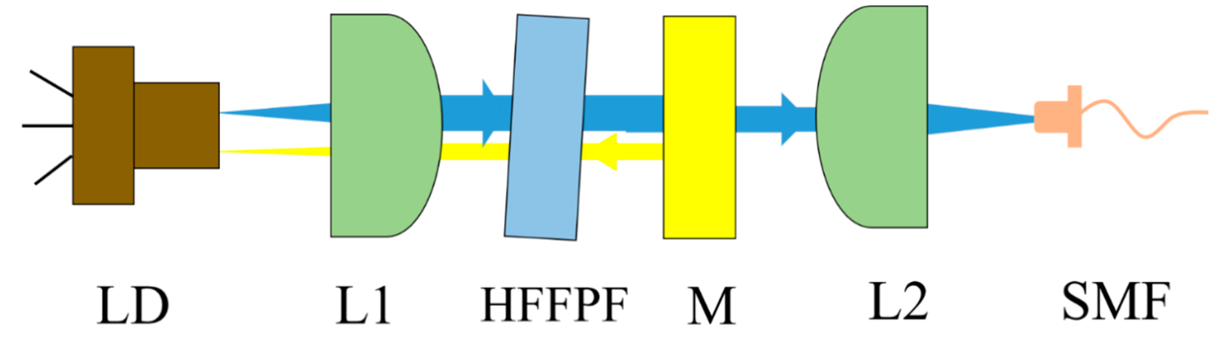
For the laser source in the self-injection, we use a low-cost FP-LD with a TO-can package working at around 785 nm. With a 102.6 mA driven current supplied by a commercial constant-current laser driver module, it has an output power of 49.8 mW. Then we build the self-injection locking setup, as schematically shown in Figure 2. The LD output is first collimated by an aspherical lens, with the beam waist on a 90%-transmissivity partially reflecting mirror, which is used to generate feedback for the self-injection locking. The HFFPF is inset between the aspherical lens and the mirror as a narrowband filter for the laser feedback. It is tilted slightly to optimize the longitudinal mode matching between the HFFPF and the LD cavity and to avoid unwanted feedback from the direct reflection from the HFFPF surface. Another aspherical lens is used to couple laser output into a single-mode fiber. In this laser, the distance between the LD and the partial-reflection mirror is 5 cm; hence, the FSR for this external cavity is ~0.0062 nm. However, due to the low reflectivity, the finesse F’ of the cavity is only ~1.1. So, the HFFPF is necessary for this cavity for frequency filtering to achieve a single-longitude-mode output for the self-injection locking laser.
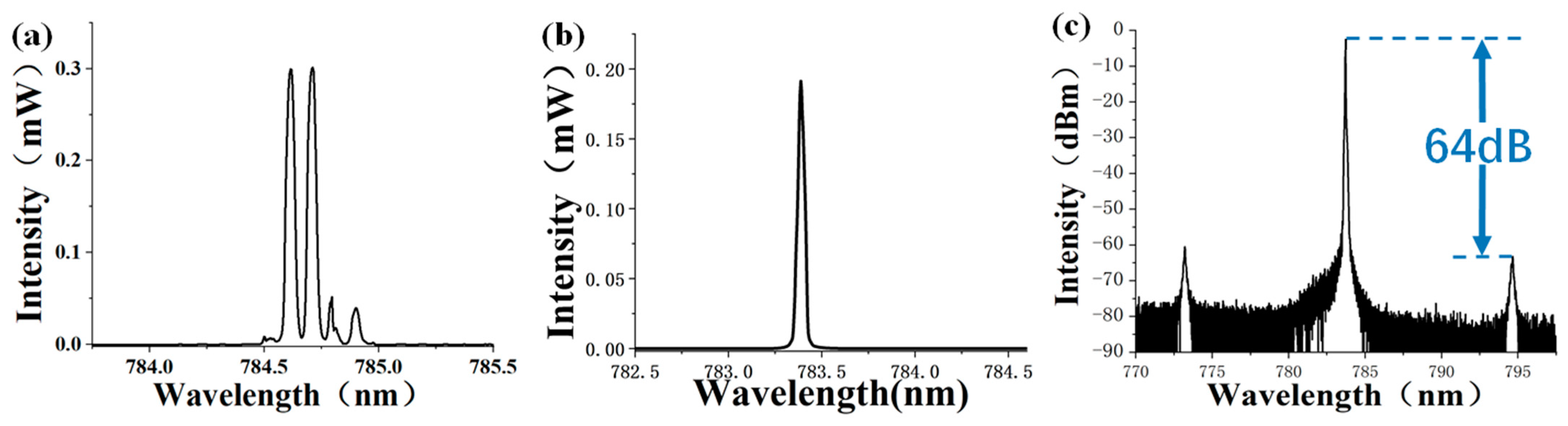
Then we characterize the output spectrum of the self-injection-locked laser. For comparison, we first measure the free-running spectrum of the LD using an optical spectrum analyzer (OSA, AQ6374, YOKOGAWA, Tokyo, Japan), and the result is shown in Figure 3a. The spectrum of the LD before the self-injection locking has several peaks between 784 nm and 786 nm, which shows a multi-longitudinal-mode output. After that, the output spectrum of the self-injection-locked laser is measured. Unlike the multi-longitudinal-mode spectrum in the free-running case, the spectrum presents a clean Lorentz-type single-longitudinal-mode spectrum peaking at 783.4 nm, as shown in Figure 3b. The side modes are compressed well over a large range from 770 nm to 800 nm, with a side-mode suppression ratio of over 60 dB. The wavelength difference between the first side-mode peak and the center one is 11.1 nm, which is consistent with the FSR of the HFFPF. The same spectrum is plotted in logarithmic scale in Figure 3c, and its linewidth is limited by the OSA resolution of about 0.05 nm.
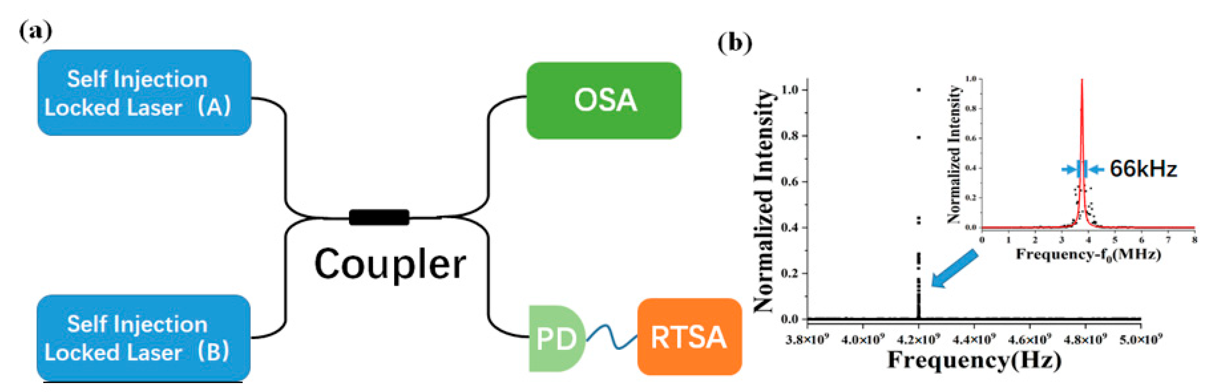
Then, the laser linewidth is measured more accurately using the optical heterodyne measurement [24]. Two self-injection-locked lasers are built for this measurement, with the setup shown in Figure 4a. Two pieces of HFFPF from the same batch are used for these two lasers, and the laser outputs are mixed using a 50:50 fiber coupler for the heterodyne measurement. The OSA is used for a coarse match of the laser frequencies by monitoring the spectrum of one output port. By tuning the LD temperature of one laser, we overlap the spectra of the two laser outputs within the 0.05 nm resolution limit of the OSA. Then we can see the beating signal from the photocurrent of a photodetector linking to the other output port using a real-time spectrum analyzer (RTSA, RSA306B, Tektronix). By setting the beating frequency at around 4.195 GHz, we plot the beating signal in Figure 4b, which shows a sharp RF peak. The inset is a zoom-in of the beating spectrum, and the FWHM bandwidth of the peak is fit to be about 66 kHz. Assuming the two self-injection-locked lasers have the same linewidth, the linewidth of a single laser can be estimated to be 46.7 kHz.
In conclusion, we develop an IAD coating method to demonstrate a high finesse Fabry–Pérot filter with a bandwidth down to 0.16 nm, and a sub-100 kHz narrow-linewidth laser is built using an HFFPF. A high side-mode suppression ratio of 60 dB is measured using only a low-cost FP laser diode. This method greatly simplifies the narrowband filtering in the self-injection-locked laser fabrication and is thus beneficial for mass production. Here, the laser linewidth is limited by the current HFFPF finesse at 70, which may be further increased using reflecting layers with higher reflectivity, where even narrower laser linewidth can be expected. Meanwhile, the current setup size is limited by the TO-can packaged laser diode. By using a non-packaged laser diode chip, the HFFPF can be placed on the chip facet directly without the lenses for beam shaping, and a much more compact setup can be expected for practical applications.
Author Contributions
H.-Y.L. conceived the original idea and designed the experiment, P.F., P.X. and M.S. performed the whole experiment. All the authors helped on the manuscript preparation. H.-Y.L., Z.X. and S.Z. supervised the whole work. All authors have read and agreed to the published version of the manuscript.
Funding
This research was funded by the National Key R&D Program of China (No. 2019YFA0705000), Leading-edge technology Program of Jiangsu Natural Science Foundation (No. BK20192001), National Natural Science Foundation of China (51890861, 11690033), Zhangjiang Laboratory (ZJSP21A001), the Excellent Research Program of Nanjing University (ZYJH002), National Natural Science Foundation of China (62293523), the National Postdoctoral Program for Innovative Talents (BX2021122), China Postdoctoral Science Foundation (No. 2022M711570) and the Fundamental Research Funds for the Central Universities (2022300158).
Institutional Review Board Statement
Not applicable.
Informed Consent Statement
Not applicable.
Data Availability Statement
We have created no new data, or the data is unavailable due to privacy or ethical restrictions
Conflicts of Interest
The authors declare no conflict of interest.
References
- Amann, M.-C.; Bosch, T.M.; Lescure, M.; Myllylae, R.A.; Rioux, M. Laser ranging: A critical review of unusual techniques for distance measurement. Opt. Eng. 2001, 40, 10–19. [Google Scholar]
- Burrows, E.; Liou, K.-Y. High resolution laser LIDAR utilising two-section distributed feedback semiconductor laser as a coherent source. Electron. Lett. 1990, 26, 577–579. [Google Scholar] [CrossRef]
- Al-Taiy, H.; Wenzel, N.; Preußler, S.; Klinger, J.; Schneider, T. Ultra-narrow linewidth, stable and tunable laser source for optical communication systems and spectroscopy. Opt. Lett. 2014, 39, 5826–5829. [Google Scholar] [CrossRef]
- Lu, H.-H.; Li, C.-Y.; Chen, H.-W.; Ho, C.-M.; Cheng, M.-T.; Yang, Z.-Y.; Lu, C.-K. A 56 Gb/s PAM4 VCSEL-based LiFi transmission with two-stage injection-locked technique. IEEE Photonics J. 2016, 9, 1–8. [Google Scholar] [CrossRef]
- Tsai, W.-S.; Lu, H.-H.; Wu, H.-W.; Su, C.-W.; Huang, Y.-C. A 30 Gb/s PAM4 underwater wireless laser transmission system with optical beam reducer/expander. Sci. Rep. 2019, 9, 8605. [Google Scholar] [CrossRef] [PubMed] [Green Version]
- Huang, X.-H.; Li, C.-Y.; Lu, H.-H.; Chou, C.-R.; Hsia, H.-M.; Chen, Y.-H. A bidirectional FSO communication employing phase modulation scheme and remotely injection-locked DFB LD. J. Light. Technol. 2020, 38, 5883–5892. [Google Scholar] [CrossRef]
- Ragheb, A.M.; Tareq, Q.; Esmail, M.A.; Alrabeiah, M.R.; Alshebeili, S.A.; Khan, M.Z. Enabling WiGig Communications Using Quantum-Dash Laser Source Under Smoky Weather Conditions. IEEE Photonics J. 2022, 14, 1–7. [Google Scholar] [CrossRef]
- Grillot, F.; Duan, J.; Dong, B.; Huang, H. Uncovering recent progress in nanostructured light-emitters for information and communication technologies. Light Sci. Appl. 2021, 10, 156. [Google Scholar] [CrossRef]
- Asghar, H.; Sooudi, E.; Baig, M.A.; McInerney, J.G. Recent advances in stabilization of mode-locked quantum dash lasers at 1.55 µm by dual-loop optical feedback. Opt. Laser Technol. 2020, 122, 105884. [Google Scholar] [CrossRef]
- Hens, K.; Sperling, J.; Sherliker, B.; Waasem, N.; Ricks, A.; Lewis, J.; Elgcrona, G. Lasers for holographic applications: Important performance parameters and relevant laser technologies. In Practical Holography XXXIII: Displays, Materials, and Applications; SPIE: Bellingham, WA, USA, 2019; Volume 10944, pp. 29–36. [Google Scholar]
- Wei, X.; Xie, Z.; Zhu, S.-N.J.A.S. Self-injection locking of a distributed feedback laser diode using a high-finesse Fabry-Perot microcavity. Appl. Sci. 2019, 9, 4616. [Google Scholar] [CrossRef] [Green Version]
- Hao, L.; Wang, X.; Guo, D.; Jia, K.; Fan, P.; Guo, J.; Ni, X.; Zhao, G.; Xie, Z.; Zhu, S.-n. Narrow-linewidth self-injection locked diode laser with a high-Q fiber Fabry–Perot resonator. Opt. Lett. 2021, 46, 1397–1400. [Google Scholar] [CrossRef] [PubMed]
- Mukhtar, S.; Ashry, I.; Shen, C.; Ng, T.K.; Ooi, B.S.; Khan, M.Z.M. Blue laser diode system with an enhanced wavelength tuning range. IEEE Photonics J. 2020, 12, 1–10. [Google Scholar] [CrossRef]
- Lin, G.-R.; Wang, H.-L.; Lin, G.-C.; Huang, Y.-H.; Lin, Y.-H.; Cheng, T.-K. Comparison on injection-locked Fabry–Perot laser diode with front-facet reflectivity of 1% and 30% for optical data transmission in WDM-PON system. J. Light. Technol. 2009, 27, 2779–2785. [Google Scholar]
- Lin, G.-R.; Cheng, T.-K.; Lin, Y.-H.; Lin, G.-C.; Wang, H.-L. A weak-resonant-cavity Fabry–Perot laser diode with injection-locking mode number-dependent transmission and noise performances. J. Light. Technol. 2010, 28, 1349–1355. [Google Scholar]
- Chen, M.-H.; Hsiao, S.-C.; Shen, K.-T.; Tsai, C.-C.; Chui, H.-C. Single longitudinal mode external cavity blue InGaN diode laser. Opt. Laser Technol. 2019, 116, 68–71. [Google Scholar] [CrossRef]
- Donvalkar, P.S.; Savchenkov, A.; Matsko, A. Self-injection locked blue laser. J. Opt. 2018, 20, 045801. [Google Scholar] [CrossRef]
- Demir, V.; Akbulut, M.; Nguyen, D.; Kaneda, Y.; Neifeld, M.; Peyghambarian, N. Injection-locked, single frequency, multi-core Yb-doped phosphate fiber laser. Sci. Rep. 2019, 9, 356. [Google Scholar] [CrossRef] [Green Version]
- Spirin, V.V.; Escobedo, J.L.B.; Korobko, D.A.; Mégret, P.; Fotiadi, A.A. Stabilizing DFB laser injection-locked to an external fiber-optic ring resonator. Opt. Express 2020, 28, 478–484. [Google Scholar] [CrossRef]
- Chien, J.-C.; Niknejad, A.M. Oscillator-based reactance sensors with injection locking for high-throughput flow cytometry using microwave dielectric spectroscopy. IEEE J. Solid-State Circuits 2015, 51, 457–472. [Google Scholar] [CrossRef]
- Xi, Y.; Li, X.; Huang, W.-P. Standing-wave model based on modes of cold cavity for simulation of laser diodes. In Integrated Photonics and Nanophotonics Research and Applications; Optica Publishing Group: Washington, DC, USA, 2007; p. ITuF3. [Google Scholar]
- Guo, J.; Jia, K.; Wang, X.; Huang, S.-W.; Zhao, G.; Xie, Z.; Zhu, S.-N. Single-frequency Brillouin lasing based on a birefringent fiber Fabry–Pérot cavity. Appl. Phys. Lett. 2022, 120, 091102. [Google Scholar] [CrossRef]
- McNeil, J.R.; Barron, A.C.; Wilson, S.; Herrmann, W.C. Ion-assisted deposition of optical thin films: Low energy vs high energy bombardment. Appl. Opt. 1984, 23, 552–559. [Google Scholar] [CrossRef] [PubMed]
- Fee, M.S.; Danzmann, K.; Chu, S. Optical heterodyne measurement of pulsed lasers: Toward high-precision pulsed spectroscopy. Phys. Rev. A 1992, 45, 4911. [Google Scholar] [CrossRef] [PubMed] [Green Version]
Figure 1.
(a) Structure of the HFFPF. The dark blue layer is the glass substrate, and the two yellow layers are high-reflection films, while the blue layer is the resonance cavity formed by 12-μm Ta2O5. The inset shows the structure of the high-reflection film, which is formed with eight-layer pairs of Ta2O5 and SiO2, with a designed reflectivity of 97%. The Ta2O5 and the SiO2 layers are marked in blue and pink, respectively. (b) The measured transmission spectrum of HFFPF. (c) The setup diagram for the transmission spectrum measurement. L: aspherical lens; BS: beam splitter; PD: photodetector.

Figure 2.
Setup of the self-injection-locked laser using the HFFPF. LD: laser diode; L: aspherical lens; HFFPF: High finesses Fabry–Pérot filter; M: 90 %-transmissivity partial-reflection mirror; SMF: single mode fiber.
Figure 2.
Setup of the self-injection-locked laser using the HFFPF. LD: laser diode; L: aspherical lens; HFFPF: High finesses Fabry–Pérot filter; M: 90 %-transmissivity partial-reflection mirror; SMF: single mode fiber.

Figure 3.
(a) The free-running spectrum of the laser diode. (b) The spectrum of the self-injection-locked laser diode. (c) The spectrum in the logarithmic scale.
Figure 3.
(a) The free-running spectrum of the laser diode. (b) The spectrum of the self-injection-locked laser diode. (c) The spectrum in the logarithmic scale.

Figure 4.
(a) Setup for the heterodyne measurement. OSA: optical spectrum analyzer; PD: photodetector; RTSA: real-time spectrum analyzer. (b) Beating signal measured in optical heterodyne measurement. The black dots are measured data, and the red curve is its Lorentz fitting. In the zoom-in figure, f0 = 4.197 GHz.

Disclaimer/Publisher’s Note: The statements, opinions and data contained in all publications are solely those of the individual author(s) and contributor(s) and not of MDPI and/or the editor(s). MDPI and/or the editor(s) disclaim responsibility for any injury to people or property resulting from any ideas, methods, instructions or products referred to in the content. |
© 2023 by the authors. Licensee MDPI, Basel, Switzerland. This article is an open access article distributed under the terms and conditions of the Creative Commons Attribution (CC BY) license (https://creativecommons.org/licenses/by/4.0/).
Share and Cite
MDPI and ACS Style
Fan, P.; Xu, P.; Liu, H.-Y.; Shang, M.; Xie, Z.; Zhu, S. A Compact Self-Injection-Locked Narrow-Linewidth Diode Laser with Narrowband Dielectric Filter. Appl. Sci. 2023, 13, 4765. https://0-doi-org.brum.beds.ac.uk/10.3390/app13084765
AMA Style
Fan P, Xu P, Liu H-Y, Shang M, Xie Z, Zhu S. A Compact Self-Injection-Locked Narrow-Linewidth Diode Laser with Narrowband Dielectric Filter. Applied Sciences. 2023; 13(8):4765. https://0-doi-org.brum.beds.ac.uk/10.3390/app13084765
Chicago/Turabian StyleFan, Pengfei, Peng Xu, Hua-Ying Liu, Minghao Shang, Zhenda Xie, and Shining Zhu. 2023. "A Compact Self-Injection-Locked Narrow-Linewidth Diode Laser with Narrowband Dielectric Filter" Applied Sciences 13, no. 8: 4765. https://0-doi-org.brum.beds.ac.uk/10.3390/app13084765
Note that from the first issue of 2016, this journal uses article numbers instead of page numbers. See further details here.