Article

Directional-Sensitive X-ray/Gamma-ray Imager on Board the VZLUSAT-2 CubeSat for Wide Field-of-View Observation of GRBs in Low Earth Orbit

1
Advacam, U Pergamenky 1145/12, 170 00 Prague, Czech Republic
2
Faculty of Electrical Engineering, Czech Technical University in Prague, Technicka 1902/2, 166 27 Prague, Czech Republic
3
Engelhardt Observatory, Kazan Federal University, Kremlyovskaya St., 18, 420008 Kazan, Russia
4
Rigaku Innovative Technologies Europe, Novodvorska 994/138, 142 00 Prague, Czech Republic
5
Faculty of Nuclear Science, Czech Technical University in Prague, Brehova 7, 115 19 Prague, Czech Republic
6
Czech Aerospace Research Centre, Beranovych 130, 199 00 Prague, Czech Republic
7
Institute of Physics, Academy of Sciences of the Czech Republic, Na Slovance 1999/2, 182 21 Prague, Czech Republic
*
Author to whom correspondence should be addressed.
Submission received: 28 February 2022 / Revised: 4 April 2022 / Accepted: 6 April 2022 / Published: 13 April 2022

Abstract

:
We present a miniaturized and wide field-of-view X-ray and Gamma-ray imager consisting of a segmented 2D optics-collimator coupled to the high-sensitivity semiconductor pixel detector Timepix equipped with a high-Z sensor (CdTe 2000 μ m thick). The compact payload has been deployed in low-Earth orbit (LEO) onboard the 3U Cubesat VZLUSAT-2 which was launched on 13 January 2022. The instrument is designed to verify small spacecraft borne observation in open space of hard X-ray and Gamma-ray sources both of celestial and atmospheric origin. High-resolution spectral-sensitive X-ray and Gamma-ray images are provided with enhanced event discrimination and wide field-of-view up to 60 ° . Description of the instrument together with response evaluation and tests in ground with well-defined sources are presented. The intended observational plan for in-orbit measurements is outlined along with astrophysical goals and issues.

1. Space-Borne X-ray and Gamma-ray Observational Research

The recent progress in CubeseSats [1,2] technologies allows for novel scientific payloads and fast-track scientific missions to be considered and developed. Progress includes small spacecraft steering capabilities and attitude control which bring additional possibilities for CubeSat missions such as tandem flights or CubeSat constellation fleets [3,4]. The tandem flight arrangement can, for example, allow for the deployment of payloads with focal lengths exceeding the typical dimensions of nanosatellites.
In this direction there is a recent effort to develop innovative high-sensitivity but miniature instruments to exploit these new possibilities. The payloads should ideally be of small size with highly integrated electronics and low power consumption [5,6].
The X-ray and Gamma-ray sky is rich in many types of variable, transient, and flaring stellar sources. In addition to the space sources, there are also high-energy triggers in and above Earth’s atmosphere such as terrestrial Gamma-ray flashes (TGF) and auroral emissions [7]. For purposes of imaging of such sources on space-borne deployments, the focusing of hard X-rays above 100 keV as well as of gamma rays is particularly challenging. Most space imaging experiments in hard X-rays and soft Gamma-rays in the past make use of coded masks which are heavy and ineffective.

1.1. Previous Space-Borne Developments, Other Technologies

In the field of X-ray and Gamma-ray astronomy and space-borne astrophysics several types of miniature scientific payloads have been developed in the past [8]. A first-generation highly miniaturized X-ray focusing telescope [9,10] is deployed since 2017 in LEO onboard the Czech VZLUSAT-1 2U satellite [11,12]. This first generation device consists of a one dimensional (1D) Lobster eye X-ray optics system and the photon-counting semiconductor pixel detector Timepix [13] equipped with a low-Z semiconductor sensor (silicon 300 μ m thick)) as focal-plane X-ray imager. Several other promising payloads are based on various types of detectors and X-ray optics [14,15]. Additional CubeSat based experiments are either in preparation or under study [4,6,16,17,18,19,20,21].
The capability of solid-state detectors equipped with high-Z materials such as CdTe/CdZnTe sensors in high-energy astronomy was demonstrated by the European astronomical satellite, INTEGRAL (INTErnational Gamma-Ray Astrophysics Laboratory [22]) and also by the BAT instrument on board the satellite SWIFT [23]. INTEGRAL is a space mission dedicated to study the Gamma-ray sky. It was launched on 17 October 2002 by a Russian PROTON rocket into an elongated elliptical orbit with a revolution period of three sideral days. Such an orbit significantly decreases the background level caused by Van Allen belt particles and provides long periods of uninterrupted measurements. INTEGRAL is still in use. The imager IBIS (Imager on Board the INTEGRAL Satellite) provides imaging and measurement of celestial Gamma-ray sources. The imager is based on a large array of pixels, all physically distinct. The IBIS detector has two parallel planes of pixels, one on top of the other. Such an approach allows measurement of both low and high energy photons. The upper layer has 16,384 CdTe (Cadmium-Telluride) pixels and the lower layer has 4096 CsI (Cesium-Iode) pixels. IBIS imager provides an angular resolution of 12 arcmin in the energy range 15 keV–10 MeV [22].

1.2. 3U Cubesat VZLUSAT-2

VZLUSAT-2 is a 3U Cubesat from Czech Republic launched as technology demonstrator mission on 13 January 2022 [24]. Deployed into LEO (sun synchronous, 500 km) the telemetry and communication with the satellite are performed via ground station of the Faculty of Electrical Engineering, University of West Bohemia [25]. The mission of VZLUSAT-2 is to verify technologies at the platform and payload levels for future missions of a Czech-based satellite constellation.
The nanosatellite is equipped with an experimental camera and a system for precise attitude control and carries payloads for Earth observation and space radiation monitoring. For X-ray and Gamma-ray astronomy it carries a dedicated payload onboard (see below) which consists of an X-ray and Gamma-ray optics and collimator system coupled to the high-sensitivity semiconductor pixel detector Timepix. Part of the VZLUSAT-2 mission is to verify the new concept of this payload.

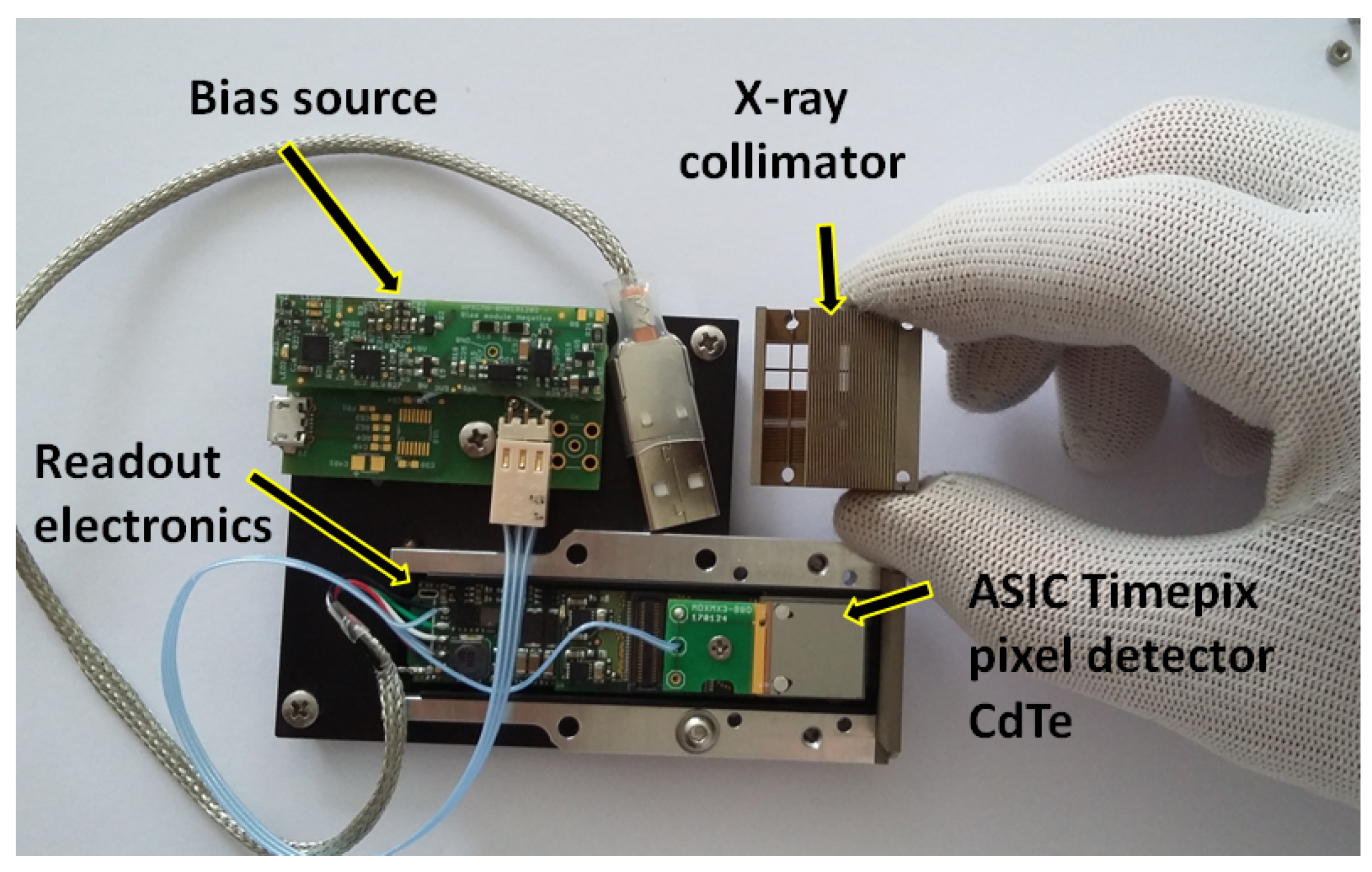
2. Miniaturized X-ray/Gamma-ray Imaging Payload

The instrument is deployed in LEO as technology demonstrator payload (shown in Figure 1) onboard VZLUSAT-2 and is designed for the observation and high-resolution imaging of the hard X-ray and Gamma-ray component (5.0 keV–500 keV) in the cosmic ray field in open space.
The device consists of two components: the integrated optical collimator in the form of a wide-angle metal element and the focal-plane X-ray imager provided by the high-resolution semiconductor pixel detector Timepix. The assembled instrument has an overall size below 9 cm, power consumption 2 W, and mass below 100 g, including casing and holders (see Figure 1). The payload was designed and built by the Czech company Rigaku Innovative Technologies Europe s.r.o. (RITE) including the optical-collimating wide-angle metal unit. The pixel detector in the customized configuration was manufactured and provided by Advacam, Prague, including its equalization and per-pixel energy calibration. The novel architecture of the developed device is given by the unique design of the segmented array of optical-collimators and wide-angle metal element (RITE) and the high-sensitivity and spectral imaging response of the customized high-Z sensor MiniPIX-TPX detector (Advacam).

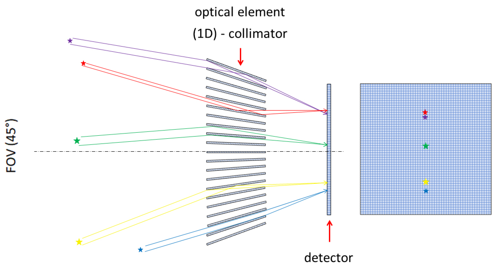
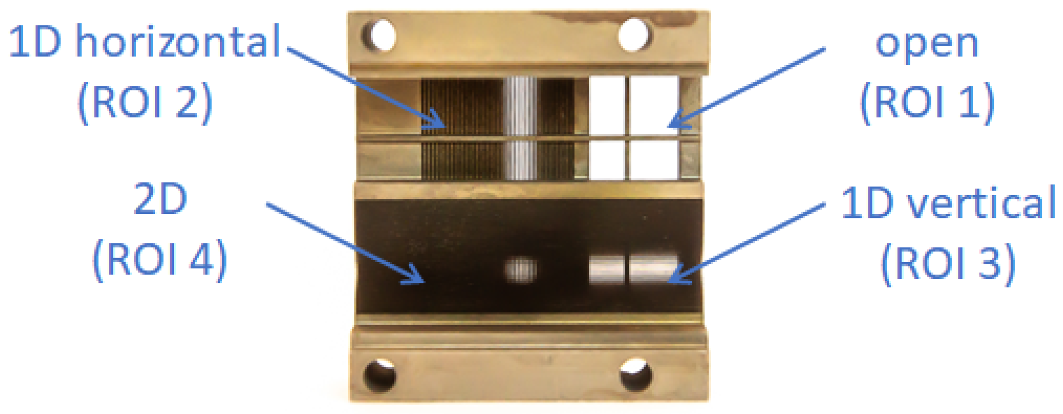
2.1. X-ray Optics Collimator

Observing hard X-ray and cosmic gamma rays is a challenging task. High-energy photons penetrate many materials relatively easily and therefore cannot be focused in the focal plane of the device using conventional optical mirrors or lenses. Customized optical elements and relatively complex mathematical image deconvolution procedures are used to determine them.
The selected approach consists of an array of collimators manufactured from high-Z material (tungsten) closely coupled to the imaging detector. The purpose is to perform as a highly integrated X-ray/Gamma-ray optical element-collimator for both hard X rays above few keV and gamma rays below 500 keV. The principle of operation is illustrated in Figure 2. The task of the wide-angle metal element is to track the Sun, as well as potential bright triggers (both of space and of Earth origin) in hard X-rays and serve as a directional screen.
The X-ray/Gamma-ray optical element-collimator, shown in Figure 3, is divided into 4 segments or quadrants (each 7 mm × 7 mm) of distinct response:
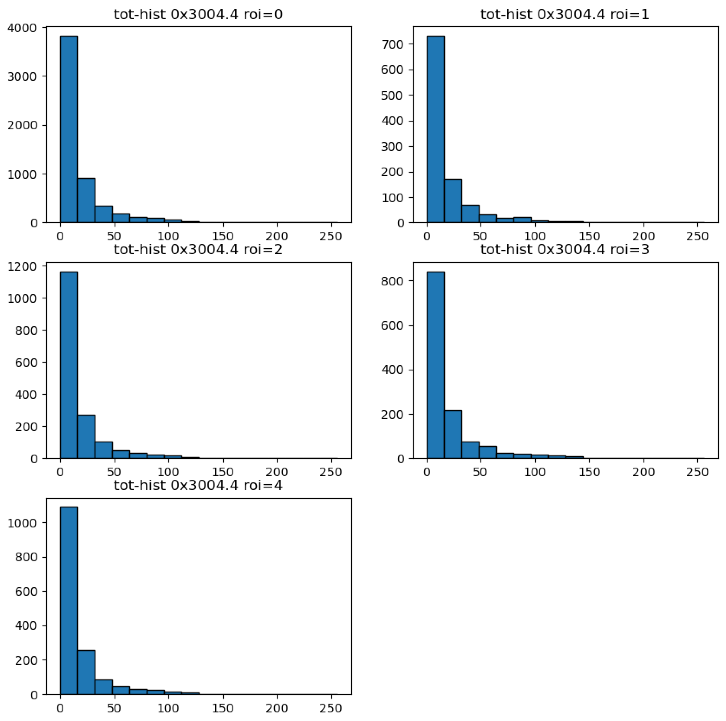
  • ROI = 1: open quadrant with wolfram cross frame
  • ROI = 2: horizontal 1D segment
  • ROI = 3: vertical 1D segment
  • ROI = 4: combined 2D segment.
The segmented arrangement represents an integrated and combined concept which makes use of the detector high granularity and size (active sensor area 14 mm × 14 mm = 2 cm 2 ) together with the highly-sensitive detection of quantum-imaging response (described below).

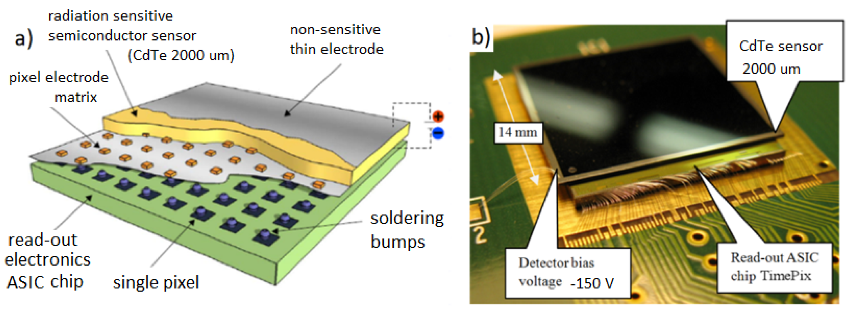
2.2. Focal Plane X-ray/Gamma-ray Imaging Detector

The focal plane X-ray and Gamma-ray imager is provided by the semiconductor pixel detector Timepix [13]. Timepix operates in room temperature and in vacuum and provides photon-counting sensitivity which is valuable for long exposures of weak intensity objects such as stellar X-ray sources in space. The pixel detector consists of the state-of-the-art Timepix ASIC chip which is bump-bonded to a 2 mm thick CdTe sensor (Figure 4). The high-Z material for the sensor and thickness provide enhanced detection of hard X rays and gamma rays up to 500 keV. The detector provides a high-granularity matrix of 256 × 256 = 65 k pixels of size 55 μm and independent per-pixel signal electronics.
The detector is implemented in the miniaturized MiniPix-TPX architecture [26] which consists of highly integrated readout electronics. The connector interface for the detector is USB 2.0 for integrated control, power, and readout of the pixel detector. In this implementation architecture Timepix can be readout a with data rate of up to 45 frames per second (fps). The semiconductor sensor receives bias voltage (−150 V) by separate voltage source (Figure 4). Overall power consumption is below 2 W. About two thirds of this ends up in the form of heat by the detector ASIC chip which is necessary to cool by passive (thermal contact) cooling coupling to the payload casing enclosure.

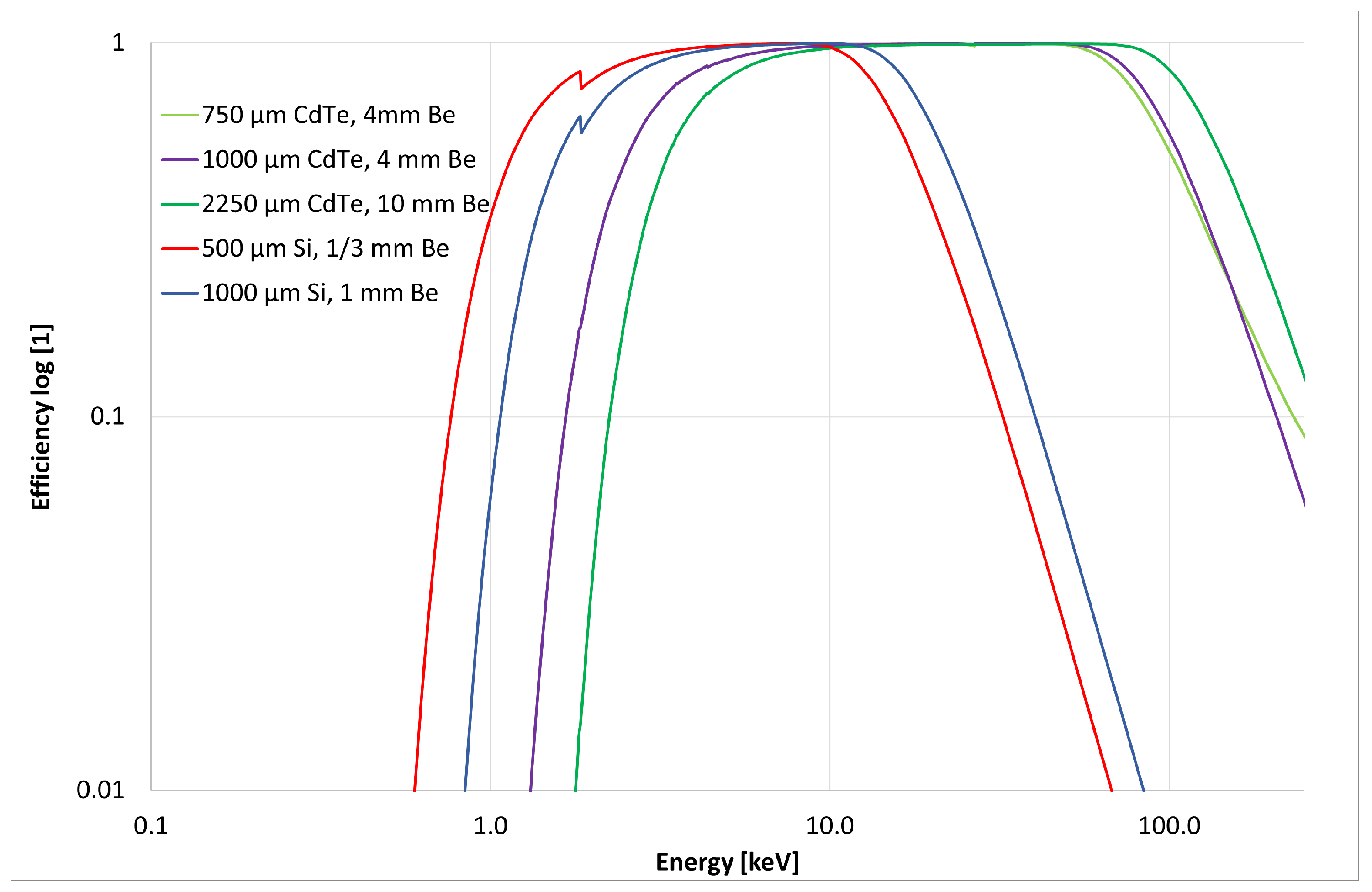
2.3. CdTe Sensor for Enhanced Efficiency of Photon Detection

The pixel detector is equipped with a radiation-sensitive semiconductor sensor of a high-Z material (CdTe) and increased thickness (2000 μ m thick). This detector-sensor configuration is customized for enhanced detection of high energy X rays and gamma rays. The detection efficiency of the photon component depends on the sensor material and thickness as shown in Figure 5. For the sensor configuration used, the detection efficiency for 500 keV gamma rays is at the level of 2 % .

2.4. Payload Operation, Data Handling and Storage

The payload imaging detector (see Section 2.2) is controlled and readout via USB interface. Data handling and storage are done by payload computer or the spacecraft OBC which can be implemented in the form of a high-level computer running in standard operating system (MS Windows, Linux, Mac OS) or low-level CPU e.g., ARM or Raspberry platform. The necessary software (SW) for control and readout of the pixel detector, provided also by Advacam, have been implemented accordingly for high-level or low-level space deployment platforms. Additional functionality implemented include autonomous adjustment of frame acquisition of the pixel detector based on modeled orbit and satellite path. This function allows to optimize and maximize the data rate, payload operation uptime and radiation measurement duty cycle. Radiation data is acquired by the pixel detector readout by the satellite computer where they are also navigation stamped (position, altitude, attitude, time). The payload has been developed also with limited data processing capability on board the Cubesat platform. This option enables specific functions such as basic event filtering (see Section 3.1) and radiation storm alarm output.

2.5. Radiation Imaging, Detector Operation Modes

Radiation imaging data are acquired by the pixel detector (see Section 2.2) in two modes: energy mode and imaging mode (see Section 3.1). The detector data stored include information on the number of single pixels hit by radiation or also in the form of an energy histogram (deposited energy spectra). Additionally developed SW onboard enables partial processing of the measured data in orbit (single-photon filtering, image projection profiles or image reduction to lower resolution).
The entire radiation field is measured during the detector operation exposure time which is suitably set typically in the range from ms up to seconds and longer. During this period a detector frame is registered and subsequently readout with a dead time which is overall at the level of few tens of ms during which no further radiation is registered.

2.6. Deployment as Space Radiation Monitor

Besides the primary function of the payload as focal-plane X-ray imager, the device can operate also as a high-resolution space radiation monitor [28]. The embedded Timepix detector enables to characterize the mixed-radiation field environment in wide-range along the spacecraft orbit. The composition and spectral characterization of the charged particle field of both light and heavy charged particles can be provided in wide range in terms of particle-event types, energy loss and direction [29,30]. This secondary function is used in the Timepix X-ray telescope payload [9] onboard the VZLUSAT-1 CubeSat, launched in 2017 and operating in LEO, now entering its 5th year of operation in open space. Together with navigation data, the Timepix detector provides detailed space radiation maps which serve to determine the background and unwanted event component in the X-ray imaging data of the VZLUSAT-1 Timepix X-ray telescope.

2.7. Astrophysics Observational Applications

The intended application areas of the instrument are as follows: (i) Sun sensor/tracker, (ii) capturing bright triggers (both of space as well as of Earth origin) in hard X-rays, (iii) directional screen and verification of the radiation shielding of the detector, (iv) X-ray high resolution sky mapping, and (v) high-resolution space radiation monitor with enhanced X-ray and Gamma-ray sensitivity.
Deployment in space for astrophysics applications requires stable and accurate location and orientation control of the spacecraft platform. Attitude control accuracy is required at the sub-degree level with stability in the range of tens of minutes for necessary long exposure of stellar X-ray and Gamma-ray objects.

3. Energy-Sensitive X-ray and Gamma-ray Imaging in Wide FoV

The instrument is designed to provide high-resolution images of X-ray and Gamma-ray fields in wide field-of-view. This capability is possible by the combined operation of the high-sensitivity imaging detector Timepix equipped with high-Z sensor together with the developed optical-collimator element. The response and properties of the key components are described and evaluated as follows.

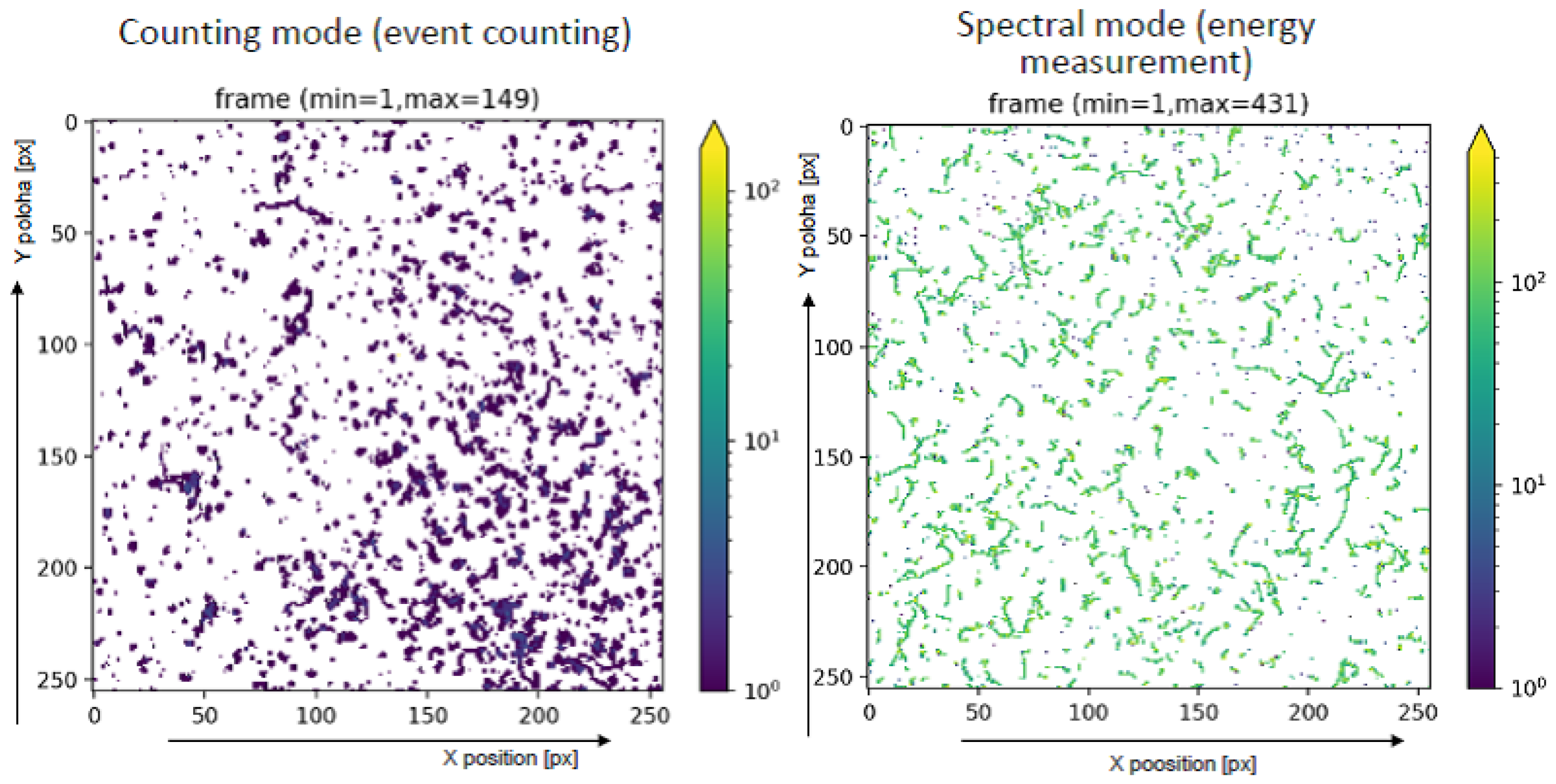
3.1. Photon-Counting Sensitivity, Quantum-Imaging Detection

The hybrid architecture of Timepix, the high granularity and the integrated per-pixel signal electronics enable to operate the detector at room temperature while effectively suppressing noise to provide dark-current free operation and quantum-counting sensitivity of single particles [29]. Timepix operates as a radiation camera [26] registering single particles and visualizing individual pixelated tracks (called c l u s t e r s ) produced in the detector sensor. Such clusters exhibit a wide range of variability in terms of cluster size (number of pixels), morphology (shape contour) and deposited energy which are to a large extent determined by the particle type, deposited energy and direction [29]. Tracks produced by X-rays appear as small, i.e., a few pixel clusters. Tracks produced by gamma rays are registered as larger curly narrow clusters. Charged particles produce a wide morphology of clusters [29]. Analysis of this spectral-tracking response of the pixel detector enables the resolution of the registered particles into various broad-classes of particle-type events [29].
The position of interaction, deposited energy or time of interaction of single particles are individually registered in high-spatial resolution and in wide range in terms of radiation fluxes, energy and direction with particle-type resolving power [29]. Combined with the registration and visualization of single particle tracks in the semiconductor sensor matrix, the Timepix detector provides highly sensitive q u a n t u m - i m a g i n g detection to individual particles in a mixed-radiation field [30]. Together with enhanced radiation shielding of the spacecraft payload, use of the Timepix detector enables discrimination of background and unwanted events. The per-pixel spectral response of Timepix enables to provide energy-sensitive imaging of the detected X rays and gamma rays. Registered particles can be thus spectrally characterized, filtered, and further processed to produced selective energy-binned images as well as deposited energy spectra, particle fluxes, dose rates and LET spectra with particle-type resolving power [29].

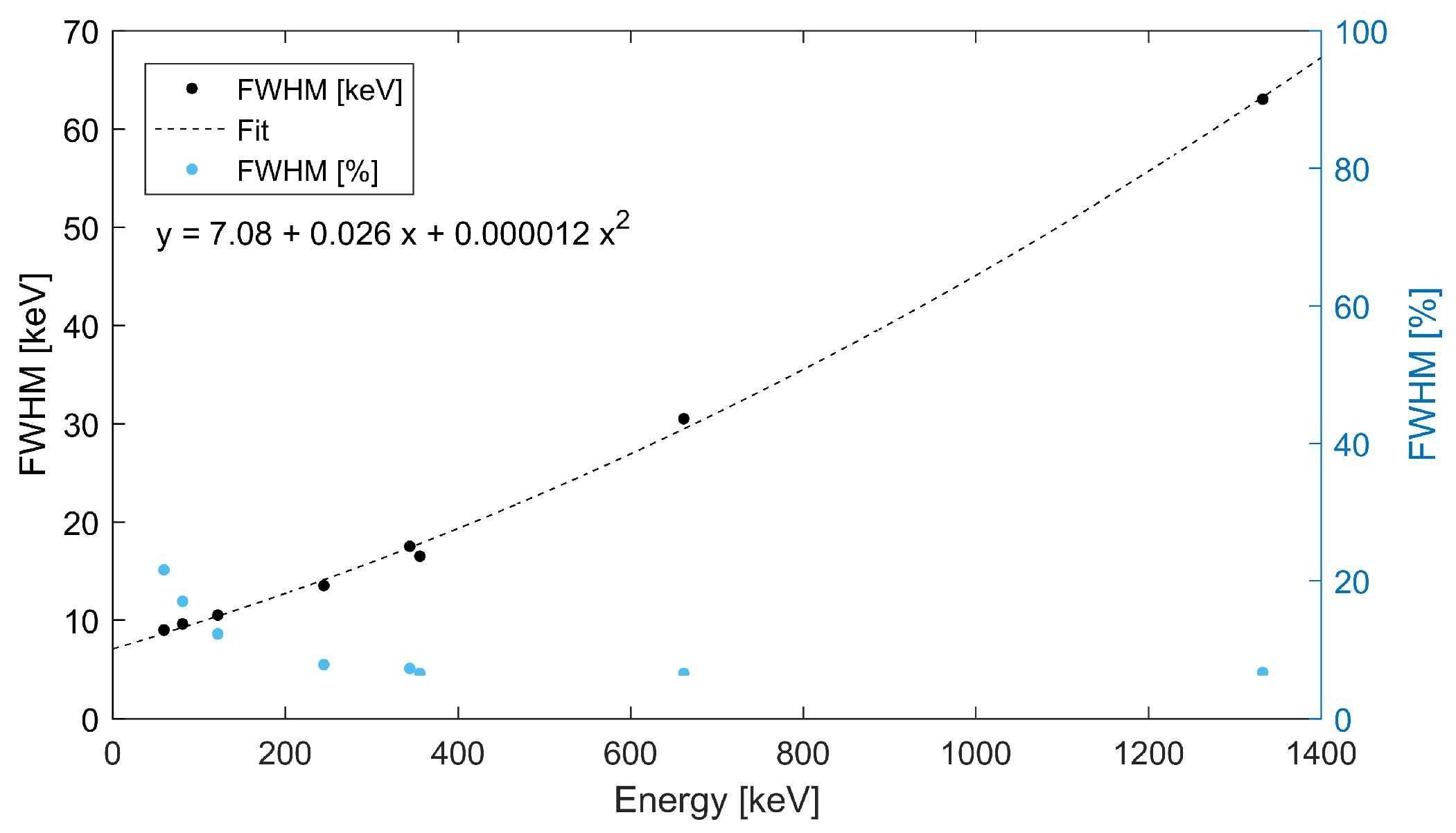
3.2. Spectral-Sensitive Imaging, Energy Resolution

The energy-sensitive imaging response was tested in terms of energy range and collimator transmission efficiency. Tests were performed with laboratory X-ray RTG units including measurements in vacuum chambers. The experimental set-up in the air for detection and imaging of collimated X-ray and field-of-view (FoV) measurement is show in Figure 6. A micro-focus X-ray tube with wolfram anode was used as the X-ray source, which provides a broad spectra of tunable ranges (set by the X-ray unit voltage).
Prior to operation and radiation imaging tests, the pixel detector was equalized including per-pixel response threshold and energy calibration. Timepix is energy calibrated at the per-pixel level with the use of discrete-energy X rays and low-energy gamma rays [31]. We investigated the dependence on voltage of the Wolfram X-ray source on the images produced by the detector coupled to the optical collimator in front. Results for the examined range from 20 kV to 120 kV are given in Figure 7. The specific collimator segments described above are resolved and were characterized. Moreover, the influence of radiation energy change was tested. Verification of transmission suppression of selected metal optical element, of customized design, was also performed for the X-ray source of high voltage (120 kV).
The energy of the X rays and gamma rays detected is measured by the spectral response of the Timepix detector. Energy spectra can be produced for the entire detector region and for the separate collimator/optics regions. The spectral sensitivity and energy resolution of the device are given by the spectral response of the pixel detector. For X rays and gamma rays the resolution for the Timepix detector with a CdTe sensor is at the level between 4% and 15% for the high (>300 keV) and low (<100 keV) energy range, respectively. The energy resolution depends on the energy as shown in Figure 8. Experimental values of the full width at half maximum were measured for selected gamma rays of discrete energy from calibrating sources ( 241 A m , 152 E u , 133 B a , 137 C s , 60 C o ).

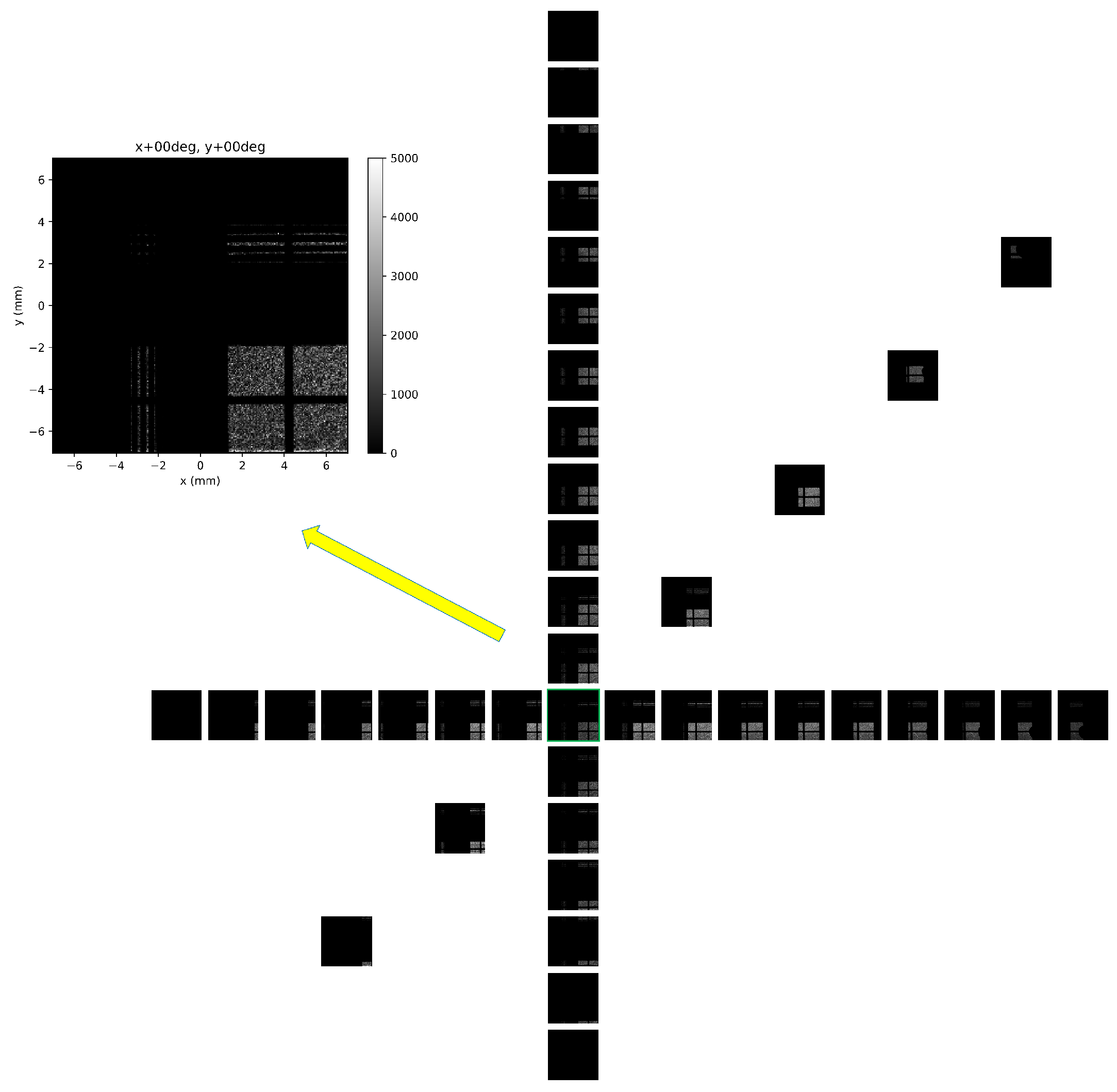
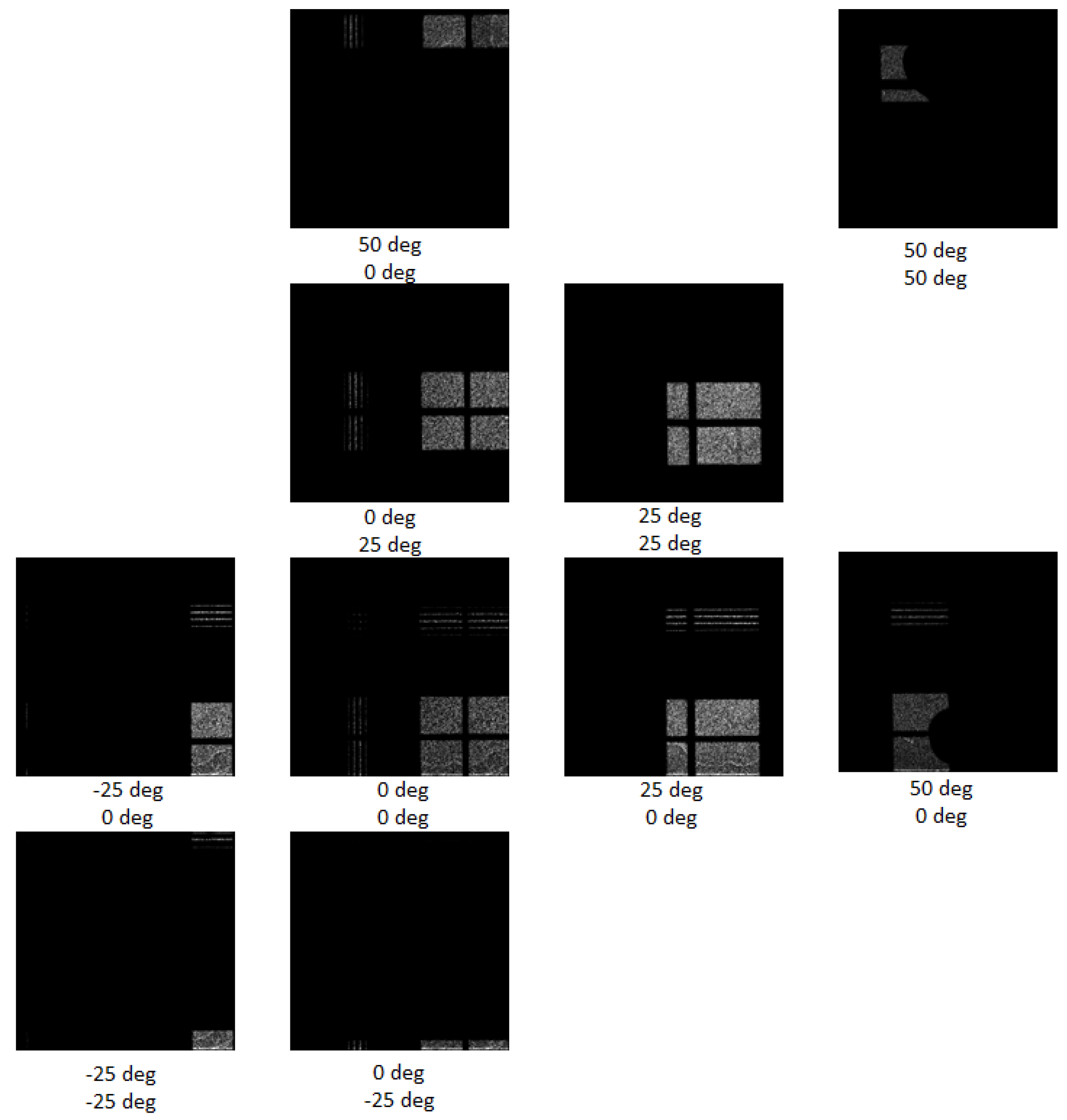
3.3. Directional Response, Field-of-View

The directional response of the instrument was evaluated in frame of the ground-based tests prior to integration for the CubeSat VZLUSAT-2 launch. The angular acceptance and directional response expressed in terms of the Field-of-View (FoV) was tested by scanning between −35 to +60 degrees in both directions (vertical, horizontal and diagonal scan). Measurements were performed with a laboratory X-ray RTG unit. The directional response in wide FoV range is shown in Figure 9. The optical-collimator pattern registered by the pixel detector gradually shifts along the indicated directions. This effect can be more clearly seen in the expanded detector images at selected directional positions shown in Figure 10. The FoV of the imager, given by the optics/collimator acceptance, is 35 × 35 deg.

3.4. Effective Area, Geometric Factor

The effective area of the device as X-ray and Gamma-ray imager is given by the area of the radiation sensitive sensor of the pixel detector coupled to the effective area of the optics collimator. The Timepix detector provides a sensitive matrix of 256 × 256 pixels for a total area of 14.08 mm × 14.08 mm = 1.98 cm 2 . The effective area of the collimator/optics element consists of four quadrant regions, each of 7 mm × 7 mm, for total effective area 14 cm × 14 cm = 4 cm 2 . The resulting geometric area for the assembled imager is thus the same as the effective area of the detector (1.98 cm 2 ).

3.5. Spatial and Angular Resolution

The developed device is configured for X-ray/Gamma-ray imaging. The spatial and angular resolution for detection and directional imaging of X-rays and Gamma-rays is given by the angular acceptance and resolution of the collimator/optics architecture coupled to the detector spatial resolution. At the detector level, single photons are detected with spatial resolution at the pixel pitch size (55 μ m) with no directional response. The directional sensitivity of the Timepix detector itself is applicable to energetic charged particles to which spectral-tracking analysis is implemented [26]. For X-ray and Gamma-ray photons the collimator/optics element is used to provide directional sensitivity. The angular resolution for the 2D and 1D quadrant elements is 0.5 deg (ROI 1, 3, and 4) and for the open quadrant element is 3 deg (ROI 2) (Section 2.1). The angular resolution essentially does not vary in the given acceptance range.
The resulting sensitivity of the assembled device, in the examined region (below few hundred keV), has only small variability on the photon energy. This is due to the partial decrease in the detection efficiency of the pixel detector to high-energy photons. The angular response, given namely by the optical/collimator element, has essentially no variability on the photon energy.

3.6. Radiation Field Component Discrimination, Segmented Region Response

The detection response and resolving power of radiation field composition was investigated. Tests were performed with a mixed field of X ray, gamma ray and alpha particle components from a laboratory radionuclide 241-Am source. The integrated detection (i.e., over many individual Timepix frames) and track visualization of the irradiated field by the instrument are presented in Figure 11.
The results shown correspond to two measuring modes of the Timepix detector which are suitable for performance testing purposes of the developed instrument. The c o u n t i n g m o d e allows for detailed event counting at the pixel level and serves for determination of the position of the X-ray source. The s p e c t r a l m o d e allows for energy measurement also at the pixel level and is suitable for the production of deposited energy spectra of registered particles. Figure 12 shows 5 histograms corresponding to the whole detector (ROI = 0) and the 4 segmented quadrants of the segmented optics-collimator (ROI = 1: 1D horizontal, ROI = 2: open window with cross frame, ROI = 3: 2D, ROI = 4: 1D vertical quadrant) - see description list in Section 2.1. A broad binning was chosen given the spectral resolution and resolving power of the pixel detector [29]. The ratios and derived pattern distributions serve to characterize the response and operational range between the segment regions.

4. Observational Plan and Intended Measurements in Orbit

4.1. Observational Strategy and Operation in Orbit

Following the commissioning phase, the proposed observation plan in orbit with the developed payload includes the following steps:
  • payload tests, instrumentation performance in the orbit and space environment conditions
  • verifying the use of the planner and testing cyclic commands such as slides
  • exposure prediction depending on the flight over a specific area from 10 ms to 20 s (for 2-day data collection)
  • measurement of the earth’s radiation map (two days—one map)
  • long-term monitoring of the solar spectrum with the need for single-photon data filtering
  • In the case of the function of orientation and stabilization, the search for bright triggers—including the long-term monitoring of the sky in Gamma-rays. In connection with the VIS camera—star-tracker—position determination of the source could be feasible.

4.2. Astrophysical Goals and Issues

Detecting and observing celestial targets in space in the spectral region of hard X-rays and low-energy gamma rays remains a challenging task especially with small instrumentation suitable for nanosatellite deployment. There is a need for novel ideas regarding how to further miniaturize astrophysical payloads to fit the limited volumes and mass limits of CubeSats [8,15].
However, there are also expectations for additional application areas such as detection and analyses of high-energy events in the Earth atmosphere such as terrestrial gamma ray flashes (TGF) and auroral X-ray emissions. Having a CubeSat on very low orbit, even miniature instrumentation can provide valuable scientific data due to high fluency of radiaton from these phenomena. This orbit type, including necessary drives, is recently under study at the Czech Technical University in Prague, Faculty of Electrical Engineering, in collaboration with external partners.
The X-ray and Gamma-ray sky in the energy range covered by the experiment described is rich in violent and variable sources such as high mass X-ray binaries (HMXB), low mass X-ray binaries (LMXB), cataclysmic variables (CV), active galactic nuclei (AGNs), and Gamma-ray bursts (GRBs) [32,33]. The spectral energy distribution of samples of GRBs is well consistent with the energy range 5 keV - 0.5 MeV of the payload described in this paper [34].
Approximately 50% of all GRBs observed by BATSE within the 1 MeV energy range have a peak energy between 70 and 500 keV. However, the cutoff power-law model (CPL) [35] suggests that most arriving photons are of lower energy than the reported energy. Furthermore, long GRBs and afterglows are also predominantly located within the lower energy range. Thus, the effective observation of GRB favors s detector energy range from 10’s keV to no less than 500 keV. The region above 700 keV is expected to provide limited impact.
In the sample of more than 300 GRB detected by Suzaku wide-band all-sky monitor covering the energy range 100–10,000 keV [36], the energy fluence ranged from 2.87 × 10 7 to 3.15 × 10 4 erg cm 2 for long bursts and 4.39 × 10 7 to 9.57 × 10 6 erg cm 2 for short bursts. This is equal to from 1.16 to 462 photons cm 2 for long bursts, and from 0.337 to 10.1 photons cm 2 for short bursts, with the conversion factor from photon fluence to energy fluence amounts to approximately 4.3 × 10 7 erg cm 2 . The 1 sec peak flux was estimated in the sample from 1.91 × 10 7 to 7.26 × 10 5 erg cm 2 s 1 for long bursts [36].
The TGF represent probably the most promising target for the payload described in this paper. It is well known that both thunderclouds and lightning can emit high energy photons in the X-ray and Gamma-ray range. The duration of these high-energy triggers is from sub-microseconds (for X-ray emission associated with lightning leaders as well as flares of Gamma-rays known as terrestrial Gamma-ray flashes (TGFs)), to minutes (for glows detected on the Earth surface as well as in the atmosphere). TGFs emitted by thunderclouds, are so luminous that they can affect instruments on satellites by saturation. In addition to that, TGFs represent sources of energetic secondary electrons and positrons detectable by satellites. These X-ray and Gamma-ray emissions are believed to be generated, through Bremsstrahlung, by energetic runaway electrons accelerated by atmospheric electric fields [7].
The BATSE, RHESSI, Fermi, and AGILE [37,38] satellites were able to detect TGFs on energy interval ranging from 10 keV to 100 MeV (Figure 13). According to the AGILE catalog, with typical times of 10 ms to a few milliseconds. Due to the capability considerations of a CubeSat, the energy range of 1 keV to 3 MeV was found suitable for the proposed mission. This is consistent with the payload energy range.
TGF show a strong correlation with thunderstorm activity. An annual production is of at least 400,000 TGF, or one in 10,000 lightning [7]. A flux of up to 1 photon cm 2 can be expected at the altitude of the satellite. BATSE detectors gathered from TGFs that have entered the Compton Gamma Ray Observatory CGRO, within the energy range of 1 keV–3 MeV, the photon fluency of order of 10 2 ph cm 2 [39].
A detected spectrum that can be explained by a Bremsstrahlung emission altered by the atmosphere. A production altitude is probably between 10 and 20 km [39].
It should be noted that space agencies ESA and NASA declared in their guidelines for high-energy astrophysics that in future decades there is a need for novel instruments covering the spectral region from keV to the MeV, as in these passbands important discoveries are expected [40]. They have declared the following priorities for these efforts, namely: (a) imaging telescopes (e.g., those with multilayer mirrors) for hard X-rays (1–100 keV) and (b) imaging instrumentation with Laue lens covering the energy range 60 keV up few MeV. Apart from imaging elements, i.e., multilayer hard X ray mirrors and Laue lenses, detectors with high efficiency and able to provide fine spectroscopy (e.g., a few % FWHM at 60 keV) along with a moderate spatial resolution (between 0.5 and 2 mm) are needed. An energy threshold close to 1 keV will be essential to allow the investigation of Fe lines e.g., by X-ray focal detectors and wide field monitors for gamma ray burst (GRB) investigation. Such a threshold could also enable synergy with astronomical space based soft X-ray telescopes. In addition to that, the high segmentation of the detector elements and the required spectroscopic properties could have the potential to provide sensitive measurements of the light polarization for a wide variety of celestial sources.

5. Conclusions

The miniaturization of scientific payloads for space deployment onboard CubeSat platforms remains a challenging task, especially in the field of high energy astrophysics where most of traditional techniques (such as coded masks) are large and heavy. At the same time, there is a very large competition in proposing and accepting new space missions by major space agencies, so the role of minisatellites is essential and growing with the progress in CubeSat technologies and its overall reliability. The developed highly miniaturized device provides valuable and unique capabilities for high-resolution spectral-imaging in wide FoV in-orbit observations. The novel design is made possible by the segmented optics-collimator element coupled to the high-sensitivity pixel detector Timepix equipped with a high-Z semiconductor sensor. The payload described in this paper will be tested in real space fight conditions onboard the VZLUSAT-2 3U cubesatellite presently launched in LEO. This payload type offers numerous potential future applications in various fields of X-ray astronomy and astrophysics as well as in the detection of high-energy events in the Earth atmosphere such as TGF and auroral emissions.

Author Contributions

Conceptualization, A.I., L.P., P.O., V.D. and V.M.; methodology, A.I., R.H.,V.M., D.D. and C.G.; software, D.D. and Z.M.; validation, A.I., D.D., V.M. and C.G.; formal analysis, D.D.; C.G.; A.I.; investigation, R.H.; resources, V.M.and R.H.; data curation, A.I.; writing—original draft preparation, R.H. and C.G.; writing—review and editing, R.H. and C.G.; visualization, V.M.; supervision, V.M.; project administration, V.M.; funding acquisition, P.O., V.D. and L.P.; astrophysical goals and issues, R.H. All authors have read and agreed to the published version of the manuscript.

Funding

This research was funded by Ministry of Education, Youth and Sports of the Czech Republic grant LTAUSA18094, European Space Agency Contract 40001250020/18/NL/GLC/hh, EU AHEAD2020 project grant agreement ID 871158 and by the Grant Project of the Czech Technical University in Prague, No. SGS21/120/OHK3/2T/13.

Institutional Review Board Statement

Not applicable.

Informed Consent Statement

Not applicable.

Data Availability Statement

Not applicable.

Acknowledgments

We acknowledge the cooperation and support provided by the Czech Aerospace Center (VZLU) Prague. We also acknowledge the valuable comments by the referees and editors which helped to improve the paper.

Conflicts of Interest

The authors declare no conflict of interest.

References

  1. Available online: https://www.nasa.gov/content/what-are-smallsats-and-cubesats (accessed on 28 February 2022).
  2. Available online: https://www.esa.int/Enabling_Support/Space_Engineering_Technology/Technology_CubeSats (accessed on 28 February 2022).
  3. Ohno, M.; Werner, N.; Pál, A.; Řípa, J.; Galgóczi, G.; Tarcai, N.; Várhegyi, Z.; Fukazawa, Y.; Mizuno, T.; Takahashi, H.; et al. CAMELOT: Design and performance verification of the detector concept and localization capability. In Space Telescopes and Instrumentation 2018: Ultraviolet to Gamma Ray; International Society for Optics and Photonics: Bellingham, WA, USA, 2018; Volume 10699, p. 1069964. [Google Scholar]
  4. Werner, N.; Řípa, J.; Pál, A.; Ohno, M.; Tarcai, N.; Torigoe, K.; Tanaka, K.; Uchida, N.; Mészáros, L.; Galgóczi, G.; et al. CAMELOT: Cubesats applied for measuring and localising transients mission overview. In Space Telescopes and Instrumentation 2018: Ultraviolet to Gamma Ray; International Society for Optics and Photonics: Bellingham, WA, USA, 2018; Volume 10699, p. 106992P. [Google Scholar]
  5. Colagrossi, A.; Prinetto, J.; Silvestrini, S.; Lavagna, M.R. Sky visibility analysis for astrophysical data return maximization in HERMES constellation. J. Astron. Telesc. Instrum. Syst. 2020, 6, 048001. [Google Scholar] [CrossRef]
  6. Pál, A.; Ohno, M.; Mészáros, L.; Werner, N.; Řípa, J.; Frajt, M.; Hirade, N.; Hudec, J.; Kapuš, J.; Koleda, M.; et al. GRBAlpha: A 1U CubeSat mission for validating timing-based Gamma-ray burst localization. Proc. SPIE 2020, 11444, 114444V. [Google Scholar]
  7. Dwyer, J.R.; Smith, D.M.; Cummer, S.A. High-Energy Atmospheric Physics: Terrestrial Gamma-Ray Flashes and Related Phenomena. Space Sci. Rev. 2012, 173, 133–196. [Google Scholar] [CrossRef] [Green Version]
  8. Hudec, R. X/EUV and UV optics for miniature cubesats payloads. In Proceedings of the EUV and X-ray Optics: Synergy between Laboratory and Space VI, Prague, Czech Republic, 3–4 April 2019; Volume 11032, p. 1103204. [Google Scholar] [CrossRef]
  9. Baca, T.; Jilek, M.; Vertat, I.; Urban, M.; Nentvich, O.; Filgas, R.; Granja, C.; Inneman, A.; Daniel, V. Timepix in LEO Orbit onboard the VZLUSAT-1 Nanosatellite: 1-year of Space Radiation Dosimetry Measurements. J. Instrum. JINST 2018, 13, C11010. [Google Scholar] [CrossRef]
  10. Baca, T.; Platkevic, M.; Jakubek, J.; Inneman, A.; Stehlikova, V.; Urban, M.; Nentvich, O.; Blazek, M.; McEntaffer, R.; Daniel, V. Miniaturized X-ray telescope for VZLUSAT-1 nanosatellite with Timepix detector. J. Instrum. 2016, 11, C10007. [Google Scholar] [CrossRef] [Green Version]
  11. Daniel, V.; Inneman, A.; Vertat, I.; Baca, T.; Nentvich, O.; Urban, M.; Stehlikova, V.; Sieger, L.; Skala, P.; Filgas, R.; et al. In-Orbit Commissioning of Czech Nanosatellite VZLUSAT-1 for the QB50 Mission with a Demonstrator of a Miniaturised Lobster-Eye X-Ray Telescope and Radiation Shielding Composite Materials. Space Sci. Rev. 2019, 215, 40. [Google Scholar] [CrossRef]
  12. Urban, M.; Nentvich, O.; Stehlikova, V.; Baca, T.; Daniel, V.; Hudec, R. VZLUSAT-1: Nanosatellite with miniature lobster eye X-ray telescope and qualification of the radiation shielding composite for space application. Acta Astronaut. 2017, 140, 96–104. [Google Scholar] [CrossRef]
  13. Llopart, X.; Ballabriga, R.; Campbell, M.; Tlustos, L.; Wong, W. Timepix, a 65k programmable pixel readout chip for arrival time, energy and/or photon counting measurements. Nucl. Instrum. Methods Phys. Res. Sect. A Accel. Spectrom. Detect. Assoc. Equip. 2007, 581, 485–494. [Google Scholar] [CrossRef]
  14. Hudec, R. Small satellites—Useful tools for multifrequency astrophysics. In Proceedings of the Multifrequency Behaviour of High Energy Cosmic Sources—XIII, Palermo, Italy, 3–8 June 2019; Available online: https://pos.sissa.it/cgi-bin/reader/conf.cgi?confid=362,id.70 (accessed on 1 February 2022).
  15. Dániel, V.; Maršíková, V.; Hudec, R.; Pína, L.; Inneman, A.; Pelc, K. Small Spacecraft Payload Study for X-ray Astrophysics including GRB Science. Universe 2022, 8, 144. [Google Scholar] [CrossRef]
  16. Hudec, R.; Pina, L.; Marsikova, V.; Inneman, A.; Skulinova, M. The feasibility of independent observations/detections of GRBs in X-rays. In Proceedings of the GAMMA-RAY BURST: Sixth Huntsville Symposium, AIP Conference Proceedings, American Institute of Physic, AIP Publishing LLC.; Melville, NY, USA, 25 May 2009, Volume 1133, pp. 218–220.
  17. Hudec, R.; Skulinova, M.; Pina, L.; Sveda, L. Lobster Eye Telescopes as X-ray All-Sky Monitors. Chin. J. Astron. Astrophys. Suppl. 2008, 8, 381–385. [Google Scholar]
  18. Tichy, V.; Hudec, R.; abd Simon, V. Nano-sat lobster eye soft X-ray monitor. In Proceedings of the XI Multifrequency Behaviour of High Energy Cosmic Sources Workshop, Palermo, Italy, 25–30 May 2015. [Google Scholar]
  19. Pina, L.; Hudec, R.; Inneman, A.; Cerna, D.; Jakubek, J.; Sieger, L.; Dániel, V.; Cash, W.; Mikulickova, L.; Pavlica, R.; et al. X-ray monitoring for astrophysical applications on Cubesat. Proc. SPIE 2015, 9510, 37–45. [Google Scholar]
  20. Zhang, D.; Li, X.; Xiong, S.; Peng, W.; Zhang, F.; Li, Y.; An, Z.; Xu, Y.; Sun, X.; Zhu, Y. Energy response of GECAM Gamma-Ray Detector (GRD) prototype. Nucl. Inst. Methods Phys. Res. 2019, 921, 8–13. [Google Scholar] [CrossRef]
  21. Wen, J.; Long, X.; Zheng, X.; An, Y.; Cai, Z.; Cang, J.; Che, Y.; Chen, C.; Chen, L.; Chen, Q.; et al. GRID: A student project to monitor the transient Gamma-ray sky in the multi-messenger astronomy era. Exp. Astron. 2019, 48, 77–95. [Google Scholar] [CrossRef] [Green Version]
  22. Ubertini, P.; Lebrun, F.; Cocco, G.D.; Bazzano, A.; Bird, A.J.; Broenstad, K.; Goldwurm, A.; Rosa, G.L.; Labanti, C.; Laurent, P.; et al. IBIS: The Imager on-board INTEGRAL. Astron. Astrophys. 2003, 411, 131–139. [Google Scholar] [CrossRef] [Green Version]
  23. Barthelmy, S.D.; Barbier, L.M.; Cummings, J.R.; Fenimore, E.E.; Gehrels, N.A.; Hullinger, D.D.; Krimm, H.A.; Markwardt, C.B.; Palmer, D.M.; Parsons, A.M.; et al. The Burst Alert Telescope (BAT) on the SWIFT Midex Mission. Space Sci. Rev. 2004, 120, 143–164. [Google Scholar] [CrossRef] [Green Version]
  24. Available online: https://www.vzlusat2.cz (accessed on 28 February 2022).
  25. Available online: https://www.pilsencube.zcu.cz/vzlusat2/ (accessed on 28 February 2022).
  26. Granja, C.; Kudela, K.; Jakubek, J.; Krist, P.; Chvatil, D.; Stursa, J.; Polansky, S. Directional detection of charged particles and cosmic rays with the miniaturized radiation camera MiniPix Timepix. Nucl. Instr. Methods A 2018, 911, 142–152. [Google Scholar] [CrossRef]
  27. Webpage AMPTEK. Available online: https://www.amptek.com/internal-products/xr-100t-cdte-cadmium-telluride-detector-efficiency-application-note (accessed on 28 February 2022).
  28. Granja, C.; Polansky, S.; Owens, A.; Pospisil, S.; Owens, A.; Kozacek, Z.; Mellab, K.; Simcak, M. The SATRAM Timepix spacecraft payload in open space on board the Proba-V satellite for wide range radiation monitoring in LEO orbit. Planet. Space Sci. 2016, 125, 114–129. [Google Scholar] [CrossRef]
  29. Granja, C.; Jakubek, J.; Polansky, S.; Zach, V.; Krist, P.; Chvatil, D.; Stursa, J.; Sommer, M.; Ploc, O.; Kodaira, S.; et al. Resolving power of pixel detector Timepix for wide-range electron, proton and ion detection. Nucl. Instr. Methods A 2018, 908, 60–71. [Google Scholar] [CrossRef]
  30. Granja, C.; Pospisil, S. Quantum Dosimetry and Online Visualization of X-ray and Charged Particle Radiation in Aircraft at Operational Flight Altitudes with the Pixel Detector Timepix. Adv. Space Res. 2014, 54, 241–251. [Google Scholar] [CrossRef]
  31. Jakubek, J. Precise energy calibration of pixel detector working in time-overthreshold mode. Nucl. Instrum. Methods Phys. Res. A 2011, 633, S262–S266. [Google Scholar] [CrossRef]
  32. Gehrels, N.; Meszaros, P. Gamma-ray Bursts. Science 2012, 337, 932–936. [Google Scholar] [CrossRef] [PubMed] [Green Version]
  33. Burrows, D.N.; Romano, P.; Falcone, A.; Kobayashi, S.; Zhang, B.; Moretti, A.; O’Brien, P.T.; Goad, M.R.; Campana, S.; Page, K.L.; et al. Bright X-ray Flares in Gamma-Ray Burst Afterglows. Science 2005, 309, 1833–1835. [Google Scholar] [CrossRef] [PubMed] [Green Version]
  34. Massaro, F.; Grindlay, J.E.; Paggi, A. Gamma Ray Bursts in the Fermi era: The spectral energy distribution of the prompt emission. Astrophys. J. Lett. 2010, 1279, 376–378. [Google Scholar]
  35. Zhang, B.-B.; Liu, Z.-K.; Peng, Z.-K.; Li, Y.; Lü, H.-J.; Yang, J.; Yang, Y.-S.; Yang, Y.-H.; Meng, Y.-Z.; Zou, J.-H.; et al. A peculiarly short-duration Gamma-ray burst from massive star core collapse. Nat. Astron. 2021, 5, 911–916. [Google Scholar] [CrossRef]
  36. Ohmori, N.; Yamaoka, K.; Yamauchi, M.; Urata, Y.; Ohno, M.; Sugita, S.; Hurley, K.; Tashiro, M.S.; Fukazawa, Y.; Iwakiri, W.; et al. Spectral properties of Gamma-ray bursts observed by the Suzaku wide-band all-sky monitor. Publ. Astron. Soc. Jap. 2019, 71, 76. [Google Scholar] [CrossRef]
  37. Ferocia, M.; Costa, E.; Soffitta, P.; del Monte, E.; di Persio, G.; Donnarumma, I.; Evangelista, Y.; Frutti, M.; Lapshova, I.; Lazzarotto, F.; et al. AGILE: The hard X-ray Imager for the AGILE space mission. Nucl. Instrum. Meth. A 2007, 581, 728–754. [Google Scholar] [CrossRef] [Green Version]
  38. Tavani, M.; Al, E.; Collaboration, F.T. The AGILE Mission. Astron. Astrophys. 2003, 502, 995–1013. [Google Scholar] [CrossRef]
  39. Voska, V.; Duman, D.; Hudec, R. Survey of Possible Observation Targets for Timepix Detector-Equipped Scientific Mission in X-ray and Gamma-ray spectra; KIN 2021/2022 Semestral Wok Report; Faculty of Electrical Engineering, Czech Technical University in Prague: Prague, Czech Republic, 2021. [Google Scholar]
  40. Caroli, E.; Auricchio, N.; Budtz-Jorgensen, C.; Curado da Silva, R.M.; Del Sordo, S.; Donati, A.; Kuvvetli, I.; Natalucci, L.; Quadrini, E.M.; Stephen, J.B.; et al. A three-dimensional CZT detector as a focal plane prototype for a Laue Lens telescope. In Space Telescopes and Instrumentation 2008: Ultraviolet to Gamma Ray; Turner Martin, J.L., Flanagan Kathryn, A., Eds.; SPIE: Bellingham, WA, USA, 2008; Volume 7011, p. 70113G. [Google Scholar] [CrossRef]
Figure 1. The X-ray and Gamma-ray imaging payload consisting of the pixel detector Timepix, optics-collimator element and bias voltage and readout electronics.
Universe 08 00241 g001
Figure 2. Focusing-collimating principle scheme of the X-ray/Gamma-ray optics-collimator. The imaging detector, provided by the pixel detector Timepix, is located closely behind in the focal-plane. The transmission and registration of three sources is illustrated along the lateral view (left part) and front side (right part).
Universe 08 00241 g002
Figure 3. The optical-collimator element of the payload consisting of four segments of distinct response, see text. Size of the entire element 26 mm × 24 mm × 11.4 mm (height) (see Figure 1).
Universe 08 00241 g003
Figure 4. The hybrid semiconductor pixel detector Timepix (a) consisting of the Timepix ASIC chip bump-bonded to the radiation sensitive semiconductor sensor (CdTe 2000 μ m thick). The detector radiation sensitive area is 14 mm × 14 mm = 2 cm 2 , shown in (b).
Universe 08 00241 g004
Figure 5. Detection efficiency of X rays and gamma rays according photon energy. Values shown for selected configurations of semiconductor sensor material and thickness (500 μ m Si, and 1000 and 2250 μ m CdTe). Data computed using NIST attenutation values (physics.nist.gov, accessed on 28 February 2022) and nominal device specifications. For more information, visit www.amptek.com, accessed on 28 February 2022. Adapted from [27].
Universe 08 00241 g005
Figure 6. Experimental set up for detection and imaging of collimated X-ray and FOV measurement. The X-ray source is a micro-focus unit at Advacam. The detector and optical-collimated device are mounted on movable stepper motor.
Universe 08 00241 g006
Figure 7. Laboratory test of detection and imaging response of collimated X-rays by the developed payload. X-ray images were acquired in counting mode by the Timepix detector with a 2000 μ m CdTe sensor and correspond to the entire pixel detector matrix (14 mm × 14 mm). The X-ray source consisted of an X-ray RTG unit with wolfram anode operated in the range 20 kV to 120 kV. The X-ray images reveal the response to the specific optical-collimating regions. The per-pixel intensity (event count rate) is displayed in color.
Universe 08 00241 g007
Figure 8. Energy resolution for spectrometry of X rays and gamma rays with a Timepix detector with a 2000 μ m thick CdTe sensor. Absolute values of the full width at half maximum (in black—see left vertical axis) are fitted by polynom fuction (given in inset). The FWHM is included in relative values (in blue)—see right vertical axis.
Universe 08 00241 g008
Figure 9. Directional response and FoV tests with an X-ray unit scanned in wide angular range from −35 to +60 degrees. Results are shown along the X- and Y- directions with step 5 degrees (see the array of black & white detector frames. Measurements along the diagonal direction at selected positions are also included. One frame, at the central position, i.e., at the fully perpendicular direction, is shown in detail (color frame shown at top left)—see also Figure 10.
Universe 08 00241 g009
Figure 10. Same as Figure 9 showing in detail several detector frames at selected positions in the scanning range from −25 to +50 degrees in both directions with step 25 degrees. The entire detector pixel matrix is shown in all figures i.e., 256 × 256 pixels = 14 mm × 14 mm.
Universe 08 00241 g010
Figure 11. Detection and radiation field visualization of a mixed-field consisting of X rays, gamma rays and alpha particles from a 241-Am source by the developed payload. The images show the integrated (long time exposure over many Timepix frames) detection and track visualization of the irradiated field registered by the pixel detector with a 2000 μ m CdTe sensor. Data are shown in counting mode (left) and spectral mode (right)—see text. The per-pixel counting and energy response, respectively, are displayed in color.
Universe 08 00241 g011
Figure 12. Deposited energy spectra of registered particles from a 241-Am source. Results are given for the data used in Figure 11. The distributions are shown for the entire area of the pixel detector (ROI = 0, top left) and separately for the four distinct optical-collimator segments (labeled ROI = 1 thru ROI = 4).
Universe 08 00241 g012
Figure 13. Summed spectra of three glows observed by NaI (solid circles) and CsI (open circles) detectors. For comparison, the spectra of many summed TGFs from RHESSI and AGILE are shown. None of the spectra are corrected for the various responses of the instruments, but the similarity is obvious. Adapted from [7].
Universe 08 00241 g013
Publisher’s Note: MDPI stays neutral with regard to jurisdictional claims in published maps and institutional affiliations.

