
A Review of Grid Code Requirements for the Integration of Renewable Energy Sources in Ethiopia

 ,
,  , , ,
, , ,
Abstract
:1. Introduction
1.1. Ethiopian Energy Sector
1.1.1. Background
1.1.2. Overview
1.1.3. Ethiopia’s Renewable Energy Sector
1.1.4. Renewable Energy-Based Minigrid Clusters in Ethiopia (REMCE)
1.2. RPP’s Classification Based upon Size/Type
- (1)
- 0–100 kVA: Alpha (α) renewable power plant;
- (2)
- 100 kVA to 1 MVA: Beta (β) renewable power plant;
- (3)
- 1 to 20 MVA: Gamma (γ) renewable power plant;
- (4)
- Greater than 20 MVA: Delta (δ) renewable power plant;
- (5)
- Less than 1 MVA: Eta (η) synchronous generator-based renewable power plant;
- (6)
- 1 to 20 MVA: Mu (μ) synchronous generator-based renewable power plant.
1.3. Related Work
1.4. Requirement of Grid Code
1.5. Contribution
- Presents the technical specifications for the integration of renewable power plants at the distribution level.
- A detailed comparative analysis of the proposed Ethiopian grid code with the Danish grid code and the IEEE 1547-2003 and IEEE 1547-2018 standards is presented.
- Presented the pros and cons of the recommended Ethiopian Grid code
- Classified RPPs based on their capacities into different categories.
- Presented the evaluation and recommendation of the Ethiopian grid code modifications, which are based on the comparative analysis for the improvement of the existing Ethiopian grid code.
1.6. Organization of the Manuscript
2. Existing Ethiopian Grid Codes for the Integration of Renewable Energy Sources
2.1. Technical Specifications for Renewable Energy Sources Integration at Distribution Level
2.1.1. Normal Operating Conditions
- (a)
- RPPs of the category β and γ must be capable of running consistently within the POC operating voltage (0.9–1.1 p.u. at 66 kV, and 0.9–1.08 p.u. for voltages lower than 66 kV).
- (b)
- RPPs of the category β and γ are only permitted to interface to the ENDS for a maximum of 3 s once the preceding criterion is met:
- The potential at the POC is between the maximal and lowest allowed ranges set out in item (a) above;
- ENDS’s frequency is between 49.0 and 50.2 Hz.
- The allowable variation in potential at the point of consumption is between −15% and +10% of the normal voltage
- The ENDS frequency is between 49.0 and 50.2 Hz, unless so approved by the regional dispatch center.
- (c)
- (d)
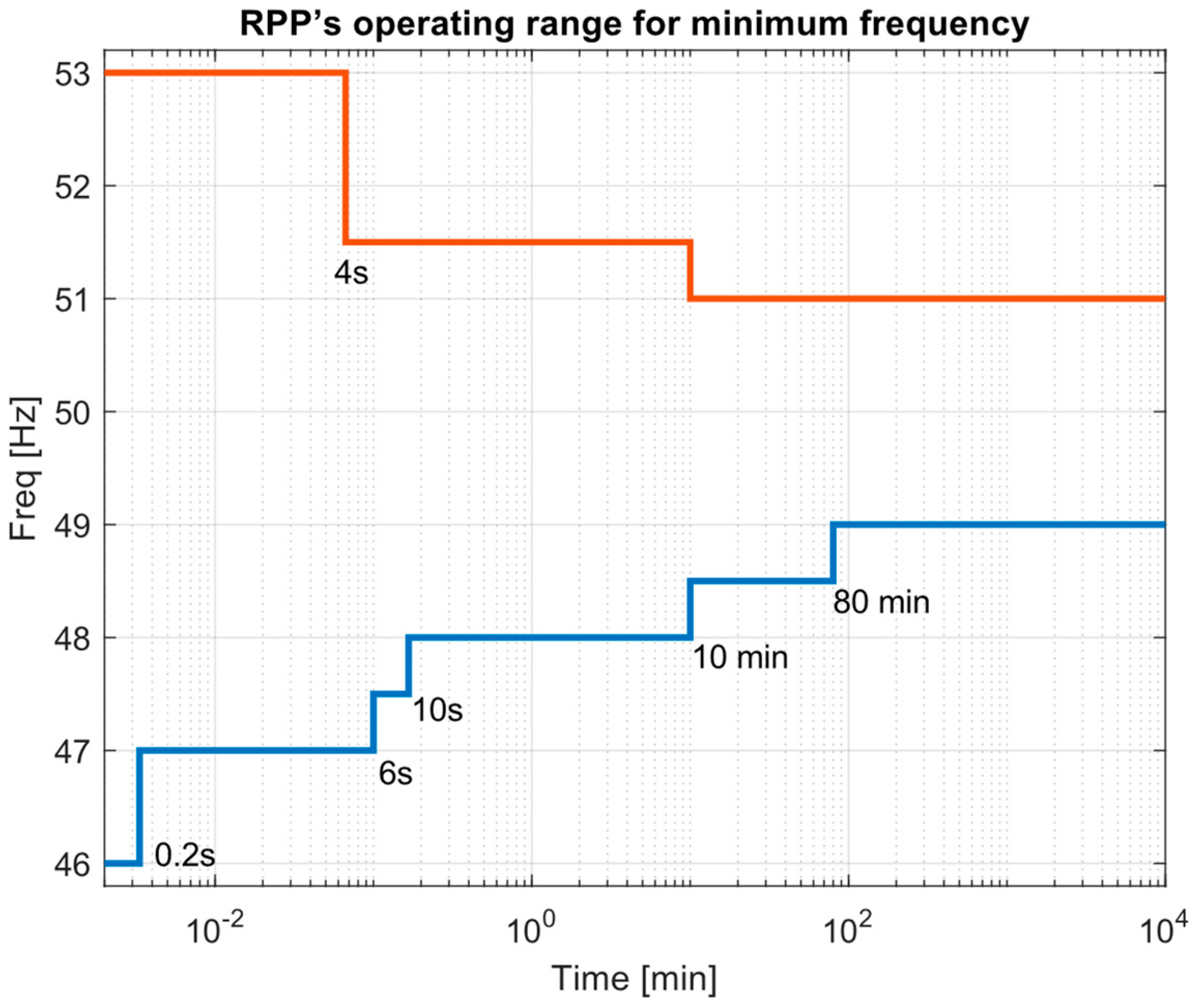
- The RPP may be eliminated if the ENDS frequency exceeds 51.5 Hz for more than 4 s or if it dips below 47.0 Hz for more than 200 milliseconds. The RPP shall continue to be connected to the ENDS even if the system frequency varies up to and including 1.5 Hz per second as long as it continues within the minimal level operational range shown in Figure 1 and Figure 2.
2.1.2. Operating Conditions under Disturbance
- Voltage Response
- B.
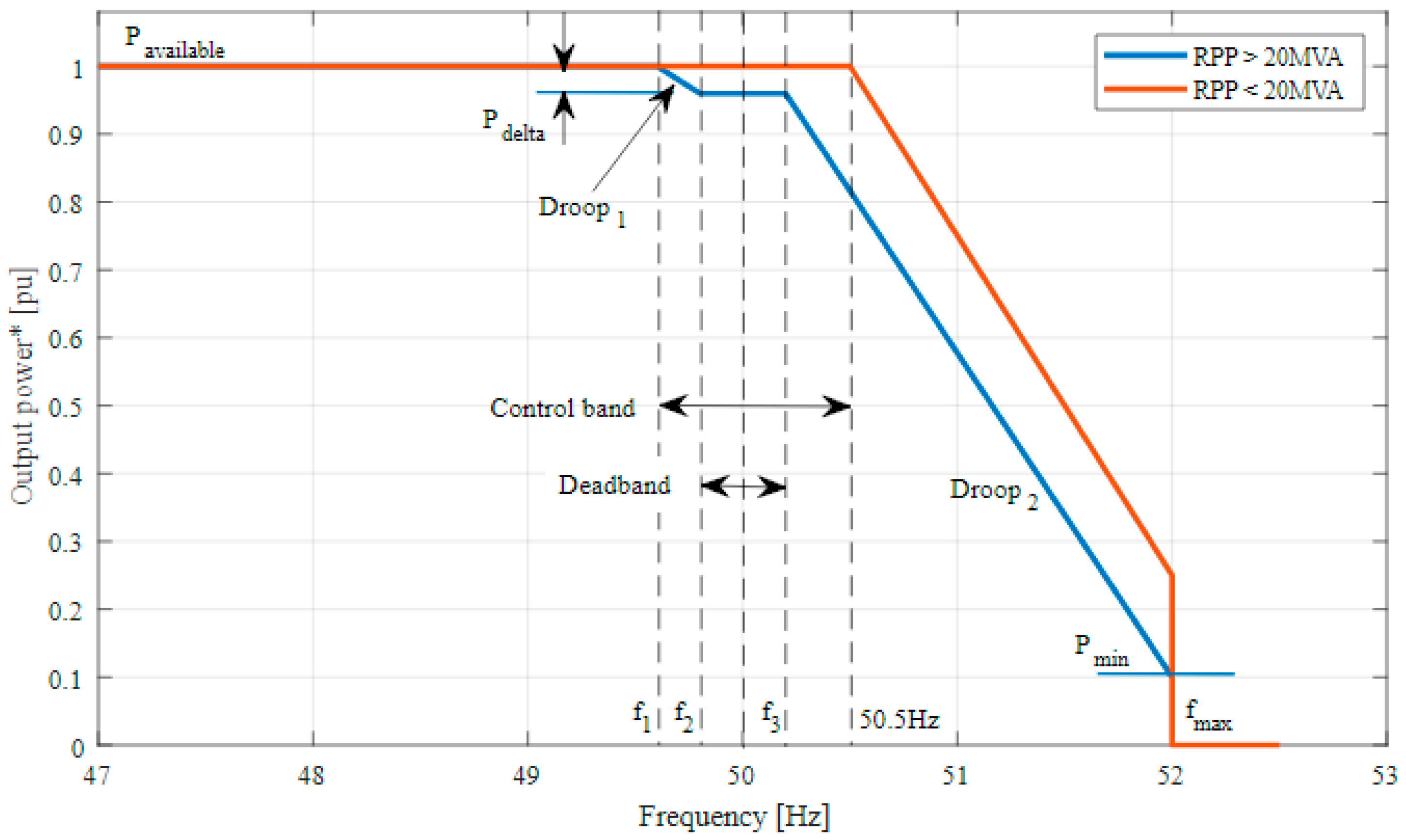
- Frequency Response
- 1.
- Power–Frequency Response Curve for RPP
- 2.
- Power–Frequency Response Curve for RPP of δ category
- C.
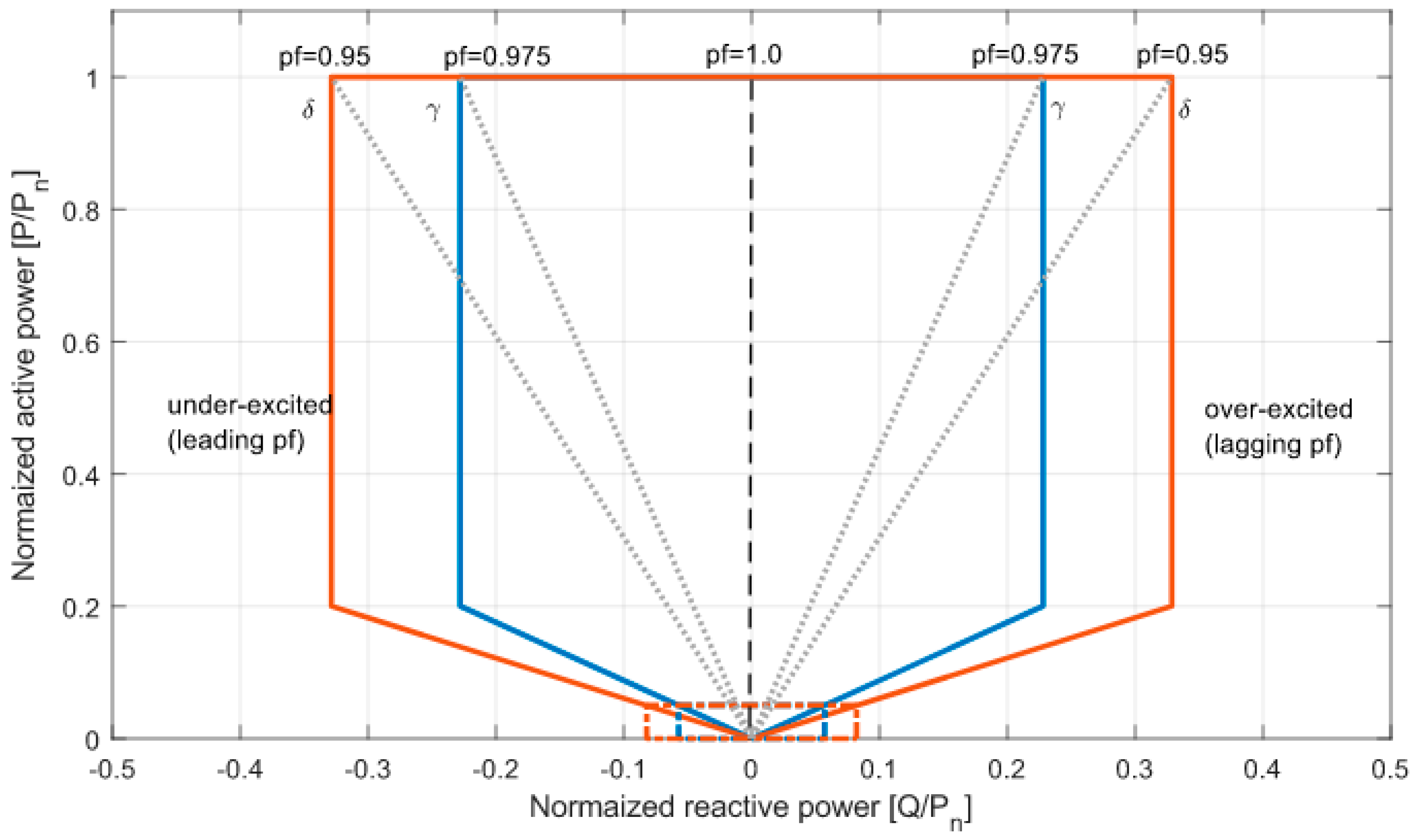
- Reactive Power Capability
- 1.
- RPPs of α category (below 1 MVA)
- 2.
- RPPs of γ category
- 3.
- RPPs of δ category
- D.
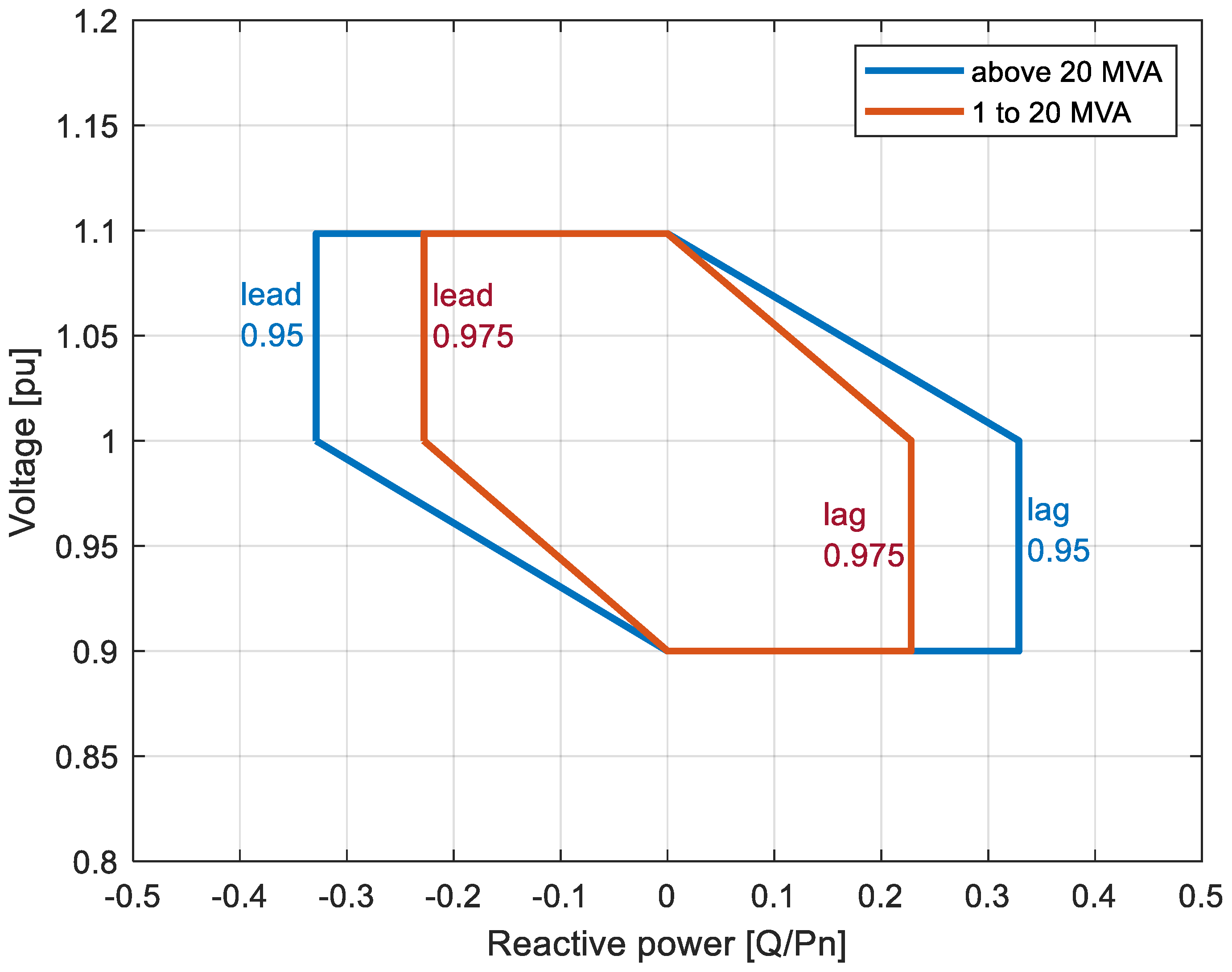
- Reactive Power, Power Factor, and Voltage Control
- The RPP must have both a voltage control function and reactive power control capabilities that allow it to manage the voltage as well as the reactive power it delivers at the POC.
- One of the three functions—voltage, power factor, and reactive power—can only be employed at a time since the management of reactive power and voltage functions is often mutually exclusive.
- The control function and relevant parameter values for the reactive power and voltage control functions, which will be carried out by the RPP, shall be specified by the distribution network system planner in conjunction with the regional control center and/or the system operator. The specified control functions shall be set out in the operating agreement.
- 1.
- Reactive Power Control
- 2.
- Power Factor Control
- 3.
- Voltage Control
- E.
- Power Quality
2.2. Protection and Fault Levels
2.3. Active Power Constraint Functions
2.3.1. Absolute Power Constraint
2.3.2. Delta Production Constraint
2.3.3. Power Gradient Constraint
2.4. Control Function Requirements
2.5. Ramp Rates
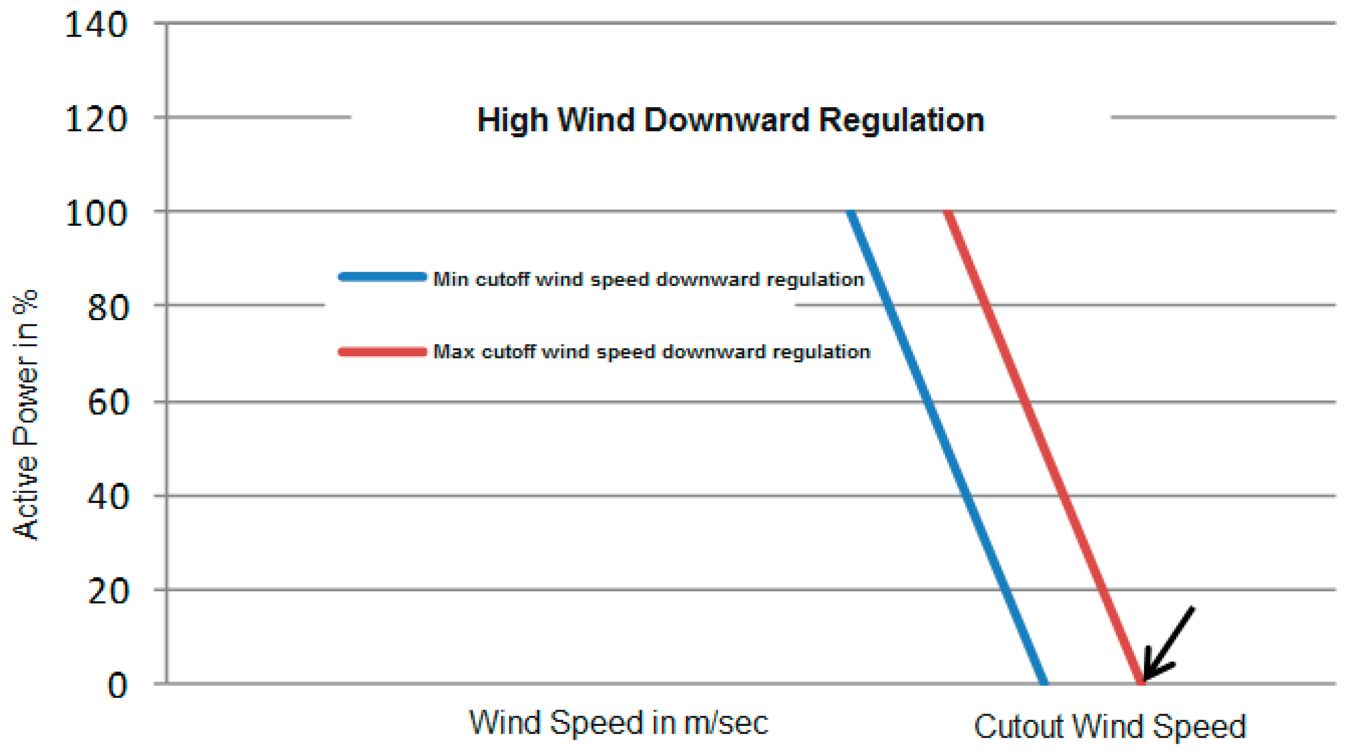
2.6. High Wind Curtailment
2.7. RPP System Reserve Requirement
- (a)
- Within the design margins, maintain at least two separate set amounts of spinning reserve.
- (b)
- Maintain the spinning reserve set level within 2% of the registered capacity with the DNSP, the regional control center, and/or the system operator for at least one hour.
3. Comparative Analysis
3.1. Comparative Analysis of the Grid Codes (Danish versus Ethiopia)
3.2. Comparative Analysis between the Ethiopian Grid Code and IEEE 1547-2003 and IEEE 1547-2018 Standards
4. Summary of the Ethiopian Grid Code
5. Evaluation and Recommendation of the Ethiopian Grid Codes Modifications
- Requirements related to the reactive power compensation are required to be incorporated. Similarly, specifications related to the ancillary services are required to be incorporated.
- A critical issue related to the hosting capacity of the distribution network is required to be incorporated. In the presented Ethiopian grid code draft, information related to the hosting capacity of the distribution network after the incorporation of renewable energy sources is unavailable. Some general rules are required to determine hosting capacity with renewable energy integration. This will depend on the grid transformer/cable capacity such as impedance, short circuit current, etc. Further, both the power and current should be evaluated, and also the harmonics for this purpose.
- A detailed framework related to the procedures and implementation of the information and communication technologies, their standard, and protocols are completely missing from the existing Ethiopian grid code document.
- Low-voltage ride-through (LVRT) capability requirements are mentioned in the grid code document but the requirements related to the High-voltage ride-through (HVRT) capability are not available in the document. Further, Fault ride-through (FRT) capability requirements are also not clearly available in the document. The limits for these capabilities can be determined based on the type and size of the renewable energy sources utilized in the system.
- Detailed framework related to the information transfer is unavailable.
- Intentional islanding criteria and other related information are available in the Ethiopian grid code, but detailed information about the protection system to detect unintentional islanding is not presented. A suitable method (active or passive) for unintentional islanding can be selected based on the requirements of the system.
- There is no information available regarding the DC current components’ presence in the grid. If it is available, how the system will deal with certain issues should also be discussed in the Ethiopian grid code document. DC content of the current injected by the plant into the grid should be below 0.5% of the nominal current of the plant.
- There is no discussion available related to the automatic power factor control.
- Nothing in the Ethiopian GC is mentioned regarding automated synchronization. The paper is also missing information on automated reconnection. When synchronization is involved, the operation is completed within ±5 min of the scheduled synchronization time. The synchronized generation obtained is within a tolerance limit of the reported net capacity error of 2.5%.
- Deployment of smart meters is a critical issue to integrate renewable energy sources at the distribution level, but the existing Ethiopian grid code does not discuss any information related to the implementation of smart meter technology in the existing distribution system. Critical studies related to the status of the system are required for the adequate deployment of the smart meters.
- Energy management system development at the distribution level is also critical for the integration of renewable energy sources at the distribution level, but the present document does not provide any information regarding the development, type, and implantation of such system into the distribution network.
- Incorporation of the controllable loads at the distribution level is also one issue that could be incorporated into the existing Ethiopian grid code documents. Some regulations based on the over/under voltage and frequency controls could be implemented if problems occur.
- Flexibility issues related to the integration of renewable energy sources are also missing in the Ethiopian grid code.
- Discussion about the impact of electric vehicle integration and charging on distribution networks is missing.
6. Pros and Cons of Recommended Ethiopian Grid Code
6.1. Advantages
- The proposed grid code supports the better implementation of smart grid technology in the Ethiopian distribution system.
- The recommended grid code supports the incorporation of various capacity renewable energy sources (recommended in the manuscript) at the distribution level in a more adequate way.
- The proposed grid code adequately operates and controls the renewable energy sources (as their operating ranges are critically discussed under normal and abnormal conditions) integrated at the distribution level.
- The recommended grid code suggests the integration of electric vehicle technology to the distribution level in a better way.
- The recommended grid code suggests the better implementation of ICT technologies in the Ethiopian distribution system
6.2. Limitations
- For the implementation of the proposed recommendations, capital requirement will be the major issue.
- Implementation of advanced controlling techniques such as artificial intelligence techniques is still not discussed in the grid code.
7. Conclusions
Author Contributions
Funding
Institutional Review Board Statement
Informed Consent Statement
Data Availability Statement
Acknowledgments
Conflicts of Interest
References
- Khan, B.; Singh, P. The Current and Future States of Ethiopia’s Energy Sector and Potential for Green Energy: A Comprehensive Study. Int. J. Eng. Res. Afr. 2017, 33, 115–139. [Google Scholar] [CrossRef]
- Ayetor, G.; Mbonigaba, I.; Sunnu, A.; Nyantekyi-Kwakye, B. Impact of replacing ICE bus fleet with electric bus fleet in Africa: A lifetime assessment. Energy 2021, 221, 119852. [Google Scholar] [CrossRef]
- Singh, P.; Khan, B.; Alhelou, H.H.; Mahela, O.P. Impressions of remote area electrification on social and economic indicators. AIMS Energy 2020, 8, 1045–1068. [Google Scholar] [CrossRef]
- Hailu, A.D.; Kumsa, D.K. Ethiopia renewable energy potentials and current state. AIMS Energy 2021, 9, 1–14. [Google Scholar] [CrossRef]
- Nigussie, T.; Bogale, W.; Bekele, F.; Dribssa, E. Feasibility study for power generation using off- grid energy system from micro hydro-PV-diesel generator-battery for rural area of Ethiopia: The case of Melkey Hera village, Western Ethiopia. AIMS Energy 2017, 5, 667–690. [Google Scholar] [CrossRef]
- Sabo, M.L.; Mariun, N.; Hizam, H.; Radzi, M.A.M.; Zakaria, A. Spatial matching of large-scale grid-connected photovoltaic power generation with utility demand in Peninsular Malaysia. Appl. Energy 2017, 191, 663–688. [Google Scholar] [CrossRef]
- Yang, Y.; Enjeti, P.; Blaabjerg, F.; Wang, H. Wide-scale adoption of photovoltaic energy: Grid code modifications are explored in the distribution grid. IEEE Ind. Appl. Mag. 2015, 21, 21–31. [Google Scholar] [CrossRef] [Green Version]
- Rodrigues, E.; Bizuayehu, A.; Catalao, J.P. Analysis of requirements in insular grid codes for large-scale integration of renewable generation. In Proceedings of the 2014 T&D Conference and Exposition, Medellin, Colombia, 10–13 September 2014; IEEE: Piscataway, NJ, USA, 2014; pp. 1–5. [Google Scholar]
- Obi, M.; Bass, R. Trends and challenges of grid-connected photovoltaic systems—A review. Renew. Sustain. Energy Rev. 2016, 58, 1082–1094. [Google Scholar] [CrossRef]
- Mohseni, M.; Islam, S.M. Review of international grid codes for wind power integration: Diversity, technology and a case for global standard. Renew. Sustain. Energy Rev. 2012, 16, 3876–3890. [Google Scholar] [CrossRef]
- Díaz-González, F.; Hau, M.; Sumper, A.; Gomis-Bellmunt, O. Participation of wind power plants in system frequency control: Review of grid code requirements and control methods. Renew. Sustain. Energy Rev. 2014, 34, 551–564. [Google Scholar] [CrossRef]
- Yu, H.; Niu, S.; Shao, Z.; Jian, L. A scalable and reconfigurable hybrid AC/DC microgrid clustering architecture with decentralized control for coordinated operation. Int. J. Electr. Power Energy Syst. 2022, 135, 107476. [Google Scholar] [CrossRef]
- Li, Z.L.; Li, P.; Yuan, Z.P.; Xia, J.; Tian, D. Optimized utilization of distributed renewable energies for island microgrid clusters considering solar-wind correlation. Electr. Power Syst. Res. 2022, 206, 107822. [Google Scholar] [CrossRef]
- Ouammi, A. Model predictive control for optimal energy management of connected cluster of microgrids with net zero energy multi-greenhouses. Energy 2021, 234, 121274. [Google Scholar] [CrossRef]
- Saki, R.; Kianmehr, E.; Rokrok, E.; Doostizadeh, M.; Khezri, R.; Shafie-khah, M. Interactive Multi-level planning for energy management in clustered microgrids considering flexible demands. Int. J. Electr. Power Energy Syst. 2022, 138, 107978. [Google Scholar] [CrossRef]
- Ouammi, A.; Zejli, D. Centralized controller for the optimal operation of a cooperative cluster of connected microgrids powered multi-greenhouses. Sustain. Comput. Inform. Syst. 2022, 33, 100641. [Google Scholar] [CrossRef]
- Indian Electricity Grid Code. Available online: https://powermin.gov.in/en/content/indian-electricity-grid-code (accessed on 21 December 2021).
- Regulations for Grid Connection. Available online: https://en.energinet.dk/Electricity/Rules-and-Regulations/Regulations-for-grid-connection (accessed on 23 December 2021).
- Grid Standards and Codes. Available online: https://www.nrel.gov/grid/standards-codes.html (accessed on 4 January 2022).
- Gunther, E. Harmonic and interharmonic measurement according to IEEE 519 and IEC 61000-4-7. In Proceedings of the 2005/2006 IEEE/PES Transmission and Distribution Conference and Exhibition, Dallas, TX, USA, 21–26 May 2006; pp. 223–225. [Google Scholar]
- Chen, Y.Y.; Chang, G.W.; Lin, C.S. A digital implementation of IEC 61000-4-15 flickermeter. In Proceedings of the 2015 IEEE Power & Energy Society General Meeting, Denver, CO, USA, 26–30 July 2015; pp. 1–5. [Google Scholar]
- Legarreta, A.E.; Figueroa, J.H.; Bortolin, J.A. An IEC 61000-4-30 class a—Power quality monitor: Development and performance analysis. In Proceedings of the 11th International Conference on Electrical Power Quality and Utilisation, Lisbon, Portugal, 17–19 October 2011; pp. 1–6. [Google Scholar]
- IEC 61000-3-2:2018; Electromagnetic Compatibility (EMC)—Part 3-2: Limits—Limits for Harmonic Current Emissions (Equipment Input Current ≤ 16 A Per Phase). IEC: London, UK, 2018. Available online: https://webstore.iec.ch/publication/28164 (accessed on 6 January 2022).
- IEEE Std 519-2014; IEEE Recommended Practice and Requirements for Harmonic Control in Electric Power Systems. (Revision of IEEE Std 519-1992). IEEE: Piscataway, NJ, USA, 2014; pp. 1–29.
- IEEE Std 1547-2018; IEEE Standard for Interconnection and Interoperability of Distributed Energy Resources with Associated Electric Power Systems Interfaces. (Revision of IEEE Std 1547-2003). IEEE: Piscataway, NJ, USA, 2018; pp. 1–138.
- IEC 61850:2022; SER Series, Communication Networks and Systems for Power Utility Automation. IEC: London, UK, 2022. Available online: https://webstore.iec.ch/publication/6028 (accessed on 10 March 2022).


| Parameter | Danish Grid Code | Ethiopian Grid Code | Comments |
|---|---|---|---|
| Voltage Phase Jump | Plant capable of withstanding up to 20-degree transient voltage phase jumps at POC without disconnecting. | The plant must be capable of withstanding abrupt phase jumps at the POC of up to 20 degrees without cutting out or lowering its output. After a phase leap of more than 20 degrees, the plant must restart regular output no later than 5 s after normal operating conditions are achieved at the POC. | Similar to Danish Code, therefore, no further correction is required. |
| Tolerance for frequency and voltage deviations | Continuous generation in the 49.0–51.0 Hz frequency range. Voltage at POC is 230 V. Continuous generation at POC when voltage is within the 85% to 110% range of nominal voltage. Continuous generation under ROCOF up to 2.0 Hz/s. | The generator will continue to operate between 48.75 and 51.25 Hz. The generator should be in operation for 3 s between 48.0 and 52 Hz but will not operate continuously outside of that range. Plant remains connected when the rate of change in frequency (ROCOF) of values up to 1.5 Hz per second Allowable voltage variation less than 1.kV for urban load is varying from ±6% to ±10% Allowable voltage variation for 1 kV and above rural load is ±5%. | Frequency and voltage deviation ranges are so similar to the Danish grid code, hence no further modifications are required. |
| Reduction of active power | Plant is allowed to reduce the active power within the 49-47.5 Hz frequency range by 6% of Pn/Hz—under-frequency | When the system’s frequency surpasses 50.5 Hz, the plant should lower its active power in proportion to the frequency change. Plant shall be tripped to protect the network once the frequency exceeds 51.5 Hz for more than 4 s | The reduction in the active power due to frequency and voltage deviation depends on the power–frequency response curve. |
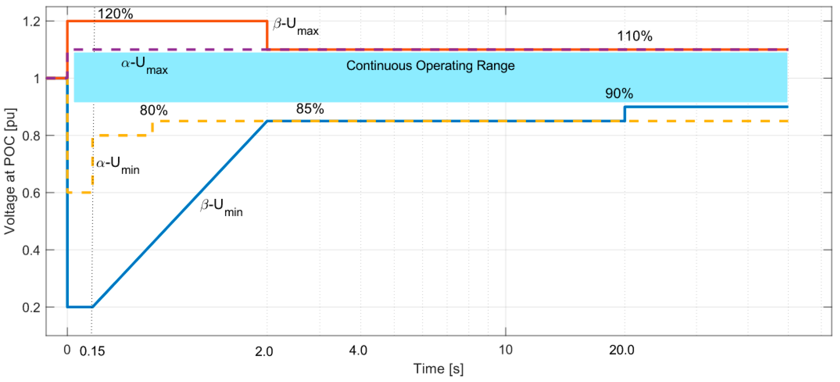
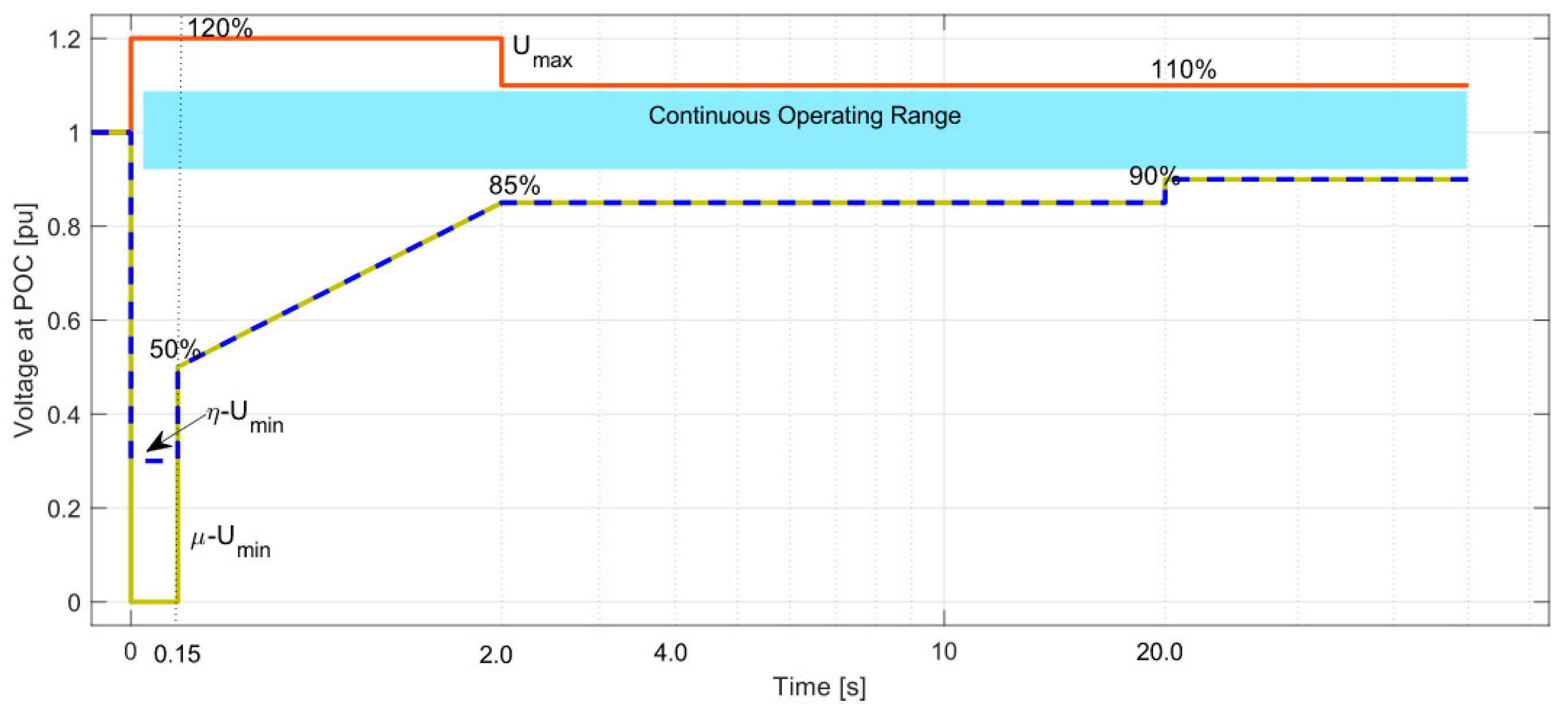
| Voltage drop | Plant must be designed to withstand voltage deviations during normal and abnormal operating conditions. | Except for synchronous generators (size 1–20 MVA) during symmetrical 3-phase failures, the plant withstand voltage must drop to zero for a minimum of 0.150 s without disconnecting. Active power must be maintained during voltage decreases; however, for voltages below 85%, active power must be reduced within the plant’s design parameters in proportion to the voltage drop. | Voltage drops to zero are permitted in the Ethiopian grid code for a minimum of 0.150 s. The same applies to asynchronous power modules in Denmark. |
| Voltage rise | Plant must be designed to withstand voltage deviations during normal and abnormal operating conditions. | Plant (20 MVA and above) must be able to endure voltage peaks of up to 120 percent of the normal voltage for at least 2 s before disconnecting. | The maximum voltage rise allowed in the Ethiopian grid code is up to 120% for short time duration of 2 s. |
| Connection and reconnection | Start-up and reconnection of a plant are only permitted when frequency and voltage are within the 47.5 to 50.2/50.5 Hz and 85% to 110% of nominal voltage for 3 min, respectively. After connection, the maximum active power increase per minute is 20% of nominal power. | For plant, with capacity higher than 1 MVA, capable of operating continuously within voltage range 0.9 to 1.1 p.u. at 66 kV, and 0.9 to 1.08 p.u. at voltage below 66 kV. Plants greater than 1 MVA are only permitted to connect to the distribution grid 3 s after the following conditions are satisfied. (1) The voltage is within the maximum and minimum allowable limits mentioned above (2) The frequency in the distribution grid is between 49.0 and 50.2 Hz. Plant with a capacity of less than 1 MVA may only connect to the distribution grid 60 s after the following requirements have been met: (1) The voltage is in the −15% to +10% range around the normal value. (2) The distribution system’s frequency is between 49.0 and 50.2 Hz. | The requirements for the starting up and reconnection of the power generating plants are more or less similar to the Danish code. It is very fast in the Ethiopian grid code |
| Absolute Power Constraints | The plant must have the ability to regulate its maximum active power. It restricts the active power coming from an RPP to a maximum power limit at POC that is determined by a set point. Control for a new value of the absolute power limit must be completed within five minutes of receiving the parameter change order. | This restriction is utilized at the POC to constrain the plant output to a predetermined power MW limit. If the set point for this limit is to be changed, the plants shall commence change within 2 s (for small hydro it should be within 5 s) and it should be completed within 30 s The precision of the conducted control and the set point should not diverge by more than ±2% of the set point value or ±0.5 percent of the rated power. | These constraints are also similar to the Danish grid code therefore no further modifications are required. |
| Reactive Power Control | The plant has to be able to manage its reactive power. It caps the reactive power produced by a power plant to a maximum limit determined at POC. | Plant should have a reactive power control system. The plant must update its echo analog set point value in reaction to the new value within 2 s and must finish it within 30 s if the reactive power control set point is. More than 2% of the set point value or 0.5% of the maximum reactive power can be used as the tolerance for the accuracy of the control being conducted and the set point. Reactive power set points for the plant must be accurate to at least 1 kVAr. | Based on the reactive power control function curve, reactive power control of the renewable power plants is carried out. |
| Power Factor control | In order to manage reactive power using a fixed Power Factor, RPP must be able to execute Power Factor control. A new Power Factor set point must be controlled within a minute after being established. | At the POC, Power Factor Control adjusts the reactive power appropriately to the active power. The plant must update its echo analog set point value in response to the new value in response to the power factor set point modification within 2 s and reply within 30 s. The precision of the set point and the control operation cannot differ by more than ±0.02. | In proportion to the active power at the POC, reactive power is managed through power factor control. The set point shouldn’t vary by more than ±0.02 points. |
| Power Quality | The power quality requirements outlined in the various IEEE and IEC standards must be met by the plant. | IEC 61000-4-7, Harmonics Calculation Power quality monitoring for flicker: IEC 61000-4-15 Class A IEC 61000-3-2:2018 Voltage and current quality distortion levels released by the facility at the POC IEEE 519-2014 Standard for Interconnecting Distributed Resources with Electric Power Systems Recommended Practice and Requirements for Harmonic Control: IEEE 1547 | The Ethiopian grid code uses many IEC and IEEE standards to specify the types of power quality issues. |
| Transient and Short Duration Voltage Variations | Plant must not cause rapid voltage changes exceeding the limit value d(%) = 4%. | A brief voltage variation occurs when the voltage deviates from the nominal value for a period longer than a half-cycle of the power frequency but not more than one minute. The term “transient voltages” refers to high-frequency overvoltages that typically last less time than short-duration voltage variations. | A detailed description is available related to the transient and short-duration voltage variations. |
| Current and Voltage Unbalance | The current unbalance between the three phases of a plant must not exceed 16 A. Plants above 11 kW must have balanced three-phase connections | In order to achieve average levels of negative sequence voltage that are equal to or less than the set values, the current drawn should be balanced in each phase at each of its connection points. However, at any nominal voltage, the negative sequence voltage averaged over any 1 min period shall not exceed 2 percent in any hour. | Voltage unbalance information is presented based on the nominal voltage value. |
| Protection System | Plant is responsible for ensuring that it is dimensioned and equipped with the necessary protection functions so that: the plant is protected against damage due to faults and incidents in the public electricity supply grid. Relay settings must not prevent specified power-generating plant functions from functioning properly. Provides protection for the public electricity supply system against unintended effects of the power plant and from harm caused by asynchronous connections. The plant is prevented from disconnecting in non-critical circumstances so that it won’t be harmed or turn off when the voltage drops. | To limit the effects of faults on the distribution level and to achieve the appropriate degree of speed, sensitivity, and selectivity in fault clearing, the protection of plants linked to the distribution grid and accompanying equipment must be developed, coordinated, and tested. The protection system for the electrical equipment and facilities on each of their respective sides of the connection point shall be the exclusive responsibility of the generating licensee. The protection system and switching arrangements should be made to separate the plant after the first main breaker, recloser, or sectionalizer opening, and to remain disconnected until the system has been fully restored, if the distribution network user facilities are connected to a feeder with auto-reclosing capabilities. | A detailed description about the protection schemes and their coordination is available in the Ethiopian grid code. |
| Islanding protection | Plant must detect unintentional island operation and must disconnect from the grid if unintentional islanding is detected. | The plant may be purposefully isolated in order to continue serving nearby consumers even when there is an outage. ANSI/IEEE Std. 1547-2003’s Prevention of Unintended Islanding Operation (Loss of Mains) | Detailed information about protection systems to detect unintentional and intentional islandings are not presented. |
| Information Transfer | Plant is equipped with an interface (controller) at the point of communication enabling real-time exchange of signals. Plant must be acted no later than five seconds after the command to this effect has been received. | To effectively share the necessary information, the plant and big user (more than 2 MVA) will select contact people and agree on communication methods. | Procedures, information Flow, and Coordination, related to the information exchange are presented but a detailed framework is unavailable. |
| Parameters | IEEE 1547-2003 [25] | IEEE 1547-2018 [25] | Ethiopian Grid Code | Comments |
|---|---|---|---|---|
| Scope | Applied to DERs having an overall rating of no more than 10 MVA | Applied to DERs with a combined rating of at least 10 MVA | Applied to 20 MVA or higher | Higher capacity RPPs are incorporated in the Ethiopian grid code |
| Voltage Regulation | Regulation of the voltage at DER’s Point of Common Coupling was forbidden (PCC) | DERs may regulate voltage to a limited extent. | Maintained at the values stated in the Performance Standards Code for voltage regulation | According to the aforementioned criteria, the Ethiopian grid code permits voltage control. |
| Faults and open phases | DERs stop energizing the region There is no information on the open stages. | DERs turn off the Area’s energy The PCC or DER terminals must have an open phase for DER to function. | A fault might cause the generator plant’s link to the distribution network to be severed. | In Ethiopia’s grid code, open phases are not discussed at all. |
| Power Quality | Setting basic limits for power quality issues | A new part of the IEEE 1547-2003 standard is added that addresses the concerns listed below: 1. Inter-harmonic limits 2. DER contribution in Flicker 3. Rapid voltage change 4. Transient overvoltage | IEC 61000-4-7, Harmonics Calculation IEC 61000-4-15 Class A flicker Monitoring power quality: IEC 61000-4-30 IEC 61000-3-2:2018 Voltage and current quality distortion levels released by the facility at the POC IEEE 519-2014 Standard for Interconnecting Distributed Resources with Electric Power Systems Recommended Practice and Requirements for Harmonic Control: IEEE 1547 | In Ethiopian GC, many IEC and IEEE Standards are mentioned for handling Power quality concerns. |
| Islanding | Solely the prevention of unintended islanding was discussed | Discussions are made of both unintentional and purposeful islanding. | Discussions are made of both unintentional and purposeful islanding. | There is no detailed information provided on the protection mechanism to identify accidental and deliberate islandings. |
| Communications | There is no standard for information sharing. | emphasis on the need for communications and compatibility with the standard being considered | Communication networks and management systems are explored in relation to the IEC 61850 standard. | Details of the information exchange’s procedures, information flow, and coordination are supplied; however, the Ethiopian GC lacks a detailed framework. |
Publisher’s Note: MDPI stays neutral with regard to jurisdictional claims in published maps and institutional affiliations. |
© 2022 by the authors. Licensee MDPI, Basel, Switzerland. This article is an open access article distributed under the terms and conditions of the Creative Commons Attribution (CC BY) license (https://creativecommons.org/licenses/by/4.0/).
Share and Cite
Khan, B.; Guerrero, J.M.; Chaudhary, S.; Vasquez, J.C.; Frederiksen, K.H.B.; Wu, Y. A Review of Grid Code Requirements for the Integration of Renewable Energy Sources in Ethiopia. Energies 2022, 15, 5197. https://0-doi-org.brum.beds.ac.uk/10.3390/en15145197
Khan B, Guerrero JM, Chaudhary S, Vasquez JC, Frederiksen KHB, Wu Y. A Review of Grid Code Requirements for the Integration of Renewable Energy Sources in Ethiopia. Energies. 2022; 15(14):5197. https://0-doi-org.brum.beds.ac.uk/10.3390/en15145197
Chicago/Turabian StyleKhan, Baseem, Josep M. Guerrero, Sanjay Chaudhary, Juan C. Vasquez, Kenn H. B. Frederiksen, and Ying Wu. 2022. "A Review of Grid Code Requirements for the Integration of Renewable Energy Sources in Ethiopia" Energies 15, no. 14: 5197. https://0-doi-org.brum.beds.ac.uk/10.3390/en15145197