Design of a Hybrid Electric Vehicle Powertrain for Performance Optimization Considering Various Powertrain Components and Configurations

 ,
, 
 ,
, 
Abstract
:1. Introduction
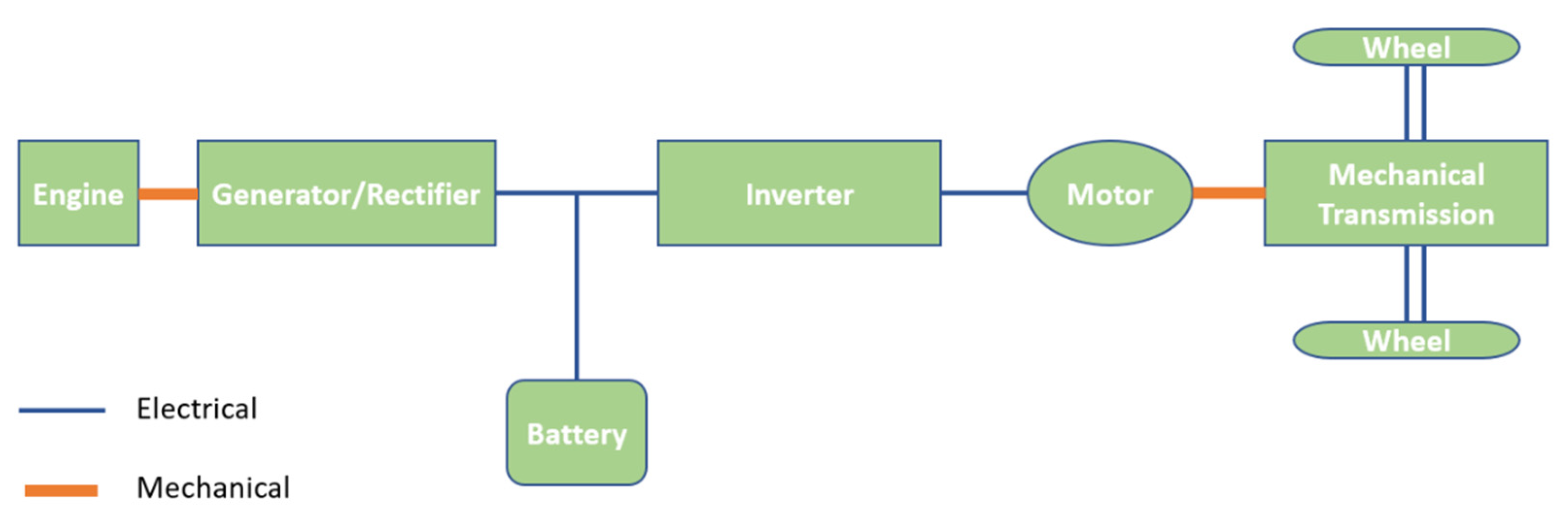
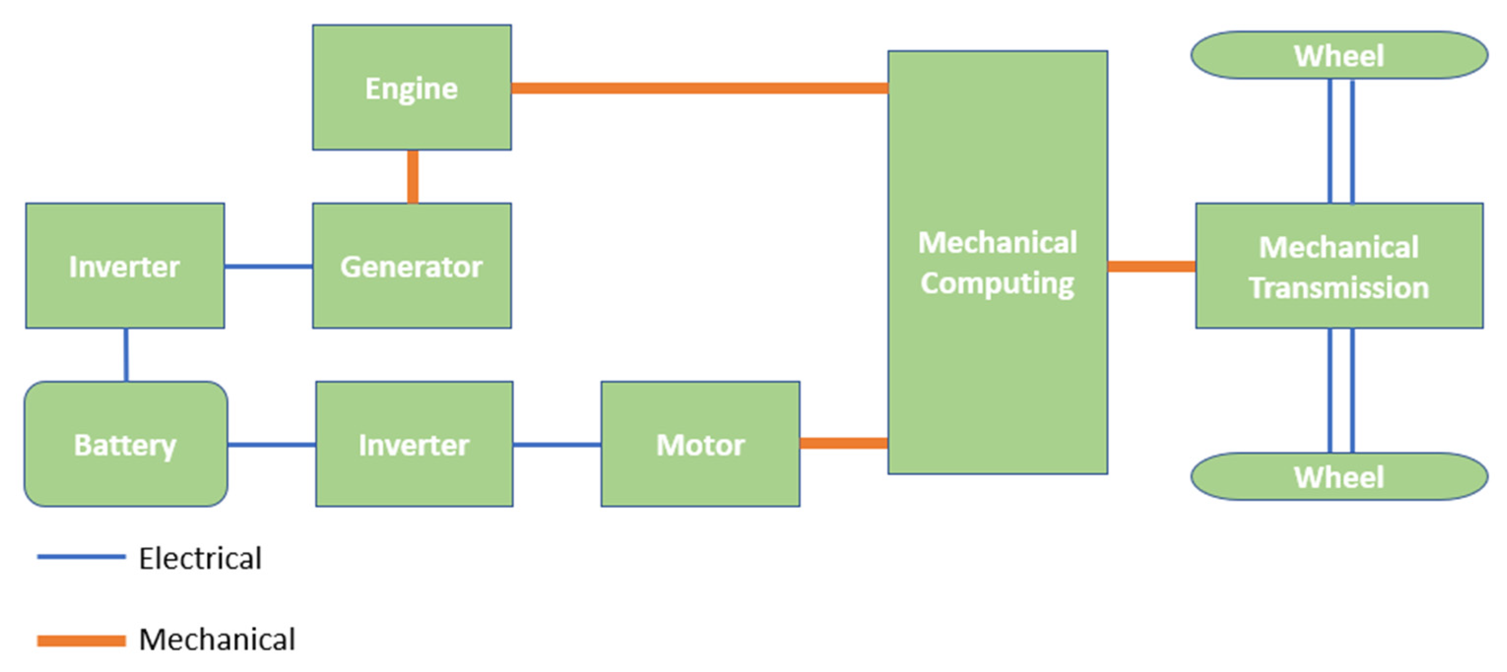
2. Hybrid Powertrain Configurations
3. Powertrain Design Requirements and Constraints
3.1. Vehicle Performance Metrics
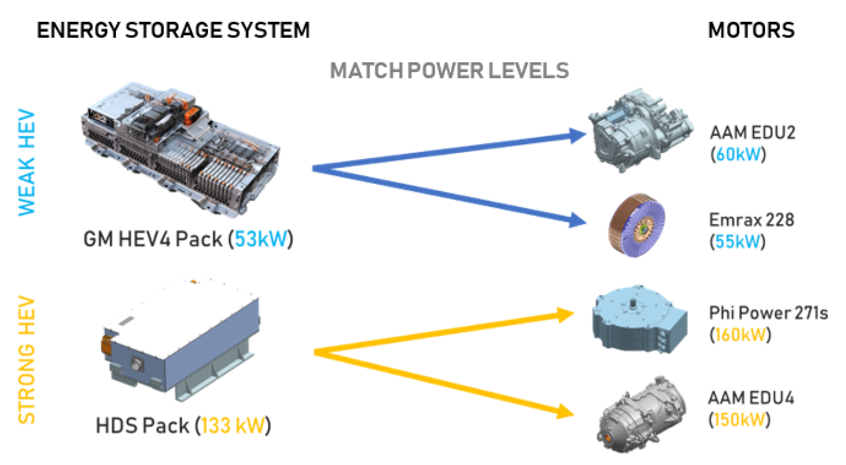
3.2. Available Options for Powertrain Configurations and Components
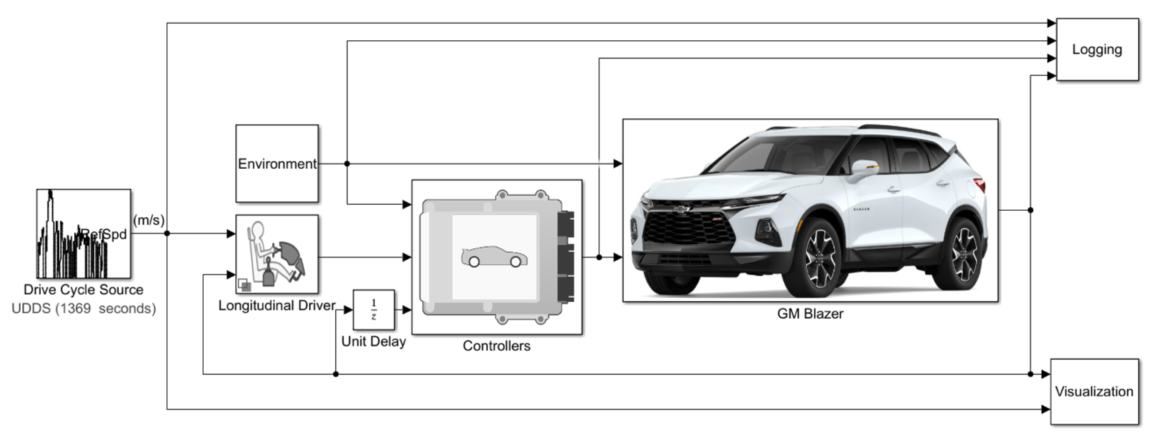
4. Powertrain Modeling in MATLAB/Simulink
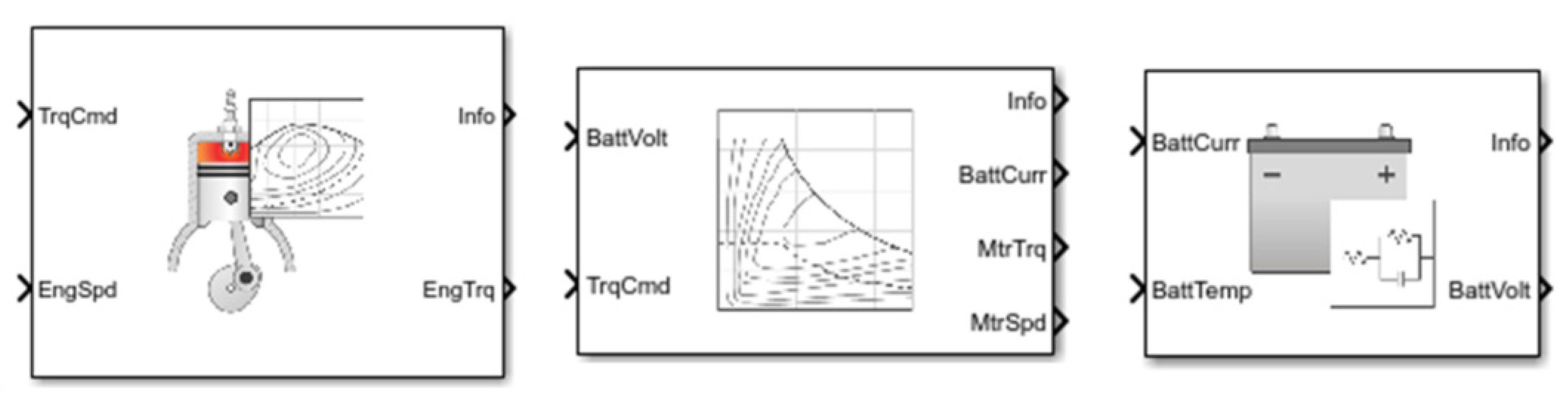
4.1. Powertrain Components Modeling
4.2. Energy Consumption Modeling
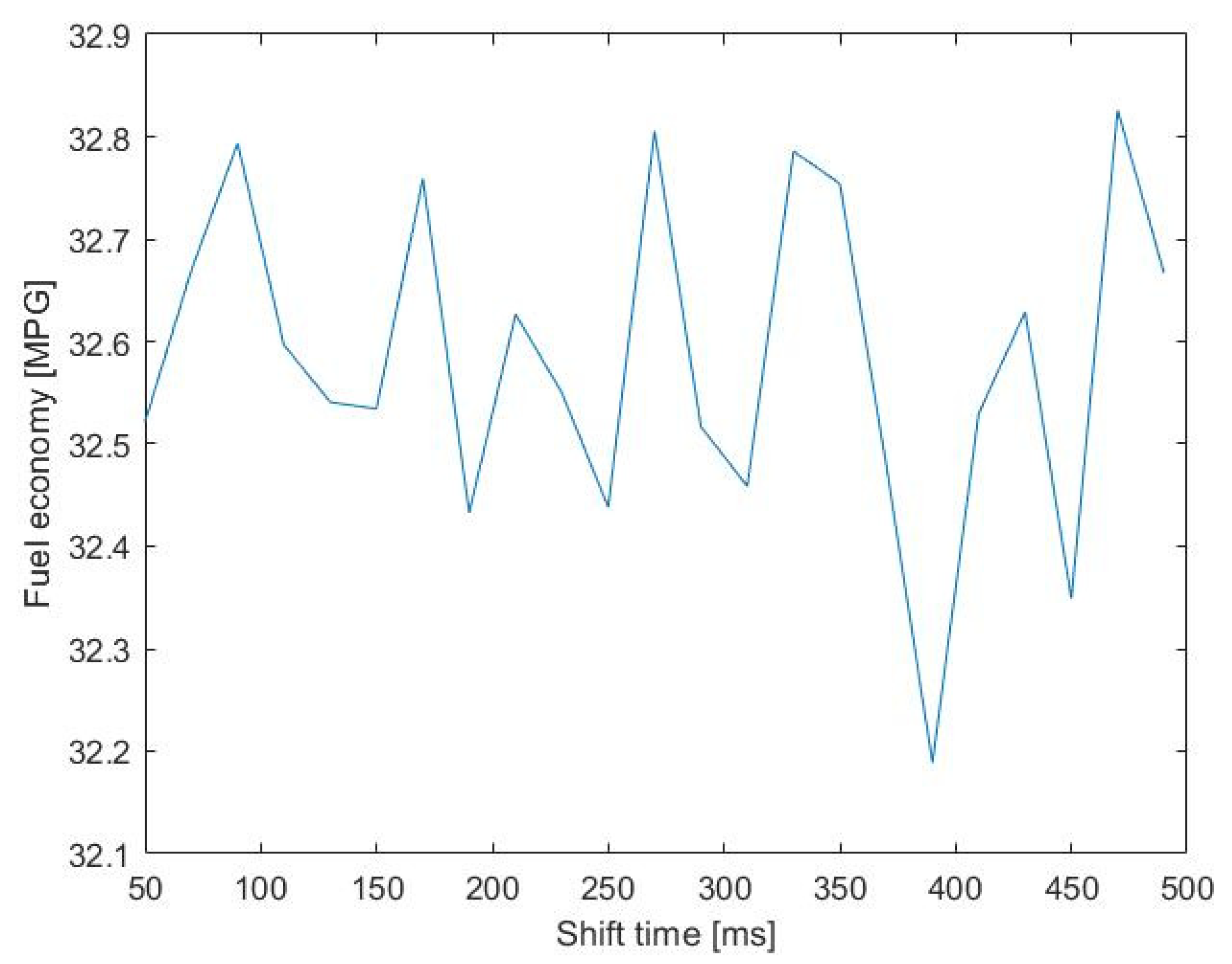
5. Powertrain Simulation Results in MATLAB/Simulink
6. Conclusions
Author Contributions
Funding
Acknowledgments
Conflicts of Interest
References
- Aldhafeeri, T.; Tran, M.-K.; Vrolyk, R.; Pope, M.; Fowler, M. A Review of Methane Gas Detection Sensors: Recent Developments and Future Perspectives. Inventions 2020, 5, 28. [Google Scholar] [CrossRef]
- Shamsi, H.; Tran, M.-K.; Akbarpour, S.; Maroufmashat, A.; Fowler, M. Macro-Level Optimization of Hydrogen Infrastructure and Supply Chain for Zero-emission Vehicles on a Canadian Corridor. J. Clean. Prod. 2020, 125163. [Google Scholar] [CrossRef]
- Taefi, T.T.; Kreutzfeldt, J.; Held, T.; Fink, A. Supporting the adoption of electric vehicles in urban road freight transport—A multi-criteria analysis of policy measures in Germany. Transp. Res. Part A Policy Pract. 2016, 91, 61–79. [Google Scholar] [CrossRef]
- Fathabadi, H. Utilization of electric vehicles and renewable energy sources used as distributed generators for improving characteristics of electric power distribution systems. Energy 2015, 90, 1100–1110. [Google Scholar] [CrossRef]
- Mevawalla, A.; Panchal, S.; Tran, M.-K.; Fowler, M.; Fraser, R. Mathematical Heat Transfer Modeling and Experimental Validation of Lithium-Ion Battery Considering: Tab and Surface Temperature, Separator, Electrolyte Resistance, Anode-Cathode Irreversible and Reversible Heat. Batteries 2020, 6, 61. [Google Scholar] [CrossRef]
- Panchal, S.; Gudlanarva, K.; Tran, M.-K.; Fraser, R.; Fowler, M. High Reynold’s Number Turbulent Model for Micro-Channel Cold Plate Using Reverse Engineering Approach for Water-Cooled Battery in Electric Vehicles. Energies 2020, 13, 1638. [Google Scholar] [CrossRef] [Green Version]
- Garcia, R.; Gregory, J.; Freire, F. Dynamic fleet-based life-cycle greenhouse gas assessment of the introduction of electric vehicles in the Portuguese light-duty fleet. Int. J. Life Cycle Assess 2015, 20, 1287–1299. [Google Scholar] [CrossRef] [Green Version]
- Reuters, Exclusive: VW, China Spearhead $300 billion Global Drive to Electrify Cars. Available online: https://www.reuters.com/article/us-autoshow-detroit-electric-exclusive-idUSKCN1P40G6 (accessed on 23 October 2020).
- Tran, M.-K.; Fowler, M. A Review of Lithium-Ion Battery Fault Diagnostic Algorithms: Current Progress and Future Challenges. Algorithms 2020, 13, 62. [Google Scholar] [CrossRef] [Green Version]
- Hajimiragha, A.; Canizares, C.A.; Fowler, M.W.; Elkamel, A. Optimal Transition to Plug-In Hybrid Electric Vehicles in Ontario, Canada, Considering the Electricity-Grid Limitations. IEEE Trans. Ind. Electron. 2010, 57, 690–701. [Google Scholar] [CrossRef]
- Bloomberg, “Electric Cars May Be Cheaper Than Gas Guzzlers in Seven Years”. Available online: https://news.bloomberglaw.com/environment-and-energy/electric-cars-may-be-cheaper-than-gas-guzzlers-in-seven-years (accessed on 23 October 2020).
- Bonges, H.A.; Lusk, A.C. Addressing electric vehicle (EV) sales and range anxiety through parking layout, policy and regulation. Transp. Res. Part A Policy Pract. 2016, 83, 63–73. [Google Scholar] [CrossRef] [Green Version]
- Sabri, M.F.M.; Danapalasingam, K.A.; Rahmat, M.F. A review on hybrid electric vehicles architecture and energy management strategies. Renew. Sustain. Energy Rev. 2016, 53, 1433–1442. [Google Scholar] [CrossRef]
- Wu, G.; Zhang, X.; Dong, Z. Powertrain architectures of electrified vehicles: Review, classification and comparison. J. Frankl. Inst. 2015, 352, 425–448. [Google Scholar] [CrossRef]
- Tran, M.-K.; Sherman, S.; Samadani, E.; Vrolyk, R.; Wong, D.; Lowery, M.; Fowler, M. Environmental and Economic Benefits of a Battery Electric Vehicle Powertrain with a Zinc–Air Range Extender in the Transition to Electric Vehicles. Vehicles 2020, 2, 398–412. [Google Scholar] [CrossRef]
- Benajes, J.; García, A.; Monsalve-Serrano, J.; Martínez-Boggio, S. Optimization of the parallel and mild hybrid vehicle platforms operating under conventional and advanced combustion modes. Energy Convers. Manag. 2019, 190, 73–90. [Google Scholar] [CrossRef]
- Di Cairano, S.; Bernardini, D.; Bemporad, A.; Kolmanovsky, I.V. Stochastic MPC with Learning for Driver-Predictive Vehicle Control and its Application to HEV Energy Management. IEEE Trans. Control Syst. Technol. 2014, 22, 1018–1031. [Google Scholar] [CrossRef]
- Cheng, H.; Wang, L.; Xu, L.; Ge, X.; Yang, S. An Integrated Electrified Powertrain Topology With SRG and SRM for Plug-In Hybrid Electrical Vehicle. IEEE Trans. Ind. Electron. 2020, 67, 8231–8241. [Google Scholar] [CrossRef]
- Hawkins, T.R.; Gausen, O.M.; Strømman, A.H. Environmental impacts of hybrid and electric vehicles—A review. Int. J. Life Cycle Assess 2012, 17, 997–1014. [Google Scholar] [CrossRef]
- Dagci, O.H.; Peng, H.; Grizzle, J.W. Hybrid Electric Powertrain Design Methodology With Planetary Gear Sets for Performance and Fuel Economy. IEEE Access 2018, 6, 9585–9602. [Google Scholar] [CrossRef]
- Kabalan, B.; Vinot, E.; Yuan, C.; Trigui, R.; Dumand, C.; Hajji, T.E. Efficiency Improvement of a Series-Parallel Hybrid Electric Powertrain by Topology Modification. IEEE Trans. Veh. Technol. 2019, 68, 11523–11531. [Google Scholar] [CrossRef]
- Vora, A.P.; Jin, X.; Hoshing, V.; Saha, T.; Shaver, G.; Varigonda, S.; Wasynczuk, O.; Tyner, W.E. Design-space exploration of series plug-in hybrid electric vehicles for medium-duty truck applications in a total cost-of-ownership framework. Undefined 2017, 202, 662–672. [Google Scholar]
- Lei, F.; Bai, Y.; Zhu, W.; Liu, J. A novel approach for electric powertrain optimization considering vehicle power performance, energy consumption and ride comfort. Energy 2019, 167, 1040–1050. [Google Scholar] [CrossRef]
- Zhou, X.; Qin, D.; Hu, J. Multi-objective optimization design and performance evaluation for plug-in hybrid electric vehicle powertrains. Appl. Energy 2017, 208, 1608–1625. [Google Scholar] [CrossRef]
- EcoCAR Mobility Challenge. Available online: https://avtcseries.org/ecocar-mobility-challenge/ (accessed on 8 September 2018).
- Mi, C.; Masrur, M. Hybrid Electric Vehicles: Principles and Applications with Practical Perspectives, 2nd ed.; Wiley: West Sussex, UK, 2017. [Google Scholar]
- MathWorks. Mapped SI Engine. Available online: https://www.mathworks.com/help/autoblks/ref/mappedsiengine.html (accessed on 2 July 2019).
- MathWorks. Mapped Motor. Available online: https://www.mathworks.com/help/autoblks/ref/mappedmotor.html (accessed on 2 July 2019).
- MathWorks. Equivalent Circuit Battery. Available online: https://www.mathworks.com/help/autoblks/ref/equivalentcircuitbattery.html (accessed on 2 July 2019).
- Tran, M.-K.; Fowler, M. Sensor Fault Detection and Isolation for Degrading Lithium-Ion Batteries in Electric Vehicles Using Parameter Estimation with Recursive Least Squares. Batteries 2020, 6, 1. [Google Scholar] [CrossRef] [Green Version]
- Tran, M.-K.; Mevawala, A.; Panchal, S.; Raahemifar, K.; Fowler, M.; Fraser, R. Effect of integrating the hysteresis component to the equivalent circuit model of Lithium-ion battery for dynamic and non-dynamic applications. J. Energy Storage 2020, 32, 101785. [Google Scholar] [CrossRef]
- Zhang, H.; Wang, J. Adaptive Sliding-Mode Observer Design for a Selective Catalytic Reduction System of Ground-Vehicle Diesel Engines. IEEE/ASME Trans. Mechatron. 2016, 21, 2027–2038. [Google Scholar] [CrossRef]
- Zhang, H.; Wang, J. Active Steering Actuator Fault Detection for An Automatically-steered Electric Ground Vehicle. IEEE Trans. Veh. Technol. 2016, 66, 3685–3702. [Google Scholar] [CrossRef]
- Musardo, C.; Rizzoni, G.; Guezennec, Y.; Staccia, B. A-ECMS: An Adaptive Algorithm for Hybrid Electric Vehicle Energy Management. Eur. J. Control 2005, 11, 509–524. [Google Scholar] [CrossRef]
- Asadi, B.; Vahidi, A. Predictive Cruise Control: Utilizing Upcoming Traffic Signal Information for Improving Fuel Economy and Reducing Trip Time. IEEE Trans. Control Syst. Technol. 2011, 19, 707–714. [Google Scholar] [CrossRef]


| Criteria | Units | Competition Targets |
|---|---|---|
| Acceleration 0–60 mph | s | ≤7 |
| Acceleration 50–70 mph | s | ≤6.5 |
| Braking 60–0 mph | ft | ≤138.4 |
| Total range | mi | ≥250 |
| Combined fuel economy | mpg | ≥33.5 |
| Total emissions | g/mi | ≤373 |
| Code | Displacement | Intake System |
|---|---|---|
| LYX | 1.5 L | Turbocharged |
| LCV | 2.5 L | Naturally Aspirated |
| Battery Pack | Peak Charge Power | Regenerative Braking Capability (Deceleration Rate of 3 m/s2) |
|---|---|---|
| GM HEV4 | 65 kW | 45 km/h |
| HDS | 133 kW | 93 km/h |
| Configuration | P0 | P4 | P4 | P4 | P4 |
|---|---|---|---|---|---|
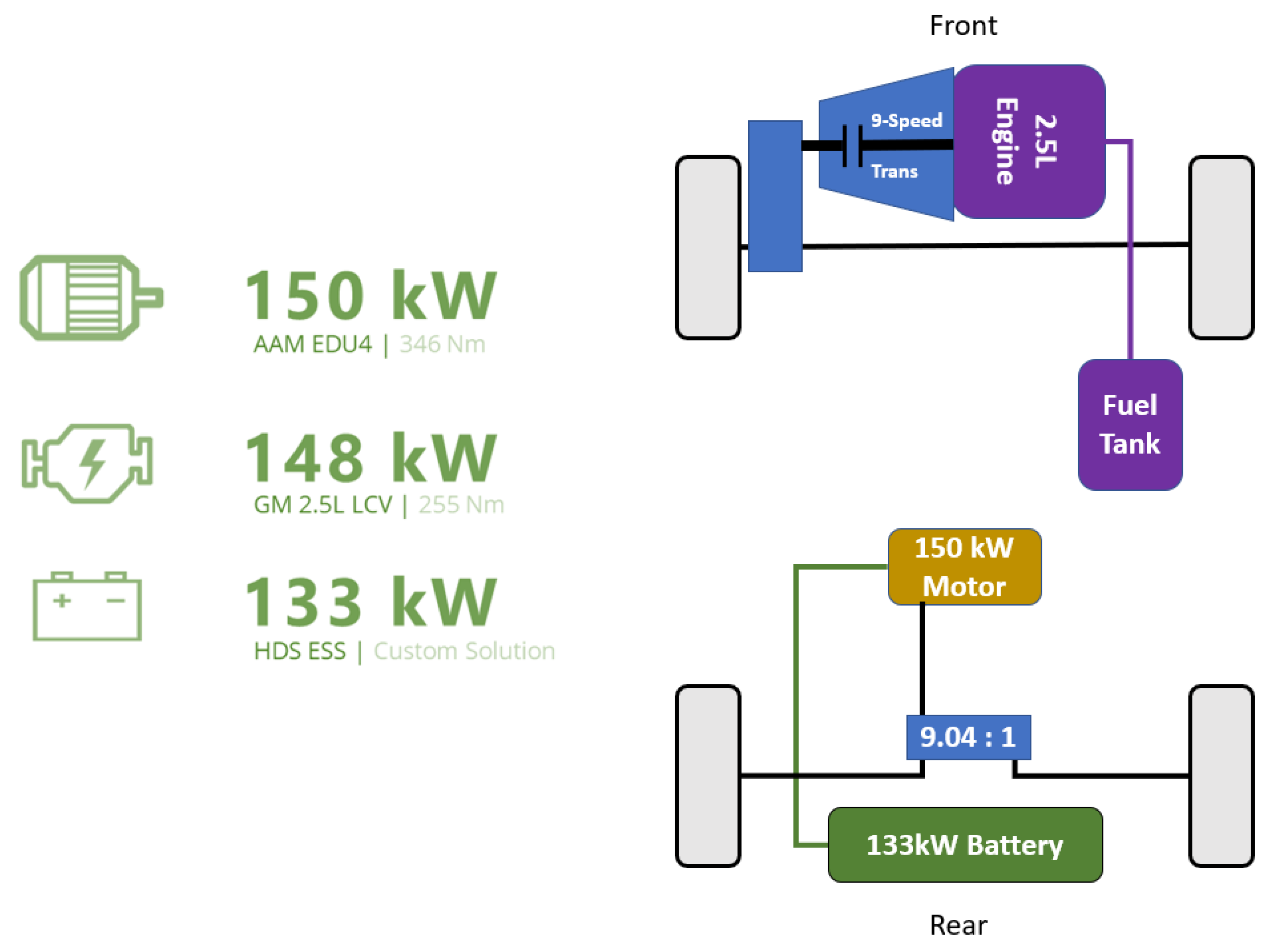
| Engine | GM LYX 1.5 L | GM LCV 2.5 L | GM LCV 2.5 L | GM LCV 2.5 L | GM LCV 2.5 L |
| Motor | Phi Power 271 s | AAM EDU2 | Emrax 228 | Phi Power 271 s | AAM EDU4 |
| Battery | HDS | GM HEV4 | GM HEV4 | HDS | HDS |
| Acceleration 0–60 mph (s) | 4.85 | 5.77 | 6.13 | 4.95 | 4.78 |
| Acceleration 50–70 mph (s) | 3.97 | 4.51 | 5.05 | 4.01 | 4.15 |
| Braking 60–0 mph (ft) | 140.4 | 139.9 | 139.5 | 133.2 | 135.5 |
| Total range (miles) | 313.4 | 310.9 | 307.9 | 309.2 | 308.8 |
| Fuel economy (mpg) | 34.2 | 34.1 | 33.9 | 32.6 | 33.8 |
| Emissions (g/mile) | 159.6 | 17.1 | 15.2 | 87.4 | 43.7 |
| Criteria | Units | Competition Targets | Simulated Performance |
|---|---|---|---|
| Acceleration 0–60 mph | s | ≤7 | 4.78 |
| Acceleration 50–70 mph | s | ≤6.5 | 4.15 |
| Braking 60–0 mph | ft | ≤138.4 | 135.5 |
| Total range | mi | ≥250 | 308.8 |
| Combined fuel economy | mpg | ≥33.5 | 33.8 |
| Total emissions | g/mi | ≤373 | 43.7 |
Publisher’s Note: MDPI stays neutral with regard to jurisdictional claims in published maps and institutional affiliations. |
© 2020 by the authors. Licensee MDPI, Basel, Switzerland. This article is an open access article distributed under the terms and conditions of the Creative Commons Attribution (CC BY) license (http://creativecommons.org/licenses/by/4.0/).
Share and Cite
Tran, M.-K.; Akinsanya, M.; Panchal, S.; Fraser, R.; Fowler, M. Design of a Hybrid Electric Vehicle Powertrain for Performance Optimization Considering Various Powertrain Components and Configurations. Vehicles 2021, 3, 20-32. https://0-doi-org.brum.beds.ac.uk/10.3390/vehicles3010002
Tran M-K, Akinsanya M, Panchal S, Fraser R, Fowler M. Design of a Hybrid Electric Vehicle Powertrain for Performance Optimization Considering Various Powertrain Components and Configurations. Vehicles. 2021; 3(1):20-32. https://0-doi-org.brum.beds.ac.uk/10.3390/vehicles3010002
Chicago/Turabian StyleTran, Manh-Kien, Mobaderin Akinsanya, Satyam Panchal, Roydon Fraser, and Michael Fowler. 2021. "Design of a Hybrid Electric Vehicle Powertrain for Performance Optimization Considering Various Powertrain Components and Configurations" Vehicles 3, no. 1: 20-32. https://0-doi-org.brum.beds.ac.uk/10.3390/vehicles3010002